EP4484723A1 - Turbosoufflante suralimentée à cycle de récupération - Google Patents
Turbosoufflante suralimentée à cycle de récupération Download PDFInfo
- Publication number
- EP4484723A1 EP4484723A1 EP24184994.2A EP24184994A EP4484723A1 EP 4484723 A1 EP4484723 A1 EP 4484723A1 EP 24184994 A EP24184994 A EP 24184994A EP 4484723 A1 EP4484723 A1 EP 4484723A1
- Authority
- EP
- European Patent Office
- Prior art keywords
- turbofan
- fan
- turbine
- airfoils
- swirl
- Prior art date
- Legal status (The legal status is an assumption and is not a legal conclusion. Google has not performed a legal analysis and makes no representation as to the accuracy of the status listed.)
- Pending
Links
Images


Classifications
-
- F—MECHANICAL ENGINEERING; LIGHTING; HEATING; WEAPONS; BLASTING
- F02—COMBUSTION ENGINES; HOT-GAS OR COMBUSTION-PRODUCT ENGINE PLANTS
- F02C—GAS-TURBINE PLANTS; AIR INTAKES FOR JET-PROPULSION PLANTS; CONTROLLING FUEL SUPPLY IN AIR-BREATHING JET-PROPULSION PLANTS
- F02C3/00—Gas-turbine plants characterised by the use of combustion products as the working fluid
- F02C3/04—Gas-turbine plants characterised by the use of combustion products as the working fluid having a turbine driving a compressor
- F02C3/045—Gas-turbine plants characterised by the use of combustion products as the working fluid having a turbine driving a compressor having compressor and turbine passages in a single rotor-module
- F02C3/05—Gas-turbine plants characterised by the use of combustion products as the working fluid having a turbine driving a compressor having compressor and turbine passages in a single rotor-module the compressor and the turbine being of the radial flow type
-
- F—MECHANICAL ENGINEERING; LIGHTING; HEATING; WEAPONS; BLASTING
- F02—COMBUSTION ENGINES; HOT-GAS OR COMBUSTION-PRODUCT ENGINE PLANTS
- F02C—GAS-TURBINE PLANTS; AIR INTAKES FOR JET-PROPULSION PLANTS; CONTROLLING FUEL SUPPLY IN AIR-BREATHING JET-PROPULSION PLANTS
- F02C3/00—Gas-turbine plants characterised by the use of combustion products as the working fluid
- F02C3/04—Gas-turbine plants characterised by the use of combustion products as the working fluid having a turbine driving a compressor
- F02C3/10—Gas-turbine plants characterised by the use of combustion products as the working fluid having a turbine driving a compressor with another turbine driving an output shaft but not driving the compressor
- F02C3/103—Gas-turbine plants characterised by the use of combustion products as the working fluid having a turbine driving a compressor with another turbine driving an output shaft but not driving the compressor the compressor being of the centrifugal type
-
- F—MECHANICAL ENGINEERING; LIGHTING; HEATING; WEAPONS; BLASTING
- F02—COMBUSTION ENGINES; HOT-GAS OR COMBUSTION-PRODUCT ENGINE PLANTS
- F02C—GAS-TURBINE PLANTS; AIR INTAKES FOR JET-PROPULSION PLANTS; CONTROLLING FUEL SUPPLY IN AIR-BREATHING JET-PROPULSION PLANTS
- F02C3/00—Gas-turbine plants characterised by the use of combustion products as the working fluid
- F02C3/14—Gas-turbine plants characterised by the use of combustion products as the working fluid characterised by the arrangement of the combustion chamber in the plant
- F02C3/145—Gas-turbine plants characterised by the use of combustion products as the working fluid characterised by the arrangement of the combustion chamber in the plant the combustion chamber being in the reverse flow-type
-
- F—MECHANICAL ENGINEERING; LIGHTING; HEATING; WEAPONS; BLASTING
- F02—COMBUSTION ENGINES; HOT-GAS OR COMBUSTION-PRODUCT ENGINE PLANTS
- F02C—GAS-TURBINE PLANTS; AIR INTAKES FOR JET-PROPULSION PLANTS; CONTROLLING FUEL SUPPLY IN AIR-BREATHING JET-PROPULSION PLANTS
- F02C7/00—Features, components parts, details or accessories, not provided for in, or of interest apart form groups F02C1/00 - F02C6/00; Air intakes for jet-propulsion plants
- F02C7/08—Heating air supply before combustion, e.g. by exhaust gases
- F02C7/10—Heating air supply before combustion, e.g. by exhaust gases by means of regenerative heat-exchangers
-
- F—MECHANICAL ENGINEERING; LIGHTING; HEATING; WEAPONS; BLASTING
- F02—COMBUSTION ENGINES; HOT-GAS OR COMBUSTION-PRODUCT ENGINE PLANTS
- F02K—JET-PROPULSION PLANTS
- F02K3/00—Plants including a gas turbine driving a compressor or a ducted fan
- F02K3/08—Plants including a gas turbine driving a compressor or a ducted fan with supplementary heating of the working fluid; Control thereof
- F02K3/105—Heating the by-pass flow
- F02K3/115—Heating the by-pass flow by means of indirect heat exchange
-
- F—MECHANICAL ENGINEERING; LIGHTING; HEATING; WEAPONS; BLASTING
- F02—COMBUSTION ENGINES; HOT-GAS OR COMBUSTION-PRODUCT ENGINE PLANTS
- F02K—JET-PROPULSION PLANTS
- F02K3/00—Plants including a gas turbine driving a compressor or a ducted fan
- F02K3/02—Plants including a gas turbine driving a compressor or a ducted fan in which part of the working fluid by-passes the turbine and combustion chamber
- F02K3/04—Plants including a gas turbine driving a compressor or a ducted fan in which part of the working fluid by-passes the turbine and combustion chamber the plant including ducted fans, i.e. fans with high volume, low pressure outputs, for augmenting the jet thrust, e.g. of double-flow type
- F02K3/06—Plants including a gas turbine driving a compressor or a ducted fan in which part of the working fluid by-passes the turbine and combustion chamber the plant including ducted fans, i.e. fans with high volume, low pressure outputs, for augmenting the jet thrust, e.g. of double-flow type with front fan
-
- F—MECHANICAL ENGINEERING; LIGHTING; HEATING; WEAPONS; BLASTING
- F05—INDEXING SCHEMES RELATING TO ENGINES OR PUMPS IN VARIOUS SUBCLASSES OF CLASSES F01-F04
- F05D—INDEXING SCHEME FOR ASPECTS RELATING TO NON-POSITIVE-DISPLACEMENT MACHINES OR ENGINES, GAS-TURBINES OR JET-PROPULSION PLANTS
- F05D2260/00—Function
- F05D2260/20—Heat transfer, e.g. cooling
- F05D2260/213—Heat transfer, e.g. cooling by the provision of a heat exchanger within the cooling circuit
Definitions
- the turbofan is a propulsion system based on a turbomachine, or simply engine, where a gas turbine, often referred as ''gas generator "', drives a ducted fan which accelerates a stream of air which provides the propulsive action together with the action of combustion gases.
- a gas turbine often referred as ''gas generator "'
- a turbofan typically includes a fan section, consisting of one or more impellers with associated deswirl vanes and a gas generator which includes a compressor section, a combustor section and a turbine section.
- Figure 1 shows a typical cross-section of an high-bypass ratio turbofan for aeronautical propulsion.
- the air entering the turbofan in section A is divided into two flow streams, B and C.
- the stream B also called cold flow
- the stream C is compressed by an axial impeller 1 and subsequently expanded in an array of deswirl vanes 5, sometimes called with term ''outlet guide vanes (OGV)'' and in a nozzle increasing the air velocity in section D.
- the flow C also called hot flow, undergoes a first compression by the impeller 1 feeding a low pressure compressor 4, followed by a high pressure compressor 2, and a combustion section 6 where the air is mixed with the fuel and ignited to generate high-energy exhaust gases.
- the exhaust gases expands through the high-pressure axial turbine section 7 driving the compressor and a low-pressure axial turbine section 8 that drives the impeller fan 1.
- the flow downstream of the low-pressure turbine expands in a nozzle 9 with exhaust temperatures in the order of 500 - 600°C.
- Turbofan engines are generally characterized by the parameter "by-pass ratio" which is the ratio between the cold flow and the flow elaborated by the "gas generator". In modern turbofans there is a tendency to adopt high by-pass ratio, for instance greater than 6, to obtain low specific consumption.
- Fig. 2 shows the trend over time of the by-pass ratio for several aeronautical turbofan. It is known that an increase in the by-pass ratio allows to obtain a propulsion system which improves performance in the range of speed of commercial aircraft, for example less than 800 miles per hour (mph). The improvement is mainly due to the reduction in relative velocity between the cold flow and the environment, therefore with reduced energy losses associated with turbulence and diffusion of the flow streams.
- a turbofan with a high by-pass ratio is characterized by a fan 1 of much larger dimensions than the compressor 4 of the gas generator, being the volumetric flow rate of a turbomachine proportional to the square of the diameter of the impellers. This also requires a different rotational speed between the fan and the gas generator since the rotation speed of a turbomachine is generally inversely proportional to its diameter.
- turbofan configuration shown in Fig.1 called “twin spool'', allows the fan to operate at a lower speed than the compressor with the two axial turbine sections arranged on separate shafts.
- a second method to increase the efficiency of the turbofan is to recover part of the heat from the exhaust gases of the gas generator, for example as described in patent US8387357B2 by Pratt and Whitney, where an heat-exchanger, also called recuperator, downstream of the low pressure turbine, heat up the air flow from the compressor before entering the combustion chamber using the residual heat of the exhaust gases.
- This method allows to heat up the gases in the combustor using a smaller quantity of fuel. It is known that in gas turbine engines the maximum cycle temperature, directly linked to the turbine inlet temperature, is limited by technological factors to a maximum value between 1200°C and 1700°C depending on the specific design.
- a further method for recovering the energy present at the exhaust of the gas generator is that used in "associated flow”turbofan engines, for example the GE Honda HF 120 turbofan.
- the cold flow downstream of the fan de-swirl vanes is heated directly by the exhaust of the gas generator which mixes with the cold flow before the final nozzle that accelerates the entire flow to generate thrust.
- the disadvantage of this configuration is that the gas generator turbine does not expand up to the ambient pressure but to an higher pressure level, corresponding to the value upstream of the final nozzle 9 in Fig.1 , thus reducing the work generated and consequently the overall efficiency of the system.
- the effectiveness of mixing is poor due to the large difference in speed between the two flows.
- the improvement in the performance of a turbofan engine can be linked to the increase of the by-pass ratio, which increases its propulsive efficiency, i.e. its specific consumption expressed in terms of fuel consumption per unit of thrust and time, or to the recovery of the energy of the exhaust gases of the gas generator.
- turbofans are mainly used to reduce the noise produced by the gas generator exhaust gases rather than to exploit their energy content.
- the use of turbofans with recovery cycles with an exchanger on the gas generator has not found commercial solutions in the aeronautical sector due to the increase in weight and pressure drop that the exchanger introduces as it is an additional component downstream of the turbine.
- the subject of the present invention is a turbofan with a recuperative cycle, i.e. with partial recovery of the heat at the exhaust of the gas generator, and with an architecture that allows to efficiently achieve an high by-pass ratio, for example greater than 10, without the use of a gear box between the turbine and the fan, therefore solving the aforementioned limitations of the prior art.
- the heat recovery from the exhaust gases of the gas generator is realized by heating the cold flow of the fan without mixing the air stream with the stream of exhaust gases, using the fan deswirl vanes as heating surface with the hot exhaust gases of the gas generator that are circulating inside them.
- the deswirl vanes of the fan there is also a recuperator where the hot exhaust gases from the turbine heat up the flow of compressed air coming from the high pressure compressor before entering the combustion chamber, therefore reducing the fuel consumption necessary to raise the temperature before expanding in the turbine.
- the recuperator is made up of several heat exchangers, positioned inside the de-swirl vanes of the fan, allowing the heat to be transferred from the combustion gases at 500-600°C to the compressed air coming from the compressor, raising its temperature, for example by approximately 150-300°C, with fuel savings proportional to the air flow rate and its specific heat.
- a gas turbine with a recuperative cycle has greater efficiency the greater the heat exchanged between the hot exhaust gases and the air flow that feeds the combustion chamber.
- the recuperative cycle allows a reduction in specific consumption of the turbofan of approximately 15-30%.
- the array of deswirl vanes, that form the turbofan nozze extend from the trailing edge of the impeller fan to the end of the machine. By increasing this length it is maximized the chord of the profile and therefore the radiating surface.
- the increase in length of the cord allows the use of a reduced number of vanes with a profile thickness greater than an application according to the prior art. The larger thickness allows for sufficient space inside the vanes to circulate the exhaust gases of the turbine and promoting heat to be exchanged between the air flow from the fan and the air flow from the compressor.
- the vanes that form the fan nozzle also have a structural function to support the stator parts of the gas generator, the parts of the annular compressed air fan flow channel up to the exhaust and the anchoring points of the engine to the aircraft.
- the gas generator has a ''reverse flow"' type configuration, i.e. with the direction of air inlet to the compressor opposite to the direction of thrust of the turbofan.
- the air that feeds the compressor is taken from openings in the channel downstream of the fan impeller and is distributed to the compressor via appropriately insulated channels that pass through the deswirl vanes until reaching an annular area fluidly connected to the compressor's inlet.
- This configuration allows the turbine exhaust to be adjacent to the fan wheel and therefore convey the hot gases to the deswirl vanes with a minimum length of the ducts.
- the exhaust from the high pressure turbine is directed perpendicular to the rotation axis and it is fluidly connected to a multi-stage radial outflow turbine that directly drives the fan.
- the use of the radial outflow turbine instead of the axial type commonly used in the prior art, overcome the problem of the sudden increase in the height of the gas channel which is present when there are two arrays of turbine axial blades elaborating the same flow at very different rotational speed. From simple geometric considerations it can be demonstrated that with the same average peripheral speed of the blading, the radial turbine has a smaller height of the gas channel, i.e. the channel that delimits the flow entering and exiting the blading, compared to the channel associated with an axial turbine of equal volumetric flow.
- the use of the radial outflow turbine makes possible an efficient fluid matching of a "fast” gas generator, for example with a speed of 100,000 rotations per minute, with a "slow”' fan, for example 20,000 rotations per minute, i.e. with a ratio of approximately 5 without interposing a complex speed reduction gear system.
- the de-swirl vanes are made with additive manufacturing in light aeronautical alloys, for example titanium or with brazed aluminum plates.
- a turbofan can have a 15-40% improvement in specific consumption with limited or no weight increase compared to a solution according to the prior art.
- the present invention applies to small turbofans with thrust less than 1000 lbf where it is more important to have simple solutions with a minimum number of components.
- the invention has application both in the propulsion of general and commercial aviation as well as in the propulsion of remotely assisted aircraft for military applications.
- the present invention reduces the maximum temperature of the exhaust gases with obvious advantages in the ability of the aircraft to be identified with infrared detectors.
- the invention allows a reduction in the noise generated as the noise from exhaust gases is shielded and attenuated inside the exchangers that are realized inside the vanes of the fan nozzle.
- the Figure 3 shows a configuration corresponding to the essential components of an improved turbofan with recuperative cycle according to the present invention.
- the figure shows several sections of the machine on the same meridional plane to highlight components that can be cyclically repeated on the machine around the rotation axis which also forms an axis of symmetry for these components.
- a typical example of these components are the deswirl vanes 5.
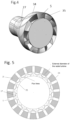
- Fig. 4 and Fig. 5 schematically show some details inside the machine.
- a mixed flow centrifugal impeller 1 including three-dimensional blades is present.
- the impeller is made of aluminum alloy or composite material with carbon fibers and titanium alloy.
- the impeller elaborate the incoming air imparting a radial and tangential acceleration, therefore increasing its kinetic and potential energy.
- a shroud 26, shaped according to the profile of the blades, is positioned with minimum radial clearance, 0.05 - 0.3 mm, to avoid circulation of compressed air at the tip of the blades.
- the impeller is mounted onto the shaft 2 with a central hole having a feature for torque transmission, such as a polygonal coupling or a splined profile, and a centering diameter to avoid excessive unbalancing during rotation.
- the shaft 2 is supported by two rolling bearings 3, respectively a ball bearing on the front, i.e. the one closest to the impeller, and cylindrical roller on the rear side.
- the shaft is mechanically connected to the turbine 3, which is shown with three stages in cascade, in particular to the rings that support the array of blades, via the turbine disk 29.
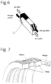
- Figure 7 shows a typical configuration of the blades of a radial outflow turbine with support rings connected to the turbine disk 29 via a flange.
- the bearings 3 of the shaft 2 are isolated from the external environment with a chamber, not shown in the figure, buffered with air taken downstream the impeller 1 according to a known technique.
- the bearings 3 and the shaft 2 are supported by a frame formed by an external ring 28 where openings are present, not shown in the figure, fluidly connected to the profile formed by the des-wirl vanes 5 and the conical struts 30 and 31, the latter including a thermal insulation, not shown in the figure, to shield the heat radiated from the turbine disk 29.
- the external ring 28 also incorporates the attachment points, not shown, of the engine to the aircraft structure according to a known technique.
- the vanes 5 are profiled to receive the compressed air from the impeller 1 with a tangential component of the velocity, i.e. perpendicular to the meridian plane of Fig 3 , which is progressively decreased up to the trailing edge of the vanes, 32, to increase the thrust.
- the surface of the vanes 5 has a three-dimensional shape as shown in figure 4 .
- the assembly formed by the vanes 5, the surface wall 34 - 35 and everything connected to them is mechanically and fluidly connected to the flange 28 with a set of screws 33.
- a portion of the air elaborated by the impeller 1 is bleeded, for example 6.5% by mass at 1.2 Bar, and distributed through appropriate openings 37 to several channels 19, fluidly separated by the wall 34, to the plenum 20 which distributes the air to the gas generator.
- the air partially compressed at 1.2 Bar is compressed by a first stage of centrifugal compressor comprising an impeller 6, a diffuser 7 and a vaned return channel 8 which feeds a second stage of centrifugal compressor comprising an impeller 9 and a diffuser 10.
- the two Impellers 6 and 9 are overhang mounted onto a shaft 23, rotary supported by two rolling bearings 22, and where the stages of the high pressure turbine are also mounted according to a known technique.
- the impellers are mechanically connected to the shaft by means of polygonal or splined features for torque transmission and centered radially on the shaft.
- the bearings 22 of the shaft 23 are mounted inside sumps which are in communication, via the channels 21 and 27, with the components of the engine external to the surface wall 34, where auxiliary piping systems, not shown in figure 3 , for lubrication and compressed air to buffer the engine cavities are present.
- the diffuser 16 is mechanically and fluidly connected via the transition piece 10 to the recuperator 11 formed by a plurality of exchangers positioned inside the vanes 5.
- the transition piece 10 distributes the flow of compressed air from an annular surface to the openings positioned in correspondence with the deswirl vanes 5.
- the compressed air from the recuperator 11 feeds the combustion chamber 14 passing through the supply channels 12 which are fluidly connected to the recuperator 11.
- the combustion chamber 14 is of the radial type with a distributor of fuel, for example kerosene or hydrogen, made with a rotating ring connected onto the shaft according to a known technique not shown in the figure.
- the fuel-air mixture is ignited at start-up by means of an ignition device positioned in the channel 38 which penetrate through the blades 5, without interfering with the air flow of the fan, until it reaches the area outside the wall 34 where the turbofan accessories, not shown in Fig. 3 , are mounted.
- the combustion chamber 14, according to a known technique, has holes and openings which allow the air to be appropriately distributed for the combustion process.
- the diaphragm 50 is mechanically and fluidly connected to the structure that supports the deswirl vanes 5 via a flange.
- the exhaust gases, once expanded in the radial turbine 16, are fed into a transition piece 17 which distributes the flow from an annular surface to openings positioned in correspondence with the vanes 5.
- the hot gas flow at 500-600°C passes through the internal volume of the deswirl vanes 5 exchanging heat both with the flow of air coming from the fan in the channel 25, through the surfaces of the deswirl vanes 5, and with the flow of compressed air coming from the compressor inside the recuperator 5 as shown in Fig. 6 .
- the combustion gases that flow inside the vanes 5 heat up the air flow that passes through the channel 25 up to the vane trailing edge 32 which has an opening, not shown in the drawing, to discharge the gas generator combustion gases into the environment.
- the advantages of the present invention are based on a turbofan architecture which allows the combustion gases of the gas generator to be simultanuelsy used to supercharge the fan air flow and to heat up the compressor air flow before entering the combustion chamber .
- This engine architecture using a radial outflow turbine to drive the fan makes possible a compact design of a high by-pass ratio turbofan improving both the propulsive efficiency and thermodynamic efficiency of the gas turbine.
Landscapes
- Engineering & Computer Science (AREA)
- Chemical & Material Sciences (AREA)
- Combustion & Propulsion (AREA)
- Mechanical Engineering (AREA)
- General Engineering & Computer Science (AREA)
- Structures Of Non-Positive Displacement Pumps (AREA)
Applications Claiming Priority (1)
| Application Number | Priority Date | Filing Date | Title |
|---|---|---|---|
| IT102023000013617A IT202300013617A1 (it) | 2023-07-07 | 2023-07-07 | Turboventola migliorata con ciclo recuperativo |
Publications (1)
| Publication Number | Publication Date |
|---|---|
| EP4484723A1 true EP4484723A1 (fr) | 2025-01-01 |
Family
ID=88291191
Family Applications (1)
| Application Number | Title | Priority Date | Filing Date |
|---|---|---|---|
| EP24184994.2A Pending EP4484723A1 (fr) | 2023-07-07 | 2024-06-27 | Turbosoufflante suralimentée à cycle de récupération |
Country Status (2)
| Country | Link |
|---|---|
| EP (1) | EP4484723A1 (fr) |
| IT (1) | IT202300013617A1 (fr) |
Citations (7)
| Publication number | Priority date | Publication date | Assignee | Title |
|---|---|---|---|---|
| US4916894A (en) | 1989-01-03 | 1990-04-17 | General Electric Company | High bypass turbofan engine having a partially geared fan drive turbine |
| WO2002038938A1 (fr) * | 2000-11-10 | 2002-05-16 | Kovac Marek | Reacteur a turbine a gaz avec derivation et procede de refroidissement pour fluide caloporteur |
| EP2551485A2 (fr) * | 2011-07-26 | 2013-01-30 | United Technologies Corporation | Moteur à turbine à gaz avec section ventilateur entraîné central arrière |
| US8387357B2 (en) | 2008-08-12 | 2013-03-05 | Pratt & Whitney | Recuperated bypass turbine engine |
| WO2015088606A2 (fr) * | 2013-12-13 | 2015-06-18 | United Technologies Corporation | Architecture pour un système de propulsion axialement compact et à performances élevées |
| EP3730768A1 (fr) | 2017-03-06 | 2020-10-28 | Rolls-Royce plc | Turboréacteur à engrenages |
| US20210017911A1 (en) | 2019-07-18 | 2021-01-21 | Rolls-Royce Plc | Turbofan gas turbine engine with gearbox |
-
2023
- 2023-07-07 IT IT102023000013617A patent/IT202300013617A1/it unknown
-
2024
- 2024-06-27 EP EP24184994.2A patent/EP4484723A1/fr active Pending
Patent Citations (7)
| Publication number | Priority date | Publication date | Assignee | Title |
|---|---|---|---|---|
| US4916894A (en) | 1989-01-03 | 1990-04-17 | General Electric Company | High bypass turbofan engine having a partially geared fan drive turbine |
| WO2002038938A1 (fr) * | 2000-11-10 | 2002-05-16 | Kovac Marek | Reacteur a turbine a gaz avec derivation et procede de refroidissement pour fluide caloporteur |
| US8387357B2 (en) | 2008-08-12 | 2013-03-05 | Pratt & Whitney | Recuperated bypass turbine engine |
| EP2551485A2 (fr) * | 2011-07-26 | 2013-01-30 | United Technologies Corporation | Moteur à turbine à gaz avec section ventilateur entraîné central arrière |
| WO2015088606A2 (fr) * | 2013-12-13 | 2015-06-18 | United Technologies Corporation | Architecture pour un système de propulsion axialement compact et à performances élevées |
| EP3730768A1 (fr) | 2017-03-06 | 2020-10-28 | Rolls-Royce plc | Turboréacteur à engrenages |
| US20210017911A1 (en) | 2019-07-18 | 2021-01-21 | Rolls-Royce Plc | Turbofan gas turbine engine with gearbox |
Also Published As
| Publication number | Publication date |
|---|---|
| IT202300013617A1 (it) | 2025-01-07 |
Similar Documents
| Publication | Publication Date | Title |
|---|---|---|
| CA1233325A (fr) | Turbne de production d'energie, a mouvement contrarotatif | |
| US3703081A (en) | Gas turbine engine | |
| US7231767B2 (en) | Forced air cooling system | |
| US20190323433A1 (en) | Gas turbine engine | |
| JP2008111437A (ja) | ガスタービンエンジン組立体 | |
| CN102305152A (zh) | 混排航空发动机 | |
| JPH0681883B2 (ja) | 反対廻りの回転子を持つ動力タービンを有するガスタービン機関 | |
| US4302148A (en) | Gas turbine engine having a cooled turbine | |
| CN115788679B (zh) | 废热回收系统 | |
| EP4219920B1 (fr) | Moteur à turbine à gaz et procédé de fonctionnement d'un ensemble échangeur de chaleur pour moteur à turbine à gaz | |
| CN110608099B (zh) | 具有一体式空气循环机的燃气涡轮发动机 | |
| EP3290636B1 (fr) | Système de refroidissement de courant multi-air | |
| CN120100531A (zh) | 用于具有阻尼元件的发动机的开式风扇转子的可变节距翼型件组件 | |
| CN119062447A (zh) | 燃气涡轮发动机 | |
| CN113279857B (zh) | 一种适用于无人飞行器的高推重比燃气涡轮发生器 | |
| CN114076035A (zh) | 具有初级和次级气流路径的空气涡轮启动器 | |
| US3462953A (en) | Gas turbine jet propulsion engine | |
| WO2013113324A1 (fr) | Turbine à gaz dotée d'un carter rotatif | |
| US10519976B2 (en) | Fluid diodes with ridges to control boundary layer in axial compressor stator vane | |
| CN121001929A (zh) | 具有第三流的燃气涡轮发动机 | |
| EP4484723A1 (fr) | Turbosoufflante suralimentée à cycle de récupération | |
| GB2042643A (en) | Cooled Gas Turbine Engine | |
| CN118532280A (zh) | 减小边界层引起的畸变的具有开式风扇的发动机 | |
| US12209594B2 (en) | Turbomachine structure with three air flows | |
| EP4660432A1 (fr) | Turboréacteur à double flux contrarotatif amélioré |
Legal Events
| Date | Code | Title | Description |
|---|---|---|---|
| PUAI | Public reference made under article 153(3) epc to a published international application that has entered the european phase |
Free format text: ORIGINAL CODE: 0009012 |
|
| STAA | Information on the status of an ep patent application or granted ep patent |
Free format text: STATUS: THE APPLICATION HAS BEEN PUBLISHED |
|
| AK | Designated contracting states |
Kind code of ref document: A1 Designated state(s): AL AT BE BG CH CY CZ DE DK EE ES FI FR GB GR HR HU IE IS IT LI LT LU LV MC ME MK MT NL NO PL PT RO RS SE SI SK SM TR |
|
| STAA | Information on the status of an ep patent application or granted ep patent |
Free format text: STATUS: REQUEST FOR EXAMINATION WAS MADE |
|
| 17P | Request for examination filed |
Effective date: 20250619 |