EP4484782A1 - Linearführungseinrichtung - Google Patents
Linearführungseinrichtung Download PDFInfo
- Publication number
- EP4484782A1 EP4484782A1 EP23756079.2A EP23756079A EP4484782A1 EP 4484782 A1 EP4484782 A1 EP 4484782A1 EP 23756079 A EP23756079 A EP 23756079A EP 4484782 A1 EP4484782 A1 EP 4484782A1
- Authority
- EP
- European Patent Office
- Prior art keywords
- holder
- guide
- shaft member
- hole
- connecting shaft
- Prior art date
- Legal status (The legal status is an assumption and is not a legal conclusion. Google has not performed a legal analysis and makes no representation as to the accuracy of the status listed.)
- Pending
Links
Images







Classifications
-
- F—MECHANICAL ENGINEERING; LIGHTING; HEATING; WEAPONS; BLASTING
- F16—ENGINEERING ELEMENTS AND UNITS; GENERAL MEASURES FOR PRODUCING AND MAINTAINING EFFECTIVE FUNCTIONING OF MACHINES OR INSTALLATIONS; THERMAL INSULATION IN GENERAL
- F16C—SHAFTS; FLEXIBLE SHAFTS; ELEMENTS OR CRANKSHAFT MECHANISMS; ROTARY BODIES OTHER THAN GEARING ELEMENTS; BEARINGS
- F16C29/00—Bearings for parts moving only linearly
- F16C29/12—Arrangements for adjusting play
-
- F—MECHANICAL ENGINEERING; LIGHTING; HEATING; WEAPONS; BLASTING
- F16—ENGINEERING ELEMENTS AND UNITS; GENERAL MEASURES FOR PRODUCING AND MAINTAINING EFFECTIVE FUNCTIONING OF MACHINES OR INSTALLATIONS; THERMAL INSULATION IN GENERAL
- F16C—SHAFTS; FLEXIBLE SHAFTS; ELEMENTS OR CRANKSHAFT MECHANISMS; ROTARY BODIES OTHER THAN GEARING ELEMENTS; BEARINGS
- F16C29/00—Bearings for parts moving only linearly
- F16C29/005—Guide rails or tracks for a linear bearing, i.e. adapted for movement of a carriage or bearing body there along
-
- F—MECHANICAL ENGINEERING; LIGHTING; HEATING; WEAPONS; BLASTING
- F16—ENGINEERING ELEMENTS AND UNITS; GENERAL MEASURES FOR PRODUCING AND MAINTAINING EFFECTIVE FUNCTIONING OF MACHINES OR INSTALLATIONS; THERMAL INSULATION IN GENERAL
- F16C—SHAFTS; FLEXIBLE SHAFTS; ELEMENTS OR CRANKSHAFT MECHANISMS; ROTARY BODIES OTHER THAN GEARING ELEMENTS; BEARINGS
- F16C29/00—Bearings for parts moving only linearly
- F16C29/001—Bearings for parts moving only linearly adjustable for alignment or positioning
-
- F—MECHANICAL ENGINEERING; LIGHTING; HEATING; WEAPONS; BLASTING
- F16—ENGINEERING ELEMENTS AND UNITS; GENERAL MEASURES FOR PRODUCING AND MAINTAINING EFFECTIVE FUNCTIONING OF MACHINES OR INSTALLATIONS; THERMAL INSULATION IN GENERAL
- F16C—SHAFTS; FLEXIBLE SHAFTS; ELEMENTS OR CRANKSHAFT MECHANISMS; ROTARY BODIES OTHER THAN GEARING ELEMENTS; BEARINGS
- F16C29/00—Bearings for parts moving only linearly
- F16C29/04—Ball or roller bearings
-
- F—MECHANICAL ENGINEERING; LIGHTING; HEATING; WEAPONS; BLASTING
- F16—ENGINEERING ELEMENTS AND UNITS; GENERAL MEASURES FOR PRODUCING AND MAINTAINING EFFECTIVE FUNCTIONING OF MACHINES OR INSTALLATIONS; THERMAL INSULATION IN GENERAL
- F16C—SHAFTS; FLEXIBLE SHAFTS; ELEMENTS OR CRANKSHAFT MECHANISMS; ROTARY BODIES OTHER THAN GEARING ELEMENTS; BEARINGS
- F16C29/00—Bearings for parts moving only linearly
- F16C29/04—Ball or roller bearings
- F16C29/041—Ball or roller bearings having rollers crossed within a row
-
- F—MECHANICAL ENGINEERING; LIGHTING; HEATING; WEAPONS; BLASTING
- F16—ENGINEERING ELEMENTS AND UNITS; GENERAL MEASURES FOR PRODUCING AND MAINTAINING EFFECTIVE FUNCTIONING OF MACHINES OR INSTALLATIONS; THERMAL INSULATION IN GENERAL
- F16C—SHAFTS; FLEXIBLE SHAFTS; ELEMENTS OR CRANKSHAFT MECHANISMS; ROTARY BODIES OTHER THAN GEARING ELEMENTS; BEARINGS
- F16C29/00—Bearings for parts moving only linearly
- F16C29/04—Ball or roller bearings
- F16C29/045—Ball or roller bearings having rolling elements journaled in one of the moving parts
-
- F—MECHANICAL ENGINEERING; LIGHTING; HEATING; WEAPONS; BLASTING
- F16—ENGINEERING ELEMENTS AND UNITS; GENERAL MEASURES FOR PRODUCING AND MAINTAINING EFFECTIVE FUNCTIONING OF MACHINES OR INSTALLATIONS; THERMAL INSULATION IN GENERAL
- F16C—SHAFTS; FLEXIBLE SHAFTS; ELEMENTS OR CRANKSHAFT MECHANISMS; ROTARY BODIES OTHER THAN GEARING ELEMENTS; BEARINGS
- F16C29/00—Bearings for parts moving only linearly
- F16C29/12—Arrangements for adjusting play
- F16C29/123—Arrangements for adjusting play using elastic means
-
- F—MECHANICAL ENGINEERING; LIGHTING; HEATING; WEAPONS; BLASTING
- F16—ENGINEERING ELEMENTS AND UNITS; GENERAL MEASURES FOR PRODUCING AND MAINTAINING EFFECTIVE FUNCTIONING OF MACHINES OR INSTALLATIONS; THERMAL INSULATION IN GENERAL
- F16C—SHAFTS; FLEXIBLE SHAFTS; ELEMENTS OR CRANKSHAFT MECHANISMS; ROTARY BODIES OTHER THAN GEARING ELEMENTS; BEARINGS
- F16C43/00—Assembling bearings
- F16C43/04—Assembling rolling-contact bearings
-
- F—MECHANICAL ENGINEERING; LIGHTING; HEATING; WEAPONS; BLASTING
- F16—ENGINEERING ELEMENTS AND UNITS; GENERAL MEASURES FOR PRODUCING AND MAINTAINING EFFECTIVE FUNCTIONING OF MACHINES OR INSTALLATIONS; THERMAL INSULATION IN GENERAL
- F16C—SHAFTS; FLEXIBLE SHAFTS; ELEMENTS OR CRANKSHAFT MECHANISMS; ROTARY BODIES OTHER THAN GEARING ELEMENTS; BEARINGS
- F16C2226/00—Joining parts; Fastening; Assembling or mounting parts
- F16C2226/50—Positive connections
- F16C2226/60—Positive connections with threaded parts, e.g. bolt and nut connections
-
- F—MECHANICAL ENGINEERING; LIGHTING; HEATING; WEAPONS; BLASTING
- F16—ENGINEERING ELEMENTS AND UNITS; GENERAL MEASURES FOR PRODUCING AND MAINTAINING EFFECTIVE FUNCTIONING OF MACHINES OR INSTALLATIONS; THERMAL INSULATION IN GENERAL
- F16C—SHAFTS; FLEXIBLE SHAFTS; ELEMENTS OR CRANKSHAFT MECHANISMS; ROTARY BODIES OTHER THAN GEARING ELEMENTS; BEARINGS
- F16C2240/00—Specified values or numerical ranges of parameters; Relations between them
- F16C2240/30—Angles, e.g. inclinations
-
- F—MECHANICAL ENGINEERING; LIGHTING; HEATING; WEAPONS; BLASTING
- F16—ENGINEERING ELEMENTS AND UNITS; GENERAL MEASURES FOR PRODUCING AND MAINTAINING EFFECTIVE FUNCTIONING OF MACHINES OR INSTALLATIONS; THERMAL INSULATION IN GENERAL
- F16C—SHAFTS; FLEXIBLE SHAFTS; ELEMENTS OR CRANKSHAFT MECHANISMS; ROTARY BODIES OTHER THAN GEARING ELEMENTS; BEARINGS
- F16C2240/00—Specified values or numerical ranges of parameters; Relations between them
- F16C2240/40—Linear dimensions, e.g. length, radius, thickness, gap
- F16C2240/46—Gap sizes or clearances
-
- F—MECHANICAL ENGINEERING; LIGHTING; HEATING; WEAPONS; BLASTING
- F16—ENGINEERING ELEMENTS AND UNITS; GENERAL MEASURES FOR PRODUCING AND MAINTAINING EFFECTIVE FUNCTIONING OF MACHINES OR INSTALLATIONS; THERMAL INSULATION IN GENERAL
- F16C—SHAFTS; FLEXIBLE SHAFTS; ELEMENTS OR CRANKSHAFT MECHANISMS; ROTARY BODIES OTHER THAN GEARING ELEMENTS; BEARINGS
- F16C2300/00—Application independent of particular apparatuses
- F16C2300/02—General use or purpose, i.e. no use, purpose, special adaptation or modification indicated or a wide variety of uses mentioned
-
- F—MECHANICAL ENGINEERING; LIGHTING; HEATING; WEAPONS; BLASTING
- F16—ENGINEERING ELEMENTS AND UNITS; GENERAL MEASURES FOR PRODUCING AND MAINTAINING EFFECTIVE FUNCTIONING OF MACHINES OR INSTALLATIONS; THERMAL INSULATION IN GENERAL
- F16C—SHAFTS; FLEXIBLE SHAFTS; ELEMENTS OR CRANKSHAFT MECHANISMS; ROTARY BODIES OTHER THAN GEARING ELEMENTS; BEARINGS
- F16C29/00—Bearings for parts moving only linearly
- F16C29/04—Ball or roller bearings
- F16C29/048—Ball or roller bearings with thin walled races, e.g. tracks of sheet metal
Definitions
- the present invention relates to a linear guide device including a guide rail having a linearly extended shape and a traveling body configured to travel along the guide rail.
- the guide rail includes a pair of guide portions facing in a first direction orthogonal to a longitudinal direction and an opening portion opened toward one side in a second direction orthogonal to both the longitudinal direction and the first direction.
- Each of the guide portions includes a first guide surface which is located farther from the opening portion and a second guide surface which is located nearer to the opening portion.
- the first guide surface of one of the pair of guide portions is inclined to separate from the first guide surface of the other of the pair of guide portions toward the opening portion.
- the second guide surface of one of the pair of guide portions is inclined to approach to the second guide surface of the other of the pair of guide portions toward the opening portion.
- the traveling body of the linear guide device includes a plurality of rollers rolling on the first guide surface of the pair of guide portions and a plurality of rollers rolling on the second guide surface of the pair of guide portions.
- Patent Document 1 Japanese Unexamined Patent Application Publication No. 2000-320228 discloses an improved linear guide device as a prior art document.
- the traveling body includes a holder divided into two parts (i.e., a main holder and a sub holder).
- a first roller rolling on the first guide surface is rotatably supported on the main holder.
- a second roller rolling on the second guide surface is rotatably supported on the sub holder.
- the main holder and the sub holder are connected to each other so that the interval between the main holder and the sub holder in the second direction can be adjusted by a plurality of adjustment screws.
- the first and second rollers can be adjusted to abut on the first and second guide surfaces respectively by the plurality of adjustment screws. Note that the guide surface to which the first roller of the main holder is abutted and the guide surface to which the second roller of the sub holder is abutted can be reversed to each other in the above described linear guide device.
- the installing position of the rollers of the traveling body includes an error.
- a part of the rollers abuts on the guide surface strongly while the other parts of the rollers abut on the guide surface only slightly due to the error in some cases.
- Patent Document 1 although the abutment of the rollers to the guide surfaces can be adjusted by adjusting the interval between the main holder and the sub holder, it is difficult to compensate a minute installation error of the rollers.
- a linear guide device of the present invention includes: a guide rail having a linearly extended shape; and a traveling body configured to travel along the guide rail, wherein the guide rail includes a pair of guide portions which are arranged to face each other in a first direction orthogonal to a longitudinal direction of the guide rail, the guide rail includes an opening portion opened toward one side in a second direction orthogonal to both the longitudinal direction and the first direction, each of the pair of guide portions includes a first guide surface and a second guide surface, the first surface being located farther from the opening portion than the second guide surface, the second guide surface being located nearer to the opening portion than the first guide surface, the first guide surface of one of the pair of guide portions is inclined to separate from the first guide surface of the other of the pair of guide portions toward the opening portion, the second guide surface of one of the pair of guide portions is inclined to approach to the first guide surface of the other of the pair of guide portions toward the opening portion, the traveling body includes a first holder and a second holder,
- the relative position of the first and second holders in the first direction is changed by the abutment between the first/second guide surfaces of the guide rail and the first/second rollers against the frictional resistance of the friction imparting portion. Consequently, a manufacturing error of the traveling body including an assembling error of the rollers is automatically compensated.
- the abutment state of the first and second rollers to the first and second guide surfaces can be optimized.
- the traveling body can be traveled stably.
- the relative position of the first and the second holders is restricted by the frictional resistance at the friction imparting portion.
- the first and second rollers can be rolled on the first and second guide surfaces stably.
- the connecting shaft member is formed by a single member, and the first holder and the second holder are connected to each other by the connecting shaft member so that the first holder and the second holder can be relatively displaced in the first direction and relatively rotated around the connecting shaft member.
- the connecting shaft member is inserted into a hole of a connecting portion of the first holder and another hole of another connecting portion of the second holder, at least one of the holes of the first holder and the second holder is a through hole, and a clearance is formed between an inner periphery of the through hole and an outer periphery of the connecting shaft member so that the first holder and the second holder can be relatively moved in the first direction.
- the connecting portions connecting the first holder and the second holder are connected to each other by the connecting shaft member while facing to each other via a gap formed in the second direction and receiving a force approaching to each other, the first holder and the second holder are in contact with each other at an abutting portion separating from the connecting portions, and the abutting portion is provided as the friction imparting portion.
- the first holder includes a base portion which has a plate shape arranged on an outside of the guide rail
- the second holder includes abutting pieces on both sides in the first direction, the abutting pieces being inclined with respect to the base portion, and the abutting portion between the abutting piece and the base portion is provided as the friction imparting portion.
- an end portion of the abutting piece is thinner than the other portion of the abutting piece.
- the frictional resistance can be obtained more certainly in the abutting portion at a desired level.
- the connecting shaft member includes a shaft portion provided with a male screw and a head portion formed on one end of the shaft portion, at least one of the holes of the first holder and the second holder is provided as a through hole, and the other of the holes of the first holder and the second holder is provided as a screw hole, the shaft portion of the connecting shaft member is inserted into the through hole and screwed into the screw hole so that the first holder and the second holder are connected to each other and the first holder and the second holder receive a force approaching to each other.
- the level of the frictional resistance applied by the friction imparting portion can be optimally controlled by adjusting the amount of screwing the connecting shaft member.
- all rollers including the first roller and the second roller are symmetrically with respect to a first reference line passing through the connecting shaft member and extending in the longitudinal direction and symmetrically with respect to a second reference line passing through the connecting shaft member and extending in the first direction.
- the traveling body can be travelled more stably.
- the manufacturing error of the traveling body including the assembling error of the rollers can be automatically compensated when incorporating the traveling body in the guide rail.
- the abutment state of the first and second rollers to the first and second guide surfaces can be optimized.
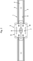
- the linear guide device includes a guide rail 1 having a linearly extended shape (i.e., long shape) and a traveling body 5 configured to travel along a longitudinal direction of the guide rail 1.
- the guide rail 1 is horizontally arranged on the lower side while the traveling body 5 is arranged on the upper side.
- the longitudinal direction of the guide rail 1 is also referred to as a travelling direction.
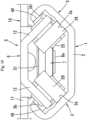
- the guide rail 1 includes a base portion 2 which has a long plate shape, a pair of guide portions 3 which have a long shape and are arranged to face each other in a right-left direction or a width direction (i.e., first direction orthogonal to the longitudinal direction) of the guide rail 1, and an opening portion 4 formed between the pair of guide portions 3.
- the base portion 2 and the opening portion 4 are arranged to face each other in an up-down direction (i.e., second direction orthogonal to both the longitudinal direction and the first direction).
- the base portion 2 is fixed to the upper surface of the first object such as a static object.
- Each of the guide portions 3 has a bent plate shape.
- the inner surfaces of each of the guide portions 3 are provided as a flat first guide surface 3a and a flat second guide surface 3b.
- the first guide surface 3a which is located at the lower side and nearer to the base portion 2 is connected to the base portion with an obtuse angle of 135°.
- the second guide surface 3b which is located at the upper side and nearer to the opening portion 4 is connected to the first guide surface 3a at an angle of 90°.
- the first guide surface 3a of one of the pair of guide portions 3 is inclined to separate from the first guide surface 3a of the other of the pair of guide portions 3 toward the opening portion 4.
- the second guide surface 3b of one of the pair of guide portions 3 is inclined to approach to the second guide surface 3b of the other of the pair of guide portions 3 toward the opening portion 4.
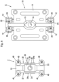
- the traveling body 5 is formed by connecting a main assembly 6 (first assembly) and a sub assembly 7 (second assembly) with a single connecting shaft member 8 at the center of the main assembly 6 and the sub assembly 7.
- the main assembly 6 is configured to support a plurality of (e.g. four) rollers 20 (first rollers) by a main holder 10 (first holder) so that the rollers 20 can be rotated.
- the sub assembly 7 is configured to support a plurality of (e.g. four) rollers 40 (second rollers) by a sub holder 30 (second holder) so that the rollers 40 can be rotated.
- the main holder 10 includes a base portion 11 having a rectangular plate shape and two pairs of roller holding portions 12 formed on both end portions of the base portion 11 in the travelling direction.
- the base portion 11 is configured to be fixed to the lower surface of the second object such as a moving object.
- the roller holding portions 12 of each pair face to each other in the right-left direction.
- the roller holding portions 12 of each pair are inclined with respect to the base portion 11 at an angle of 45° and extended below to separate from each other.
- the roller 20 is connected to each of the roller holding portions 12 by a roller shaft member 25 so that the roller 20 can be rotated.
- the roller 20 includes an inner ring portion and an outer ring portion rotatably supported by the inner ring portion via a bearing.
- the inner ring portion of the roller 20 is fixed to the roller holding portion 12 by the roller shaft member 25 inserted through a hole of the roller holding portion 12.
- the outer ring portion of the roller 20 can be rotated around the roller shaft member 25.
- the rotation axes of the rollers 20 supported by the pair of the roller holding portions 12 are crossed with each other at an angle of 90°.
- a boss portion 15 (connecting portion) protruded downward is formed on a center portion of the base portion 11 of the main holder 10.
- a through hole 16 (hole) is formed on the boss portion 15.
- the positions of the four rollers 20 are symmetrical to each other with respect to a reference line passing through the through hole 16 and extending in the travelling direction and a reference line passing through the through hole 16 and extending in the right-left direction.
- the through hole 16 is located at the center of a virtual rectangle formed by arranging the four rollers 20 at four corners.
- the connecting shaft member 8 is configured to be inserted in the through hole 16.
- the sub holder 30 includes a base portion 31 extending in the longitudinal direction of the guide rail 1 and a pair of plate-shaped pieces 32 protruded upward while separating from each other at an angle of 45° from both left and right edges of the base portion 31.
- the both end portions of each of the plate-shaped pieces 32 in the longitudinal direction of the guide rail are provided as roller holding portions 33.
- the roller 40 (second roller) is supported on each of the roller holding portions 33 so that the roller 40 can be rotated by a roller shaft member 45. Consequently, two pairs of rollers 40 facing in the right-left direction are arranged while being separated in the travelling direction.
- the rotation axes of the rollers 40 are crossed with each other at an angle of 90°.
- An intermediate portion of the plate-shaped piece 32 of the sub holder 30 is provided as an abutting piece 34.
- An end portion 34a of the abutting piece 34 is divided into two and formed thinner than the other portions of the abutting piece 34. The operation of the abutting piece 34 will be detailed later.
- a boss portion 35 (connecting portion) is formed on a center portion of the base portion 31 of the sub holder 30 in the longitudinal direction.
- a screw hole 36 (hole) is formed on the boss portion 35.
- the positions of the four rollers 40 are symmetrical to each other with respect to a reference line passing through the screw hole 36 and extending in the travelling direction and a reference line passing through the screw hole 36 and extending in the right-left direction.
- the screw hole 36 is located at the center of a virtual rectangle formed by arranging the four rollers 40 at four corners.
- the connecting shaft member 8 is configured to be screwed in the screw hole 36.
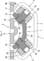
- the main assembly 6 and the sub assembly 7 constituting the above described configuration are connected to each other at only one point by the connecting shaft member 8 extending in the up-down direction. Consequently, the traveling body 5 is assembled.
- the connecting shaft member 8 includes a shaft portion 8a provided with a male screw on the outer periphery and a head portion 8b having a larger diameter.
- the main holder 10 and the sub holder 20 are aligned with each other so that the through hole 16 and the screw hole 36 are coaxial with each other.
- the shaft portion 8a of the connecting shaft member 8 is inserted through the through hole 16 and then the shaft portion 8a is screwed into the screw hole 36.
- the main holder 10 and the sub holder 20 are connected to each other.
- the main assembly 6 and the sub assembly 7 are connected to each other.
- the outer diameter of the shaft portion 8a of the connecting shaft member 8 is smaller than the inner diameter of the through hole 16.
- a clearance D is formed between the shaft portion 8a and the through hole 16.
- the above described clearance D is minute.
- the clearance D is approximately 0.2 to 0.3 mm.
- the end portion 34a of the abutting piece 34 of the sub holder 30 abuts on the base portion 11 of the main holder 10.
- the above described abutting portion is shown as the reference numeral P.
- the boss portions 15, 35 receive the force in the direction of approaching to each other.
- the abutting piece 34 (in particular, the end portion 34a which is the thinner portion) is elastically deformed so as to contact with the base portion 11 with an elastic force.
- the above described abutting portion P is provided as the friction imparting portion for achieving the later described function.
- the connecting shaft member 8 is screwed into the screw hole 36 as described above, the connecting shaft member 8 is fixed to the boss portion 35 of the sub holder 30 by an adhesive or the like.
- the lower surface of the boss portion 15 of the main holder 10 and the upper surface of the boss portion 35 of the sub holder 30 are not in contact with each other.
- a gap S1 is formed between the boss portion 15 and the boss portion 35.
- the inclined walls of the boss portion 15 of the main holder 10 located at both sides in the width direction and a pair of the plate-shaped pieces 32 of the sub holder 30 are not in contact with each other.
- a gap S2 is formed between the inclined walls and the pair of the plate-shaped pieces 32.
- the traveling body 5 having the above described configurations is incorporated from the end of the guide rail 1.
- the base portion 11 of the main holder 10 of the main assembly 6 is arranged above the guide rail 1, and the roller holding portion 12 and the rollers 20 of the main holder 10 and the sub assembly 7 are housed in the guide rail 1.
- the rollers 20 of the main assembly 6 abut on the first guide surface 3a of the guide rail 1.
- the rollers 40 of the sub assembly 7 abut on the second guide surface 3b of the guide rail 1. Consequently, when the traveling body 5 travels along the guide rail 1, the rollers 20 roll on the first guide surface 3a and the rollers 40 roll on the second guide surface 3b.
- the totally eight rollers 20, 40 are arranged on the positions symmetrical to each other with respect to the above described two reference lines. Thus, the rollers 20, 40 can be traveled stably.
- the rollers are divided into one roller group comprised of four rollers 20 supported by the main holder 10 and the other roller group comprised of four rollers 40 supported by the sub holder 30.
- the main holder 10 and the sub holder 30 can be relatively rotated around the connecting shaft member 8.
- the main holder 10 and the sub holder 30 can be relatively moved in the right-left direction since the clearance D is formed between the connecting shaft member 8 and the through hole 16.
- the traveling body 5 When the traveling body 5 is incorporated in the guide rail 1, since the guide surfaces 3a, 3b of the guide rail 1 and the rollers 20, 40 are abutted to each other, the first and second holders are relatively rotated and relatively moved in the right-left direction against the frictional resistance generated at the abutting portion P. Consequently, the manufacturing error of the traveling body 5 including the assembling error of the rollers 20, 40 is automatically compensated. Thus, the abutment state of the rollers 20, 40 to the guide surfaces 3a, 3b can be optimized. As a result, the traveling body can be travelled stably.
- the frictional resistance generated by the abutment between the abutting piece 34 of the sub holder 30 and the base portion 11 of the main holder 10 with elasticity at the abutting portion P is relatively large.
- the main holder 10 and the sub holder 30 can be relatively rotated and relatively moved in the right-left direction when the traveling body 5 is incorporated in the guide rail 1.
- the relative rotation of the holders 10, 30 and the relative movement of the holders 10, 30 in the right-left direction are restricted by the frictional resistance generated at the abutting portion P.
- the rollers 20, 40 can be rolled on the guide surfaces 3a, 3b stably.
- the main holder 10 and the sub holder 30 are connected to each other by screwing the connecting shaft member 8 into the screw hole 36 of the sub holder 30.
- the strength of the frictional resistance at the abutting portion P can be adjusted by adjusting the amount of screwing the connecting shaft member 8.
- the sub assembly 7 includes a pair of rollers 40 and the pair of rollers 40 face to each other in the right-left direction sandwiching the connecting shaft member 8.
- the center portion of the pair of plate-shaped pieces 32 of the sub holder 30 in the travelling direction is provided as the roller holding portions 33 and both end portions of the pair of plate-shaped pieces 32 are provided as the abutting piece 34.
- the main assembly 6 includes three rollers 20 and the sub assembly 7 includes three rollers 40.
- the rollers 20, 40 form a pair to face each other in the right-left direction at three locations separating from each other in the travelling direction.
- two rollers 20 are arranged on the right side, and the two rollers 20 roll on the first guide surface 3a of the guide portions 3 located at the right side of the guide rail 1.
- the roller 20 is arranged on the left side, and the roller 20 rolls on the first guide surface 3a of the guide portions 3 located at the left side of the guide rail 1.
- rollers 40 are arranged on the left side, and the two rollers 40 roll on the second guide surface 3b of the guide portions 3 located at the left side of the guide rail 1.
- the roller 40 is arranged on the right side, and the roller 40 rolls on the second guide surface 3b of the guide portions 3 located at the right side of the guide rail 1.
- the positions of the totally six rollers 20, 40 are symmetrically with respect to a reference line passing through the center of the connecting shaft member 8 and extending in the travelling direction and symmetrically with respect to a reference line passing through the center of the connecting shaft member 8 and extending in the right-left direction.
- the pair of guide portions 3 of the guide rail 1 is curved in a C-shape in cross section and the first guide surface 3a and the second guide surface 3b form a concave surface.
- a cross-sectional contour of the other peripheral portion of the rollers 20, 40 forms a convex curve.
- the other configurations are same as those of the first to third embodiments.
- the present invention is not limited to the above described embodiments. Various forms can be adopted.
- the main holder and the sub holder can be connected to each other by a plurality of connecting shaft members.
- the through hole on the sub holder and form the screw hole on the main holder It is possible to form the through hole on the sub holder and form the screw hole on the main holder. It is also possible to connect the main holder and the sub holder to each other by forming the connecting shaft member in a pin shape without forming the screw and calking the both end portions in a state of being inserted into the through holes of the main holder and the sub holder, for example.
- first rollers rolling on the first guide surface are supported by the main holder (first holder) and the second rollers rolling on the second guide surface are supported by the sub holder (second holder) in the above described embodiment, it is possible to support the first rollers by the sub holder and support the second rollers by the main holder reversely.
- the guide rail is arranged on the lower side while the traveling body is arranged on the upper side in the above described embodiment, it is possible to arrange them reversely or arrange the guide rail vertically and fix the guide rail to a wallboard or the like.
- the present invention can be applied to the linear guide device.
Landscapes
- Engineering & Computer Science (AREA)
- General Engineering & Computer Science (AREA)
- Mechanical Engineering (AREA)
- Bearings For Parts Moving Linearly (AREA)
Applications Claiming Priority (2)
| Application Number | Priority Date | Filing Date | Title |
|---|---|---|---|
| JP2022024587 | 2022-02-21 | ||
| PCT/JP2023/001488 WO2023157551A1 (ja) | 2022-02-21 | 2023-01-19 | リニアガイド装置 |
Publications (2)
| Publication Number | Publication Date |
|---|---|
| EP4484782A1 true EP4484782A1 (de) | 2025-01-01 |
| EP4484782A4 EP4484782A4 (de) | 2026-03-11 |
Family
ID=87578331
Family Applications (1)
| Application Number | Title | Priority Date | Filing Date |
|---|---|---|---|
| EP23756079.2A Pending EP4484782A4 (de) | 2022-02-21 | 2023-01-19 | Linearführungseinrichtung |
Country Status (6)
| Country | Link |
|---|---|
| US (1) | US20250369477A1 (de) |
| EP (1) | EP4484782A4 (de) |
| JP (1) | JP7478909B2 (de) |
| KR (1) | KR20240136391A (de) |
| CN (1) | CN118742742A (de) |
| WO (1) | WO2023157551A1 (de) |
Families Citing this family (1)
| Publication number | Priority date | Publication date | Assignee | Title |
|---|---|---|---|---|
| WO2026023441A1 (ja) * | 2024-07-23 | 2026-01-29 | スガツネ工業株式会社 | リニアガイド装置 |
Family Cites Families (7)
| Publication number | Priority date | Publication date | Assignee | Title |
|---|---|---|---|---|
| US2383195A (en) * | 1943-10-06 | 1945-08-21 | Alfred E Horman | Woodworking machine carriage |
| US2602710A (en) * | 1949-03-31 | 1952-07-08 | Edwin E Gesner | Tool supporting carriage |
| DE8700310U1 (de) * | 1987-01-08 | 1988-05-05 | Friedrich Graepel AG, 4573 Löningen | Linearführung ein- und mehrgleisig, drehstabil und spieleinstellbar |
| JP3188729B2 (ja) * | 1991-06-05 | 2001-07-16 | 西部電機株式会社 | 精密スライド機構 |
| IT1312171B1 (it) * | 1999-04-09 | 2002-04-09 | Rollon S P A | Guida lineare per supportare un elemento scorrevole. |
| JP7124667B2 (ja) * | 2018-11-21 | 2022-08-24 | 日本精工株式会社 | 直動案内装置及び機械装置 |
| KR20210041707A (ko) * | 2019-10-08 | 2021-04-16 | 주식회사 위너 | 베어링 스크류 이송 장치의 주행블록 |
-
2023
- 2023-01-19 US US18/835,734 patent/US20250369477A1/en active Pending
- 2023-01-19 JP JP2023524330A patent/JP7478909B2/ja active Active
- 2023-01-19 WO PCT/JP2023/001488 patent/WO2023157551A1/ja not_active Ceased
- 2023-01-19 EP EP23756079.2A patent/EP4484782A4/de active Pending
- 2023-01-19 CN CN202380022782.6A patent/CN118742742A/zh active Pending
- 2023-01-19 KR KR1020247027184A patent/KR20240136391A/ko active Pending
Also Published As
| Publication number | Publication date |
|---|---|
| JP7478909B2 (ja) | 2024-05-07 |
| WO2023157551A1 (ja) | 2023-08-24 |
| US20250369477A1 (en) | 2025-12-04 |
| JPWO2023157551A1 (de) | 2023-08-24 |
| KR20240136391A (ko) | 2024-09-13 |
| CN118742742A (zh) | 2024-10-01 |
| EP4484782A4 (de) | 2026-03-11 |
Similar Documents
| Publication | Publication Date | Title |
|---|---|---|
| US10689850B2 (en) | System for mounting a plurality of panels | |
| WO1997025507B1 (en) | Sliding door corner connector | |
| EP4484782A1 (de) | Linearführungseinrichtung | |
| JPWO2008038472A1 (ja) | スライドレールユニット | |
| US8152378B2 (en) | Automatic-positioning linear guide | |
| US5249867A (en) | Linear motion guide unit assembly having a misalignment absorbing mechanism | |
| JP2001227614A (ja) | リニアアクチュエータ | |
| WO2019154698A1 (en) | Wing for an aircraft | |
| CN109552826B (zh) | 物品搬运设备 | |
| US20210381290A1 (en) | Suspension holder and frame unit thereof | |
| JPH08114222A (ja) | ローラー型直綿案内装置 | |
| GB2141795A (en) | Linear slide roller bearing unit | |
| US20250229729A1 (en) | Connecting member, trim strip assembly, and vehicle | |
| US10596926B2 (en) | Seat tracking system | |
| JP2010106934A5 (de) | ||
| JP2529952Y2 (ja) | 直動転がり案内ユニット | |
| JP7171999B1 (ja) | 転動案内装置 | |
| EP4074998A1 (de) | Rollführungsvorrichtung und öffnungs- und schliessmechanismus | |
| US5230568A (en) | Linear bearing | |
| US20250282564A1 (en) | Transport system | |
| US7257974B2 (en) | Deep-rolling roller head of a deep-rolling tool | |
| JP3646248B2 (ja) | ローラ連結体及びローラ案内装置 | |
| CN220646501U (zh) | 一种滑块机构及具有其的同步带滑块、自动化模组 | |
| CN216197380U (zh) | 一种滚动机构 | |
| JP2014119036A (ja) | 直動案内装置の設置構造 |
Legal Events
| Date | Code | Title | Description |
|---|---|---|---|
| STAA | Information on the status of an ep patent application or granted ep patent |
Free format text: STATUS: THE INTERNATIONAL PUBLICATION HAS BEEN MADE |
|
| PUAI | Public reference made under article 153(3) epc to a published international application that has entered the european phase |
Free format text: ORIGINAL CODE: 0009012 |
|
| STAA | Information on the status of an ep patent application or granted ep patent |
Free format text: STATUS: REQUEST FOR EXAMINATION WAS MADE |
|
| 17P | Request for examination filed |
Effective date: 20240917 |
|
| AK | Designated contracting states |
Kind code of ref document: A1 Designated state(s): AL AT BE BG CH CY CZ DE DK EE ES FI FR GB GR HR HU IE IS IT LI LT LU LV MC ME MK MT NL NO PL PT RO RS SE SI SK SM TR |
|
| DAV | Request for validation of the european patent (deleted) | ||
| DAX | Request for extension of the european patent (deleted) | ||
| A4 | Supplementary search report drawn up and despatched |
Effective date: 20260206 |
|
| RIC1 | Information provided on ipc code assigned before grant |
Ipc: F16C 29/12 20060101AFI20260202BHEP Ipc: F16C 29/04 20060101ALI20260202BHEP Ipc: F16C 29/00 20060101ALI20260202BHEP Ipc: F16C 43/04 20060101ALI20260202BHEP |