EP4484820A1 - Verfahren zur wartung von ausrüstungen - Google Patents
Verfahren zur wartung von ausrüstungen Download PDFInfo
- Publication number
- EP4484820A1 EP4484820A1 EP23779960.6A EP23779960A EP4484820A1 EP 4484820 A1 EP4484820 A1 EP 4484820A1 EP 23779960 A EP23779960 A EP 23779960A EP 4484820 A1 EP4484820 A1 EP 4484820A1
- Authority
- EP
- European Patent Office
- Prior art keywords
- valve
- hydrogen
- section
- flow path
- gas
- Prior art date
- Legal status (The legal status is an assumption and is not a legal conclusion. Google has not performed a legal analysis and makes no representation as to the accuracy of the status listed.)
- Pending
Links
Images



Classifications
-
- F—MECHANICAL ENGINEERING; LIGHTING; HEATING; WEAPONS; BLASTING
- F17—STORING OR DISTRIBUTING GASES OR LIQUIDS
- F17C—VESSELS FOR CONTAINING OR STORING COMPRESSED, LIQUEFIED OR SOLIDIFIED GASES; FIXED-CAPACITY GAS-HOLDERS; FILLING VESSELS WITH, OR DISCHARGING FROM VESSELS, COMPRESSED, LIQUEFIED, OR SOLIDIFIED GASES
- F17C9/00—Methods or apparatus for discharging liquefied or solidified gases from vessels not under pressure
-
- F—MECHANICAL ENGINEERING; LIGHTING; HEATING; WEAPONS; BLASTING
- F17—STORING OR DISTRIBUTING GASES OR LIQUIDS
- F17C—VESSELS FOR CONTAINING OR STORING COMPRESSED, LIQUEFIED OR SOLIDIFIED GASES; FIXED-CAPACITY GAS-HOLDERS; FILLING VESSELS WITH, OR DISCHARGING FROM VESSELS, COMPRESSED, LIQUEFIED, OR SOLIDIFIED GASES
- F17C13/00—Details of vessels or of the filling or discharging of vessels
-
- F—MECHANICAL ENGINEERING; LIGHTING; HEATING; WEAPONS; BLASTING
- F17—STORING OR DISTRIBUTING GASES OR LIQUIDS
- F17C—VESSELS FOR CONTAINING OR STORING COMPRESSED, LIQUEFIED OR SOLIDIFIED GASES; FIXED-CAPACITY GAS-HOLDERS; FILLING VESSELS WITH, OR DISCHARGING FROM VESSELS, COMPRESSED, LIQUEFIED, OR SOLIDIFIED GASES
- F17C13/00—Details of vessels or of the filling or discharging of vessels
- F17C13/04—Arrangement or mounting of valves
-
- F—MECHANICAL ENGINEERING; LIGHTING; HEATING; WEAPONS; BLASTING
- F17—STORING OR DISTRIBUTING GASES OR LIQUIDS
- F17D—PIPE-LINE SYSTEMS; PIPE-LINES
- F17D1/00—Pipe-line systems
- F17D1/02—Pipe-line systems for gases or vapours
- F17D1/04—Pipe-line systems for gases or vapours for distribution of gas
-
- F—MECHANICAL ENGINEERING; LIGHTING; HEATING; WEAPONS; BLASTING
- F17—STORING OR DISTRIBUTING GASES OR LIQUIDS
- F17C—VESSELS FOR CONTAINING OR STORING COMPRESSED, LIQUEFIED OR SOLIDIFIED GASES; FIXED-CAPACITY GAS-HOLDERS; FILLING VESSELS WITH, OR DISCHARGING FROM VESSELS, COMPRESSED, LIQUEFIED, OR SOLIDIFIED GASES
- F17C2205/00—Vessel construction, in particular mounting arrangements, attachments or identifications means
- F17C2205/03—Fluid connections, filters, valves, closure means or other attachments
- F17C2205/0302—Fittings, valves, filters, or components in connection with the gas storage device
- F17C2205/0323—Valves
-
- F—MECHANICAL ENGINEERING; LIGHTING; HEATING; WEAPONS; BLASTING
- F17—STORING OR DISTRIBUTING GASES OR LIQUIDS
- F17C—VESSELS FOR CONTAINING OR STORING COMPRESSED, LIQUEFIED OR SOLIDIFIED GASES; FIXED-CAPACITY GAS-HOLDERS; FILLING VESSELS WITH, OR DISCHARGING FROM VESSELS, COMPRESSED, LIQUEFIED, OR SOLIDIFIED GASES
- F17C2221/00—Handled fluid, in particular type of fluid
- F17C2221/01—Pure fluids
- F17C2221/012—Hydrogen
-
- F—MECHANICAL ENGINEERING; LIGHTING; HEATING; WEAPONS; BLASTING
- F17—STORING OR DISTRIBUTING GASES OR LIQUIDS
- F17C—VESSELS FOR CONTAINING OR STORING COMPRESSED, LIQUEFIED OR SOLIDIFIED GASES; FIXED-CAPACITY GAS-HOLDERS; FILLING VESSELS WITH, OR DISCHARGING FROM VESSELS, COMPRESSED, LIQUEFIED, OR SOLIDIFIED GASES
- F17C2221/00—Handled fluid, in particular type of fluid
- F17C2221/01—Pure fluids
- F17C2221/014—Nitrogen
-
- F—MECHANICAL ENGINEERING; LIGHTING; HEATING; WEAPONS; BLASTING
- F17—STORING OR DISTRIBUTING GASES OR LIQUIDS
- F17C—VESSELS FOR CONTAINING OR STORING COMPRESSED, LIQUEFIED OR SOLIDIFIED GASES; FIXED-CAPACITY GAS-HOLDERS; FILLING VESSELS WITH, OR DISCHARGING FROM VESSELS, COMPRESSED, LIQUEFIED, OR SOLIDIFIED GASES
- F17C2223/00—Handled fluid before transfer, i.e. state of fluid when stored in the vessel or before transfer from the vessel
- F17C2223/01—Handled fluid before transfer, i.e. state of fluid when stored in the vessel or before transfer from the vessel characterised by the phase
- F17C2223/0146—Two-phase
- F17C2223/0153—Liquefied gas, e.g. LPG, GPL
-
- F—MECHANICAL ENGINEERING; LIGHTING; HEATING; WEAPONS; BLASTING
- F17—STORING OR DISTRIBUTING GASES OR LIQUIDS
- F17C—VESSELS FOR CONTAINING OR STORING COMPRESSED, LIQUEFIED OR SOLIDIFIED GASES; FIXED-CAPACITY GAS-HOLDERS; FILLING VESSELS WITH, OR DISCHARGING FROM VESSELS, COMPRESSED, LIQUEFIED, OR SOLIDIFIED GASES
- F17C2223/00—Handled fluid before transfer, i.e. state of fluid when stored in the vessel or before transfer from the vessel
- F17C2223/01—Handled fluid before transfer, i.e. state of fluid when stored in the vessel or before transfer from the vessel characterised by the phase
- F17C2223/0146—Two-phase
- F17C2223/0153—Liquefied gas, e.g. LPG, GPL
- F17C2223/0161—Liquefied gas, e.g. LPG, GPL cryogenic, e.g. LNG, GNL, PLNG
-
- F—MECHANICAL ENGINEERING; LIGHTING; HEATING; WEAPONS; BLASTING
- F17—STORING OR DISTRIBUTING GASES OR LIQUIDS
- F17C—VESSELS FOR CONTAINING OR STORING COMPRESSED, LIQUEFIED OR SOLIDIFIED GASES; FIXED-CAPACITY GAS-HOLDERS; FILLING VESSELS WITH, OR DISCHARGING FROM VESSELS, COMPRESSED, LIQUEFIED, OR SOLIDIFIED GASES
- F17C2223/00—Handled fluid before transfer, i.e. state of fluid when stored in the vessel or before transfer from the vessel
- F17C2223/03—Handled fluid before transfer, i.e. state of fluid when stored in the vessel or before transfer from the vessel characterised by the pressure level
- F17C2223/033—Small pressure, e.g. for liquefied gas
-
- F—MECHANICAL ENGINEERING; LIGHTING; HEATING; WEAPONS; BLASTING
- F17—STORING OR DISTRIBUTING GASES OR LIQUIDS
- F17C—VESSELS FOR CONTAINING OR STORING COMPRESSED, LIQUEFIED OR SOLIDIFIED GASES; FIXED-CAPACITY GAS-HOLDERS; FILLING VESSELS WITH, OR DISCHARGING FROM VESSELS, COMPRESSED, LIQUEFIED, OR SOLIDIFIED GASES
- F17C2227/00—Transfer of fluids, i.e. method or means for transferring the fluid; Heat exchange with the fluid
- F17C2227/04—Methods for emptying or filling
- F17C2227/044—Methods for emptying or filling by purging
-
- F—MECHANICAL ENGINEERING; LIGHTING; HEATING; WEAPONS; BLASTING
- F17—STORING OR DISTRIBUTING GASES OR LIQUIDS
- F17C—VESSELS FOR CONTAINING OR STORING COMPRESSED, LIQUEFIED OR SOLIDIFIED GASES; FIXED-CAPACITY GAS-HOLDERS; FILLING VESSELS WITH, OR DISCHARGING FROM VESSELS, COMPRESSED, LIQUEFIED, OR SOLIDIFIED GASES
- F17C2250/00—Accessories; Control means; Indicating, measuring or monitoring of parameters
- F17C2250/04—Indicating or measuring of parameters as input values
- F17C2250/0404—Parameters indicated or measured
- F17C2250/043—Pressure
-
- F—MECHANICAL ENGINEERING; LIGHTING; HEATING; WEAPONS; BLASTING
- F17—STORING OR DISTRIBUTING GASES OR LIQUIDS
- F17C—VESSELS FOR CONTAINING OR STORING COMPRESSED, LIQUEFIED OR SOLIDIFIED GASES; FIXED-CAPACITY GAS-HOLDERS; FILLING VESSELS WITH, OR DISCHARGING FROM VESSELS, COMPRESSED, LIQUEFIED, OR SOLIDIFIED GASES
- F17C2250/00—Accessories; Control means; Indicating, measuring or monitoring of parameters
- F17C2250/04—Indicating or measuring of parameters as input values
- F17C2250/0404—Parameters indicated or measured
- F17C2250/0439—Temperature
-
- F—MECHANICAL ENGINEERING; LIGHTING; HEATING; WEAPONS; BLASTING
- F17—STORING OR DISTRIBUTING GASES OR LIQUIDS
- F17C—VESSELS FOR CONTAINING OR STORING COMPRESSED, LIQUEFIED OR SOLIDIFIED GASES; FIXED-CAPACITY GAS-HOLDERS; FILLING VESSELS WITH, OR DISCHARGING FROM VESSELS, COMPRESSED, LIQUEFIED, OR SOLIDIFIED GASES
- F17C2260/00—Purposes of gas storage and gas handling
- F17C2260/01—Improving mechanical properties or manufacturing
- F17C2260/015—Facilitating maintenance
-
- F—MECHANICAL ENGINEERING; LIGHTING; HEATING; WEAPONS; BLASTING
- F17—STORING OR DISTRIBUTING GASES OR LIQUIDS
- F17C—VESSELS FOR CONTAINING OR STORING COMPRESSED, LIQUEFIED OR SOLIDIFIED GASES; FIXED-CAPACITY GAS-HOLDERS; FILLING VESSELS WITH, OR DISCHARGING FROM VESSELS, COMPRESSED, LIQUEFIED, OR SOLIDIFIED GASES
- F17C2260/00—Purposes of gas storage and gas handling
- F17C2260/03—Dealing with losses
- F17C2260/031—Dealing with losses due to heat transfer
- F17C2260/032—Avoiding freezing or defrosting
-
- F—MECHANICAL ENGINEERING; LIGHTING; HEATING; WEAPONS; BLASTING
- F17—STORING OR DISTRIBUTING GASES OR LIQUIDS
- F17C—VESSELS FOR CONTAINING OR STORING COMPRESSED, LIQUEFIED OR SOLIDIFIED GASES; FIXED-CAPACITY GAS-HOLDERS; FILLING VESSELS WITH, OR DISCHARGING FROM VESSELS, COMPRESSED, LIQUEFIED, OR SOLIDIFIED GASES
- F17C2270/00—Applications
- F17C2270/01—Applications for fluid transport or storage
- F17C2270/0134—Applications for fluid transport or storage placed above the ground
- F17C2270/0136—Terminals
-
- F—MECHANICAL ENGINEERING; LIGHTING; HEATING; WEAPONS; BLASTING
- F17—STORING OR DISTRIBUTING GASES OR LIQUIDS
- F17C—VESSELS FOR CONTAINING OR STORING COMPRESSED, LIQUEFIED OR SOLIDIFIED GASES; FIXED-CAPACITY GAS-HOLDERS; FILLING VESSELS WITH, OR DISCHARGING FROM VESSELS, COMPRESSED, LIQUEFIED, OR SOLIDIFIED GASES
- F17C2270/00—Applications
- F17C2270/01—Applications for fluid transport or storage
- F17C2270/0165—Applications for fluid transport or storage on the road
- F17C2270/0168—Applications for fluid transport or storage on the road by vehicles
- F17C2270/0171—Trucks
Definitions
- the present disclosure relates to a maintenance method of equipment that handles liquefied hydrogen.
- Patent Literature 1 discloses a method of shipping LNG from an LNG receiving terminal tank and a device for this purpose.
- a lorry is connected to the LNG receiving terminal via a flexible hose.
- nitrogen gas flows from a nitrogen gas supply facility into the flexible hose, thereby purging the LNG remaining in the flexible hose and disconnecting the lorry from the LNG receiving terminal.
- Patent Literature 1 JP 5495713 B2
- An object of the present disclosure is to provide a maintenance method of equipment capable of preventing nitrogen gas from solidifying when the equipment is separated from a flow path of liquefied hydrogen.
- An equipment maintenance method is an equipment maintenance method in a flow path having a first valve, a second valve, equipment, a third valve, and a fourth valve disposed in order along a direction in which liquefied hydrogen flows, and includes: filling hydrogen gas between the first valve and the fourth valve in the flow path; filling nitrogen gas between the second valve and the third valve in the flow path from a state where the hydrogen gas is filled between the first valve and the fourth valve in the flow path; and decoupling and sealing the flow path between the second valve and the equipment and between the third valve and the equipment, and separating the equipment from the flow path with the nitrogen gas filled between the second valve and the third valve in the flow path.
- the present disclosure provides a maintenance method of equipment capable of preventing nitrogen gas from solidifying when the equipment is separated from a flow path of liquefied hydrogen.
- the equipment according to the present disclosure is a member or device that handles liquefied hydrogen.
- a description will be given based on an example in which a pump is used as the equipment.
- FIG. 1 is an overall schematic diagram of a liquefied hydrogen system 1S that is the subject of the present disclosure.
- the liquefied hydrogen system 1S includes a liquefied hydrogen tank 100, a hydrogen utilization facility 101, and a plurality of pumps 50.
- the liquefied hydrogen tank 100, the hydrogen utilization facility 101, and the plurality of pumps 50 are connected by a flow path LS.
- the liquefied hydrogen tank 100 is a tank that can store liquefied hydrogen, and is disposed on land.
- the liquefied hydrogen tank 100 is a ground-mounted flat-bottom tank.
- the hydrogen utilization facility 101 is a facility that utilizes the liquefied hydrogen stored in the liquefied hydrogen tank 100.
- the hydrogen utilization facility 101 includes a lorry that transports liquefied hydrogen.
- the plurality of pumps 50 has a function of sending the liquefied hydrogen stored in the liquefied hydrogen tank 100 to the hydrogen utilization facility 101. Note that as shown in FIG. 1 , in the present embodiment, the plurality of pumps 50 is arranged in parallel.
- the liquefied hydrogen system 1S further includes two attachment and detachment mechanisms 1. Each of the attachment and detachment mechanisms 1 separates a part including the pump 50 from the flow path LS when performing maintenance on the pump 50.
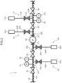
- FIG. 2 is an enlarged schematic diagram of the liquefied hydrogen system 1S according to the present embodiment, showing how liquefied hydrogen flows through the flow path LS.
- the attachment and detachment mechanism 1 includes a first valve 91, a second valve 92, a third valve 93 and a fourth valve 94.
- a section between the first valve 91 and the second valve 92 is referred to as a first section LS1
- a section between the second valve 92 and the pump 50 is referred to as a second section LS2
- a section between the pump 50 and the third valve 93 is referred to as a third section LS3
- a section between the third valve 93 and the fourth valve 94 is referred to as a fourth section LS4.
- the attachment and detachment mechanism 1 further includes a hydrogen supply and discharge unit 70, a hydrogen supply and discharge unit 71, a nitrogen supply unit 80, and a nitrogen discharge unit 81.
- Each supply and discharge unit supplies gas to the flow path LS and discharges gas from the flow path LS.
- the hydrogen supply and discharge unit 70 communicates with the first section LS1 and supplies hydrogen gas to the flow path LS.
- the hydrogen supply and discharge unit 70 discharges hydrogen gas from the first section LS1.
- the hydrogen supply and discharge unit 70 includes a hydrogen gas tank 70A, a flow path 70B, and a hydrogen valve 70C.
- the hydrogen gas tank 70A stores hydrogen gas.
- the flow path 70B communicates the hydrogen gas tank 70A with the first section LS1.
- the hydrogen valve 70C opens and closes the flow path 70B.
- the hydrogen supply and discharge unit 71 communicates with the fourth section LS4 and supplies hydrogen gas to the flow path LS. In addition, the hydrogen supply and discharge unit 71 discharges hydrogen gas from the fourth section LS4.
- the hydrogen supply and discharge unit 71 includes a hydrogen gas tank 71A, a flow path 71B, and a hydrogen valve 71C. The structure and function of these members are similar to those of members of the hydrogen supply and discharge unit 70.
- the nitrogen supply unit 80 communicates with the second section LS2 of the flow path LS.
- the nitrogen supply unit 80 directly communicates with the second section LS2 without going through the first section LS1, and supplies nitrogen gas to the flow path LS.
- the nitrogen supply unit 80 includes a nitrogen gas tank 80A, a flow path 80B, and a nitrogen valve 80C.
- the nitrogen gas tank 80A stores nitrogen gas.
- the flow path 80B communicates the nitrogen gas tank 80A with the second section LS2.
- the nitrogen valve 80C opens and closes the flow path 80B.
- the nitrogen discharge unit 81 communicates with the third section LS3 of the flow path LS, and discharges nitrogen gas from the flow path LS.
- the nitrogen discharge unit 81 includes a nitrogen gas tank 81A, a flow path 81B, and a nitrogen valve 81C.
- the nitrogen gas tank 81A stores nitrogen gas.
- the flow path 81B communicates the nitrogen gas tank 81A with the third section LS3.
- the nitrogen valve 81C opens and closes the flow path 81B.
- the attachment and detachment mechanism 1 further includes a pressure gauge 61, a thermometer 62, a pressure gauge 63, and a thermometer 64.
- the pressure gauge 61 detects the pressure in the first section LS1
- the thermometer 62 detects the temperature in the first section LS1.
- the pressure gauge 63 detects the pressure in the fourth section LS4, whereas the thermometer 64 detects the temperature in the fourth section LS4.
- the attachment and detachment mechanism 1 further includes a first joint part LT1 and a second joint part LT.
- the pump 50 can be attached to and detached from the flow path LS.
- the first joint part LT1 and the second joint part LT2 have a bayonet joint structure. Note that arbitrary joint structure, such as a flange joint, can be adopted for the first joint part LT1 and the second joint part LT2.
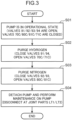
- FIG. 3 is a flowchart of the maintenance method for the pump 50.
- FIG. 4 is an enlarged schematic diagram of the liquefied hydrogen system 1S according to the present embodiment, showing a state in which a part of the flow path LS is replaced with hydrogen gas.
- FIG. 5 is a diagram showing a state in which a part of the flow path LS is further replaced with nitrogen gas.
- FIG. 6 is a diagram showing a state in which the pump 50 is separated from the flow path LS. Note that in each diagram, the valve painted white means that the valve is open, whereas the valve painted black means that the valve is closed.
- the pump 50 when the pump 50 is in an operational state, the first valve 91, the second valve 92, the third valve 93, and the fourth valve 94 are all open, whereas the hydrogen valve 70C, the nitrogen valve 80C, the nitrogen valve 81C, and the hydrogen valve 71C are all closed. In this state, the pump 50 operates to cause liquefied hydrogen to flow through the flow path LS.
- the operator closes the first valve 91 and the fourth valve 94, and opens the hydrogen valve 70C and the hydrogen valve 71C, thereby causing hydrogen gas at room temperature to flow from the hydrogen gas tank 70A into the first section LS1 of the flow path LS.
- the hydrogen gas flows into the first section LS1, the second section LS2, the third section LS3, and the fourth section LS4, whereas liquid hydrogen is discharged from the first section LS1, the second section LS2, the third section LS3, and the fourth section LS4 to the hydrogen supply and discharge unit 71. That is, the liquefied hydrogen within the first section LS1 to the fourth section LS4 is replaced with the hydrogen gas at room temperature.
- the operator closes the hydrogen valve 70C and the hydrogen valve 71C.
- the operator closes the second valve 92 and the third valve 93.
- the operator opens the nitrogen valve 80C and the nitrogen valve 81C.
- the nitrogen gas flows from the nitrogen supply unit 80 into the second section LS2 and the third section LS3, whereas the hydrogen gas is discharged from the second section LS2 and the third section LS3 to the nitrogen discharge unit 81. That is, the hydrogen gas in the second section LS2 and the third section LS3 is replaced with the nitrogen gas.
- the operator closes the nitrogen valve 80C and the nitrogen valve 81C.
- the operator separates the first joint part LT1 and the second joint part LT2 to detach the pump 50 from the flow path LS.
- the flow path LS is sealed at each joint, causing the second section LS2 and the third section LS3 to be hermetically sealed in a state filled with the nitrogen gas.
- the operator can perform maintenance on the pump 50.
- the operator reconnects the pump 50 to the flow path LS at the first joint part LT1 and the second joint part LT2. Thereafter, the operator performs the steps in the reverse order of the above detachment process. Specifically, the operator fills the pump 50, the second valve 92, and the third valve 93 with the nitrogen gas to prevent the air and the hydrogen gas from mixing. In more detail, with the second valve 92 and the third valve 93 closed, the operator opens the nitrogen valve 80C and the nitrogen valve 81C, causes the nitrogen gas to flow into the pump 50, the second section LS2, and the third section LS3, and replaces the air with the nitrogen gas.
- the operator opens the second valve 92 and the third valve 93, thereby causing the hydrogen gas to flow again into the second section LS2 and the third section LS3.
- the operator opens the first valve 91 and the fourth valve 94, thereby causing the liquefied hydrogen to flow into the first section LS1, the second section LS2, the third section LS3, and the fourth section LS4.
- the pump 50 can be operated again. Note that the opening and closing of each valve during the detachment and attachment of the pump 50 may be performed automatically.
- the first valve 91, the second valve 92, the first joint part LT1, the pump 50, the second joint part LT2, the third valve 93, and the fourth valve 94 are disposed in this order.
- the operator causes the hydrogen gas to flow into the first section LS1, the second section LS2, the third section LS3, and the fourth section LS4, discharging the liquefied hydrogen.
- the operator causes the nitrogen gas to flow into the second section LS2 and the third section LS3, discharging the hydrogen gas. Furthermore, with the nitrogen gas flowing into the second section LS2 and the third section LS3, the operator decouples and seals the flow path LS with the first joint part LT1 and the second joint part LT2, separating the pump 50.
- the pump 50 can be safely detached from the flow path LS with the pump 50 filled with the nitrogen gas.
- the melting point of nitrogen gas is -210°C, making the nitrogen gas easier to solidify when exposed to the cold energy of the liquefied hydrogen at - 253°C.
- the first section LS1 and the fourth section LS4 are filled with hydrogen gas, making it possible to prevent the cold energy of the liquefied hydrogen at approximately -253°C from being transmitted to the nitrogen gas in the second section LS2 and the third section LS3.
- the first section LS1 and the fourth section LS4 can each function as a temperature buffer.
- the pump 50 can be detached from the flow path LS for maintenance or other purposes by using the nitrogen gas, which is cheaper than helium, which is generally used as an inert gas. Therefore, maintenance of the pump 50 can be performed without being affected by the supply amount of helium gas. As a result, the maintenance cost of the liquefied hydrogen system 1S can also be reduced. After the maintenance, the operation of the pump 50 can be quickly resumed by flowing the liquefied hydrogen again into the limited area from the first valve 91 to the fourth valve 94.
- the operator when filling the hydrogen gas between the first valve 91 and the fourth valve 94 of the flow path LS, the operator closes the first valve 91 and the fourth valve 94 and introduces the hydrogen gas between the first valve 91 and the fourth valve 94, thereby discharging the liquefied hydrogen. Therefore, the hydrogen gas filling operation and the liquefied hydrogen discharge operation can be performed efficiently while the liquefied hydrogen is pushed out by the hydrogen gas.
- the operator when filling the nitrogen gas between the second valve 92 and the third valve 93 of the flow path LS, the operator closes the second valve 92 and the third valve 93 and introduces the nitrogen gas between the second valve 92 and the third valve 93, thereby discharging the hydrogen gas. In this case as well, the nitrogen gas filling operation and the hydrogen gas discharge operation can be performed efficiently while the hydrogen gas is pushed out by the nitrogen gas.
- the nitrogen supply unit 80 for supplying the nitrogen gas to the second section LS2 and the third section LS3 communicates directly with the second section LS2 of the flow path LS. Therefore, compared with the case where the nitrogen gas is supplied to the second section LS2 and the third section LS3 via the first section LS1 and the fourth section LS4, the nitrogen gas does not remain in the first section LS 1 and the fourth section LS4, preventing the remaining nitrogen gas from solidifying. With such a configuration, it is also possible to prevent the hydrogen gas from leaking from the first section LS 1 and the fourth section LS4 serving as temperature buffers into the atmosphere and to prevent air from entering the temperature buffers.
- the operator can adjust the opening and closing of the hydrogen valve 70C according to detection results of the pressure gauge 61 and the thermometer 62 to adjust the amount of hydrogen gas filled in the first section LS1.
- the operator can adjust the opening and closing of the hydrogen valve 70C according to detection results of the pressure gauge 63 and the thermometer 64 to adjust the amount of hydrogen gas filled in the fourth section LS4.
- the operator may adjust the amount of hydrogen gas filled according to the detection result of one of temperature and pressure.
- the hydrogen gas tends to contract due to the propagation of cold energy from the liquefied hydrogen, causing a drop in pressure. If the pressure in the first section LS1 is left lowered in this manner, due to the pressure difference between the first section LS1 and the second section LS2, there is a possibility that the nitrogen gas may flow into the first section LS1 through the second valve 92 and solidify within the first section LS1 due to the cold energy of the liquefied hydrogen. In the present embodiment, to prevent such problems, when the pressure in the first section LS1 drops, the operator can supply the hydrogen gas from the hydrogen supply and discharge unit 70 to keep the pressure in the first section LS1.
- the temperature of the first section LS1 drops significantly, there is a possibility that nitrogen may liquefy or solidify between the second valve 92 and the first joint part LT1. If the nitrogen gas liquefies in this way, there is a possibility that the occurrence of negative pressure may cause the hydrogen gas to leak from the first section LS1 to the second section LS2. When the hydrogen gas leaking into the second section LS2 vaporizes again due to heat input from the atmosphere, there is a possibility that this pressure may increase and the hydrogen gas may leak further into the atmosphere.
- the operator can operate the hydrogen supply and discharge unit 70 to raise the temperature of the first section LS1 by repeatedly supplying and discharging the hydrogen gas.
- the operator raises the temperature of the first section LS1.
- a small amount of hydrogen gas is discharged from the first section LS1, thereby allowing the pressure in the first section LS1 to be adjusted.
- the measurement instruments such as the pressure gauge 61 and the thermometer 62 are not essential in the present disclosure. The above adjustment operation may be performed automatically.
- the operator when filling the hydrogen gas between the first valve 91 and the fourth valve 94, the operator introduces the hydrogen gas between the first valve 91 and the second valve 92, and discharges the liquefied hydrogen from between the third valve 93 and the fourth valve 94.
- This allows the hydrogen gas to be efficiently filled between the first valve 91 and the fourth valve 94 by using the pump 50 as the flow path for the hydrogen gas.
- the operator when filling the nitrogen gas between the second valve 92 and the third valve 93, the operator introduces the nitrogen gas between the second valve 92 and the pump 50, and discharges the hydrogen gas from between the pump 50 and the third valve 93.
- This allows the nitrogen gas to be efficiently filled between the second valve 92 and the third valve 93 by using the pump 50 as the flow path for the nitrogen gas.
- the pump 50 can be filled with the nitrogen gas, allowing the pump 50 to be safely detached.
- the maintenance may take several days. Even in such a case, in the present embodiment, since the pumps 50 are disposed in parallel as shown in FIG. 1 , during maintenance of one pump, the other pump can be kept functioning, allowing the transport of liquefied hydrogen to continue. As described above, even if the pump 50 is separated from the flow path LS for an extended period of time, the operator can adjust the amount of hydrogen gas filled in the first section LS1 and the fourth section LS4, making it possible to stably suppress cold energy from being transmitted to the nitrogen gas in the second section LS2 and the third section LS3 for an extended period of maintenance.
- the equipment maintenance method according to the present disclosure has been described above, but the present disclosure is in no way limited to the above-described embodiment.
- the above-described equipment maintenance method can have the following modified embodiment.
- the valves are disposed in order along the direction in which the liquefied hydrogen flows from the liquefied hydrogen tank 100 to the hydrogen utilization facility 101.
- the direction in which the liquefied hydrogen flows may be the direction from the hydrogen utilization facility 101 to the liquefied hydrogen tank 100.
- the first valve 91, the second valve 92, the first joint part LT1, the pump 50, the second joint part LT2, the third valve 93, and the fourth valve 94 need to be disposed in order from the hydrogen utilization facility 101 to the liquefied hydrogen tank 100.
- the above embodiment has been described according to an aspect in which each of the hydrogen gas and the nitrogen gas flows through the pump 50 from the second valve 92 side to the third valve 93 side, but the present disclosure is not limited to this aspect.
- the attachment and detachment mechanism 1 may include its own supply and discharge passages for the hydrogen gas and the nitrogen gas on both sides of the pump 50.
- FIG. 7 is an enlarged schematic diagram of the liquefied hydrogen system according to a first modified embodiment of the present disclosure, showing a state in which a part of the flow path LS is filled with hydrogen gas and nitrogen gas.
- the modified embodiment which differs from the above embodiment in the supply route for the nitrogen gas to the flow path LS, will describe mainly this difference.
- the liquefied hydrogen system 1S includes a seal gas flow path 51 and a valve 52, instead of the nitrogen supply unit 80 and the nitrogen discharge unit 81 according to the above embodiment.
- the seal gas flow path 51 supplies a seal gas including nitrogen to a gap within the pump 50 to prevent leakage of the liquefied hydrogen within the pump 50.
- the operator can supply the above-described nitrogen gas to the flow path LS by switching the opening and closing of the valve 52.
- the nitrogen gas flows from the pump 50 into the flow path between the second valve 92 and the third valve 93.
- the hydrogen gas is discharged from a discharge flow path (not shown).
- the operator can separate the flow path LS at the first joint part LT1 and the second joint part LT2, and detach the pump 50.
- the pump 50 can be safely detached from the flow path LS while preventing the nitrogen gas from solidifying.
- the supply source of the nitrogen gas in the present disclosure may also be the pump 50.
- FIG. 8 is an enlarged schematic diagram of the liquefied hydrogen system according to a second modified embodiment of the present disclosure, showing a state in which a part of the flow path LS is filled with hydrogen gas and nitrogen gas.
- the above embodiment has been described according to an aspect in which the hydrogen supply and discharge unit 70 that communicates with the first section LS1 and the hydrogen supply and discharge unit 71 that communicates with the fourth section LS4 each supply and discharge the hydrogen gas via one passage.
- the supply passage and discharge passage for the hydrogen gas may be provided independently.
- the attachment and detachment mechanism 1 includes a hydrogen supply unit 75 and an adjustment hydrogen discharge unit 76.
- the hydrogen supply unit 75 has a function of supplying the hydrogen gas to the section from the first valve 91 to the fourth valve 94.
- the hydrogen supply unit 75 has a function of adjusting the amount of hydrogen gas filled in the first section LS1 by supplying the hydrogen gas to the first section LS1 after the second valve 92 is closed.
- the adjustment hydrogen discharge unit 76 has a function of adjusting the amount of hydrogen gas filled in the first section LS 1 by discharging the hydrogen gas from the first section LS1 after the second valve 92 is closed.
- the attachment and detachment mechanism 1 includes an adjustment hydrogen supply unit 85 and a hydrogen discharge unit 86.
- the hydrogen discharge unit 86 has a function of accepting the liquefied hydrogen and the hydrogen gas from the section from the first valve 91 to the fourth valve 94.
- the hydrogen discharge unit 86 has a function of adjusting the amount of hydrogen filled in the fourth section LS4 by accepting the hydrogen gas from the fourth section LS4 after the third valve 93 is closed.
- the adjustment hydrogen supply unit 85 has a function of adjusting the amount of hydrogen gas filled in the fourth section LS4 by supplying the hydrogen gas to the fourth section LS4 after the third valve 93 is closed.
- the operator can adjust the supply amount of hydrogen gas supplied from the hydrogen supply unit 75 and the discharge amount of hydrogen gas discharged from the adjustment hydrogen discharge unit 76 according to the detection results of the pressure gauge 61 and the thermometer 62.
- the operator can adjust the supply amount of hydrogen gas supplied from the adjustment hydrogen supply unit 85 and the discharge amount of hydrogen gas discharged from the hydrogen discharge unit 86 according to the detection results of the pressure gauge 63 and the thermometer 64.
- the pressure gauge 61 or the thermometer 62 detects that the pressure or temperature of the hydrogen gas has dropped, the operator preferably increases the supply amount of hydrogen gas supplied from the hydrogen supply unit 75. The same applies to the adjustment hydrogen supply unit 85.
- An equipment maintenance method is an equipment maintenance method in a flow path having a first valve, a second valve, equipment, a third valve, and a fourth valve disposed in order along a direction in which liquefied hydrogen flows, and includes: filling hydrogen gas between the first valve and the fourth valve in the flow path; filling nitrogen gas between the second valve and the third valve in the flow path from a state where the hydrogen gas is filled between the first valve and the fourth valve in the flow path; and decoupling and sealing the flow path between the second valve and the equipment and between the third valve and the equipment, and separating the equipment from the flow path with the nitrogen gas filled between the second valve and the third valve in the flow path.
- the equipment maintenance can be safely performed.
- the operation of the equipment can be quickly resumed by flowing the liquefied hydrogen again into the limited area from the first valve to the fourth valve.
- the hydrogen gas filled between the first valve and the second valve and between the third valve and the fourth valve functions as a temperature buffer, thereby preventing the cold energy of the liquefied hydrogen from being transmitted to the nitrogen gas during the equipment maintenance and the nitrogen gas from solidifying.
- the above method may further include closing the first valve and the fourth valve when filling the hydrogen gas between the first valve and the fourth valve in the flow path, and discharging the liquefied hydrogen by introducing the hydrogen gas between the first valve and the fourth valve.
- the above method may further include closing the second valve and the third valve when filling the nitrogen gas between the second valve and the third valve in the flow path, and discharging the hydrogen gas by introducing the nitrogen gas between the second valve and the third valve.
- the above method may further include introducing the hydrogen gas between the first valve and the second valve when filling the hydrogen gas between the first valve and the fourth valve in the flow path, and discharging the liquefied hydrogen from between the third valve and the fourth valve.
- the hydrogen gas can be efficiently filled between the first valve and the fourth valve by using the equipment as the flow path for the hydrogen gas.
- the above method may further include introducing the nitrogen gas between the second valve and the equipment when filling the nitrogen gas between the second valve and the third valve in the flow path, and discharging the hydrogen gas from between the equipment and the third valve.
- the nitrogen gas can be efficiently filled in the section from the second valve to the third valve by using the equipment as the flow path for the nitrogen gas.
- the interior of the equipment can be filled with the nitrogen gas, allowing the equipment to be safely detached.
- the above method may further include detecting temperature and pressure between the first valve and the second valve or between the third valve and the fourth valve with the equipment separated from the flow path, and adjusting an amount of the hydrogen gas filled according to a detection result of at least one of the temperature and the pressure.
- the above method may further include increasing the amount of hydrogen gas filled when a drop in the temperature or the pressure between the first valve and the second valve or between the third valve and the fourth valve is detected.
Landscapes
- Engineering & Computer Science (AREA)
- Mechanical Engineering (AREA)
- General Engineering & Computer Science (AREA)
- Filling Or Discharging Of Gas Storage Vessels (AREA)
Applications Claiming Priority (2)
| Application Number | Priority Date | Filing Date | Title |
|---|---|---|---|
| JP2022051696A JP7851166B2 (ja) | 2022-03-28 | 2022-03-28 | 機器のメンテナンス方法、液化水素システム |
| PCT/JP2023/011248 WO2023189948A1 (ja) | 2022-03-28 | 2023-03-22 | 機器のメンテナンス方法 |
Publications (2)
| Publication Number | Publication Date |
|---|---|
| EP4484820A1 true EP4484820A1 (de) | 2025-01-01 |
| EP4484820A4 EP4484820A4 (de) | 2025-06-25 |
Family
ID=88201339
Family Applications (1)
| Application Number | Title | Priority Date | Filing Date |
|---|---|---|---|
| EP23779960.6A Pending EP4484820A4 (de) | 2022-03-28 | 2023-03-22 | Verfahren zur wartung von ausrüstungen |
Country Status (8)
| Country | Link |
|---|---|
| US (1) | US12613006B2 (de) |
| EP (1) | EP4484820A4 (de) |
| JP (1) | JP7851166B2 (de) |
| KR (1) | KR20240161165A (de) |
| AU (1) | AU2023245547B2 (de) |
| CA (1) | CA3250828A1 (de) |
| TW (2) | TWI913145B (de) |
| WO (1) | WO2023189948A1 (de) |
Cited By (1)
| Publication number | Priority date | Publication date | Assignee | Title |
|---|---|---|---|---|
| EP4632230A4 (de) * | 2022-12-28 | 2025-10-22 | Kawasaki Heavy Ind Ltd | Gasaustauschverfahren für eine flüssigwasserstoffpumpe |
Families Citing this family (1)
| Publication number | Priority date | Publication date | Assignee | Title |
|---|---|---|---|---|
| JP2025079058A (ja) * | 2023-11-09 | 2025-05-21 | 川崎重工業株式会社 | 荷役システム、切離し方法、及び、荷役開始方法 |
Family Cites Families (10)
| Publication number | Priority date | Publication date | Assignee | Title |
|---|---|---|---|---|
| JPS5495713U (de) | 1977-12-16 | 1979-07-06 | ||
| US7287558B2 (en) * | 2003-07-03 | 2007-10-30 | Arizona Public Service Company | Hydrogen handling or dispensing system |
| JP4313123B2 (ja) * | 2003-09-09 | 2009-08-12 | 東京瓦斯株式会社 | 既設配管、既設タンク内ガスの真空パージ方法及びそのためのシステム |
| KR100868856B1 (ko) * | 2007-05-23 | 2008-11-14 | 대우조선해양 주식회사 | Lng 운반선용 lng 저장탱크의 유지보수 장치 및 방법 |
| JP5584904B2 (ja) * | 2008-03-11 | 2014-09-10 | 東洋炭素株式会社 | フッ素ガス発生装置 |
| JP5495713B2 (ja) * | 2009-10-28 | 2014-05-21 | Ihiプラント建設株式会社 | Lng受入基地タンクからのlng出荷方法及びその装置 |
| NL2013505B1 (en) * | 2014-09-19 | 2016-09-29 | Valvetight B V | A method of preparing a system for maintenance. |
| JP6418680B2 (ja) * | 2014-09-30 | 2018-11-07 | 川崎重工業株式会社 | 液化水素移送システム |
| CN216113358U (zh) * | 2021-11-22 | 2022-03-22 | 成都深冷科技有限公司 | 一种用于液氢加气站系统的液氢冷能利用装置 |
| EP4446640A3 (de) * | 2021-11-22 | 2025-01-01 | L'air Liquide, Societe Anonyme Pour L'etude Et L'exploitation Des Procedes Georges Claude | Verfahren zum betrieb einer versorgungskette für kalte kryogene flüssigkeit |
-
2022
- 2022-03-28 JP JP2022051696A patent/JP7851166B2/ja active Active
-
2023
- 2023-03-22 CA CA3250828A patent/CA3250828A1/en active Pending
- 2023-03-22 US US18/848,643 patent/US12613006B2/en active Active
- 2023-03-22 AU AU2023245547A patent/AU2023245547B2/en active Active
- 2023-03-22 EP EP23779960.6A patent/EP4484820A4/de active Pending
- 2023-03-22 KR KR1020247034080A patent/KR20240161165A/ko active Pending
- 2023-03-22 WO PCT/JP2023/011248 patent/WO2023189948A1/ja not_active Ceased
- 2023-03-24 TW TW114112351A patent/TWI913145B/zh active
- 2023-03-24 TW TW112111211A patent/TWI882302B/zh active
Cited By (1)
| Publication number | Priority date | Publication date | Assignee | Title |
|---|---|---|---|---|
| EP4632230A4 (de) * | 2022-12-28 | 2025-10-22 | Kawasaki Heavy Ind Ltd | Gasaustauschverfahren für eine flüssigwasserstoffpumpe |
Also Published As
| Publication number | Publication date |
|---|---|
| AU2023245547B2 (en) | 2026-03-05 |
| CA3250828A1 (en) | 2025-03-10 |
| TW202348543A (zh) | 2023-12-16 |
| JP2023144623A (ja) | 2023-10-11 |
| US20250207731A1 (en) | 2025-06-26 |
| AU2023245547A1 (en) | 2024-10-17 |
| TWI882302B (zh) | 2025-05-01 |
| JP7851166B2 (ja) | 2026-04-24 |
| WO2023189948A1 (ja) | 2023-10-05 |
| KR20240161165A (ko) | 2024-11-12 |
| EP4484820A4 (de) | 2025-06-25 |
| TW202532772A (zh) | 2025-08-16 |
| US12613006B2 (en) | 2026-04-28 |
| TWI913145B (zh) | 2026-01-21 |
Similar Documents
| Publication | Publication Date | Title |
|---|---|---|
| EP4484820A1 (de) | Verfahren zur wartung von ausrüstungen | |
| US6938654B2 (en) | Monitoring of ultra-high purity product storage tanks during transportation | |
| US5582366A (en) | Satellite fueling system and method therefor | |
| US6291939B1 (en) | Ion source device | |
| CN111399572B (zh) | B型液货舱附属处所的环境控制系统及方法 | |
| KR101755190B1 (ko) | 시료 채취 장치 및 시료 채취 방법 | |
| CN106715997A (zh) | 液化氢输送系统 | |
| JP2019035608A (ja) | リーク検査装置およびリーク検査装置における検査ガス回収方法 | |
| JP2021167671A (ja) | 加圧ガスタンクを充填するための装置及び方法 | |
| US12422098B2 (en) | Portable cargo handling equipment for liquid hydrogen and emergency release method | |
| CN209856762U (zh) | Lng加气站 | |
| KR20220127522A (ko) | 수소충전설비 평가장치의 폐수소 회수장치 | |
| JPS63252538A (ja) | 薬液供給装置 | |
| JP2025079058A (ja) | 荷役システム、切離し方法、及び、荷役開始方法 | |
| KR100870875B1 (ko) | 액화가스 화물창의 이차 방벽의 건전성 평가 방법 | |
| AU2017339047A1 (en) | Methods and system for filling a suppressant container | |
| CN118442530B (zh) | 加氢站用的卸气柱的控制方法、电子设备、存储介质 | |
| JP2025010813A (ja) | 真空断熱多重管の終端構造 | |
| JP2000046300A (ja) | ガス供給装置とそのガス供給方法 | |
| CN218409526U (zh) | 二氧化碳充装装置 | |
| JP2715271B2 (ja) | 液化ガス充填容器の検査方法 | |
| JPH07138092A (ja) | 分子線結晶成長装置 | |
| JP6579011B2 (ja) | タンクの気密検査方法 | |
| JP2024179080A (ja) | 液化ガスの荷役方法および荷役装置 | |
| JP2013228020A (ja) | ガスタンク検査装置、および、ガスタンク検査方法 |
Legal Events
| Date | Code | Title | Description |
|---|---|---|---|
| STAA | Information on the status of an ep patent application or granted ep patent |
Free format text: STATUS: THE INTERNATIONAL PUBLICATION HAS BEEN MADE |
|
| PUAI | Public reference made under article 153(3) epc to a published international application that has entered the european phase |
Free format text: ORIGINAL CODE: 0009012 |
|
| STAA | Information on the status of an ep patent application or granted ep patent |
Free format text: STATUS: REQUEST FOR EXAMINATION WAS MADE |
|
| 17P | Request for examination filed |
Effective date: 20240927 |
|
| AK | Designated contracting states |
Kind code of ref document: A1 Designated state(s): AL AT BE BG CH CY CZ DE DK EE ES FI FR GB GR HR HU IE IS IT LI LT LU LV MC ME MK MT NL NO PL PT RO RS SE SI SK SM TR |
|
| A4 | Supplementary search report drawn up and despatched |
Effective date: 20250527 |
|
| RIC1 | Information provided on ipc code assigned before grant |
Ipc: F17D 1/04 20060101ALI20250521BHEP Ipc: F17C 13/04 20060101ALI20250521BHEP Ipc: F17C 13/00 20060101AFI20250521BHEP |
|
| DAV | Request for validation of the european patent (deleted) | ||
| DAX | Request for extension of the european patent (deleted) | ||
| GRAP | Despatch of communication of intention to grant a patent |
Free format text: ORIGINAL CODE: EPIDOSNIGR1 |
|
| STAA | Information on the status of an ep patent application or granted ep patent |
Free format text: STATUS: GRANT OF PATENT IS INTENDED |
|
| RIC1 | Information provided on ipc code assigned before grant |
Ipc: F17C 13/00 20060101AFI20260326BHEP Ipc: F17C 13/04 20060101ALI20260326BHEP Ipc: F17D 1/04 20060101ALI20260326BHEP |