EP4484822A1 - Composant de distribution de gaz pour brûleur - Google Patents
Composant de distribution de gaz pour brûleur Download PDFInfo
- Publication number
- EP4484822A1 EP4484822A1 EP24183630.3A EP24183630A EP4484822A1 EP 4484822 A1 EP4484822 A1 EP 4484822A1 EP 24183630 A EP24183630 A EP 24183630A EP 4484822 A1 EP4484822 A1 EP 4484822A1
- Authority
- EP
- European Patent Office
- Prior art keywords
- oxidant
- fuel
- gas distribution
- supply channel
- diffusion
- Prior art date
- Legal status (The legal status is an assumption and is not a legal conclusion. Google has not performed a legal analysis and makes no representation as to the accuracy of the status listed.)
- Granted
Links
Images


Classifications
-
- F—MECHANICAL ENGINEERING; LIGHTING; HEATING; WEAPONS; BLASTING
- F23—COMBUSTION APPARATUS; COMBUSTION PROCESSES
- F23D—BURNERS
- F23D14/00—Burners for combustion of a gas, e.g. of a gas stored under pressure as a liquid
- F23D14/46—Details
-
- F—MECHANICAL ENGINEERING; LIGHTING; HEATING; WEAPONS; BLASTING
- F23—COMBUSTION APPARATUS; COMBUSTION PROCESSES
- F23D—BURNERS
- F23D14/00—Burners for combustion of a gas, e.g. of a gas stored under pressure as a liquid
- F23D14/02—Premix gas burners, i.e. in which gaseous fuel is mixed with combustion air upstream of the combustion zone
-
- F—MECHANICAL ENGINEERING; LIGHTING; HEATING; WEAPONS; BLASTING
- F23—COMBUSTION APPARATUS; COMBUSTION PROCESSES
- F23D—BURNERS
- F23D14/00—Burners for combustion of a gas, e.g. of a gas stored under pressure as a liquid
- F23D14/20—Non-premix gas burners, i.e. in which gaseous fuel is mixed with combustion air on arrival at the combustion zone
- F23D14/22—Non-premix gas burners, i.e. in which gaseous fuel is mixed with combustion air on arrival at the combustion zone with separate air and gas feed ducts, e.g. with ducts running parallel or crossing each other
-
- F—MECHANICAL ENGINEERING; LIGHTING; HEATING; WEAPONS; BLASTING
- F23—COMBUSTION APPARATUS; COMBUSTION PROCESSES
- F23C—METHODS OR APPARATUS FOR COMBUSTION USING FLUID FUEL OR SOLID FUEL SUSPENDED IN A CARRIER GAS OR AIR
- F23C6/00—Combustion apparatus characterised by the combination of two or more combustion chambers or combustion zones, e.g. for staged combustion
- F23C6/04—Combustion apparatus characterised by the combination of two or more combustion chambers or combustion zones, e.g. for staged combustion in series connection
- F23C6/045—Combustion apparatus characterised by the combination of two or more combustion chambers or combustion zones, e.g. for staged combustion in series connection with staged combustion in a single enclosure
- F23C6/047—Combustion apparatus characterised by the combination of two or more combustion chambers or combustion zones, e.g. for staged combustion in series connection with staged combustion in a single enclosure with fuel supply in stages
-
- F—MECHANICAL ENGINEERING; LIGHTING; HEATING; WEAPONS; BLASTING
- F23—COMBUSTION APPARATUS; COMBUSTION PROCESSES
- F23D—BURNERS
- F23D14/00—Burners for combustion of a gas, e.g. of a gas stored under pressure as a liquid
- F23D14/32—Burners for combustion of a gas, e.g. of a gas stored under pressure as a liquid using a mixture of gaseous fuel and pure oxygen or oxygen-enriched air
-
- F—MECHANICAL ENGINEERING; LIGHTING; HEATING; WEAPONS; BLASTING
- F23—COMBUSTION APPARATUS; COMBUSTION PROCESSES
- F23D—BURNERS
- F23D14/00—Burners for combustion of a gas, e.g. of a gas stored under pressure as a liquid
- F23D14/46—Details
- F23D14/62—Mixing devices; Mixing tubes
-
- F—MECHANICAL ENGINEERING; LIGHTING; HEATING; WEAPONS; BLASTING
- F23—COMBUSTION APPARATUS; COMBUSTION PROCESSES
- F23D—BURNERS
- F23D14/00—Burners for combustion of a gas, e.g. of a gas stored under pressure as a liquid
- F23D14/46—Details
- F23D14/70—Baffles or like flow-disturbing devices
-
- F—MECHANICAL ENGINEERING; LIGHTING; HEATING; WEAPONS; BLASTING
- F23—COMBUSTION APPARATUS; COMBUSTION PROCESSES
- F23M—CASINGS, LININGS, WALLS OR DOORS SPECIALLY ADAPTED FOR COMBUSTION CHAMBERS, e.g. FIREBRIDGES; DEVICES FOR DEFLECTING AIR, FLAMES OR COMBUSTION PRODUCTS IN COMBUSTION CHAMBERS; SAFETY ARRANGEMENTS SPECIALLY ADAPTED FOR COMBUSTION APPARATUS; DETAILS OF COMBUSTION CHAMBERS, NOT OTHERWISE PROVIDED FOR
- F23M9/00—Baffles or deflectors for air or combustion products; Flame shields
- F23M9/02—Baffles or deflectors for air or combustion products; Flame shields in air inlets
-
- F—MECHANICAL ENGINEERING; LIGHTING; HEATING; WEAPONS; BLASTING
- F23—COMBUSTION APPARATUS; COMBUSTION PROCESSES
- F23N—REGULATING OR CONTROLLING COMBUSTION
- F23N1/00—Regulating fuel supply
-
- F—MECHANICAL ENGINEERING; LIGHTING; HEATING; WEAPONS; BLASTING
- F23—COMBUSTION APPARATUS; COMBUSTION PROCESSES
- F23C—METHODS OR APPARATUS FOR COMBUSTION USING FLUID FUEL OR SOLID FUEL SUSPENDED IN A CARRIER GAS OR AIR
- F23C2201/00—Staged combustion
- F23C2201/20—Burner staging
-
- F—MECHANICAL ENGINEERING; LIGHTING; HEATING; WEAPONS; BLASTING
- F23—COMBUSTION APPARATUS; COMBUSTION PROCESSES
- F23C—METHODS OR APPARATUS FOR COMBUSTION USING FLUID FUEL OR SOLID FUEL SUSPENDED IN A CARRIER GAS OR AIR
- F23C2900/00—Special features of, or arrangements for combustion apparatus using fluid fuels or solid fuels suspended in air; Combustion processes therefor
- F23C2900/06041—Staged supply of oxidant
-
- Y—GENERAL TAGGING OF NEW TECHNOLOGICAL DEVELOPMENTS; GENERAL TAGGING OF CROSS-SECTIONAL TECHNOLOGIES SPANNING OVER SEVERAL SECTIONS OF THE IPC; TECHNICAL SUBJECTS COVERED BY FORMER USPC CROSS-REFERENCE ART COLLECTIONS [XRACs] AND DIGESTS
- Y02—TECHNOLOGIES OR APPLICATIONS FOR MITIGATION OR ADAPTATION AGAINST CLIMATE CHANGE
- Y02E—REDUCTION OF GREENHOUSE GAS [GHG] EMISSIONS, RELATED TO ENERGY GENERATION, TRANSMISSION OR DISTRIBUTION
- Y02E20/00—Combustion technologies with mitigation potential
- Y02E20/34—Indirect CO2mitigation, i.e. by acting on non CO2directly related matters of the process, e.g. pre-heating or heat recovery
Definitions
- the present application relates to a gas distribution component for a burner. Specifically, the present application relates to a gas distribution component for distributing a reactant fluid to a burner.
- oxy-fuel combustion has a lower investment cost, higher combustion efficiency, lower NOx emissions and higher product quality than conventional air combustion.
- a common staged oxy-fuel burner has at least one fuel channel and at least one oxidant channel.
- oxygen staging By means of oxygen staging, a portion of oxygen can be diverted, thereby delaying combustion.
- a nozzle end of the burner produces a substantially flat fuel-rich flame, and a staging nozzle introduces a portion of oxidant from above or below the fuel-rich flame, thus producing a fuel-lean flame.
- Chinese invention patent publication no. CN114667412A has disclosed a system for synchronized oxy-fuel boosting of a regenerative glass melting furnace; a first double-staged fuel burner of that system has a primary oxygen valve to apportion a flow of oxygen between primary oxygen and staged oxygen, and a staging mode valve to apportion the flow of staged oxygen between an upper staging port and a lower staging port.
- the staging oxygen can be directionally controlled and proportioned through either or both of the upper or lower staging ports adjacent to the primary pre-combustor via the staging mode valve.
- the present application hopes to solve the technical problems in the prior art mentioned above, by providing a gas distribution component which is easy to operate and adjust and has a low manufacturing cost, mainly for the purpose of introducing oxidant into a multi-stage burner.
- a gas distribution component for a burner comprising:
- the ratio of (a) a total effective flow cross section for the oxidant from the diffusion/buffering chamber to the oxidant delivery components to (b) a total volume of the diffusion/buffering chamber is set as a buffering ratio coefficient, which is in the range of 5% - 50% m 2 /m 3 , preferably 10% - 40% m 2 /m 3 , more preferably 15% - 35% m 2 /m 3 , and more preferably 20% - 30% m 2 /m 3 .
- the objective of setting this coefficient is to control the flow speed of oxidant, and achieve a buffering effect, to adapt to low gas intake pressure conditions.
- a baffle may be provided at a junction of the diffusion/buffering chamber and each oxidant delivery component, the baffle partially blocking an inlet of the oxidant delivery component.
- the diameters of the multiple through-holes are distributed non-uniformly.
- the multiple through-holes are configured such that middle through-holes are of smaller diameter while peripheral through-holes are of larger diameter.
- the middle through-holes are through-holes at a shorter distance from the oxidant inlet.
- the present invention also relates to a burner comprising such a gas distribution component.
- the gas distribution component/burner is provided with a fuel inlet, and the oxidant inlet is not in communication with the fuel inlet. That is to say, no structure for mixing fuel and oxidant isprovided and the corresponding burner is what is known in the art as a non-premix burner.
- the oxidant delivery components may comprise a primary oxidant fuel delivery component, a secondary oxidant delivery component and a tertiary oxidant delivery component; the secondary oxidant delivery component and the tertiary oxidant delivery component are arranged on the same side of the primary oxidant fuel delivery component, and the secondary oxidant delivery component is located between the tertiary oxidant delivery component and the primary oxidant fuel delivery component.
- the corresponding burner is therefore a multi-stage burner.
- the primary oxidant fuel delivery component may comprise:
- the secondary oxidant delivery component comprising at least one secondary oxidant supply channel for secondary oxidant to flow through, one end of the at least one secondary oxidant supply channel being provided with a secondary oxidant nozzle.
- the tertiary oxidant delivery component comprising at least one tertiary oxidant supply channel for tertiary oxidant to flow through, one end of the at least one tertiary oxidant supply channel being provided with a tertiary oxidant nozzle.
- the invention also relates to the use of the multi-stage burner according to Claim 11 for the combustion of the fuel with the oxidant, in particular in a melting operation in a furnace.
- the total oxidant is advantageously divided in the primary oxidant and the secondary and/or tertiary oxidant so that the primary oxidant accounting for more than 0% and less than 20%, preferably less than 10%, more preferably 2% - 5% of the total oxidant.
- the oxidant is oxygen
- oxidant inlet channel - 101 oxidant inlet - 102, outside wall of diffusion/buffering chamber - 103, fuel inlet channel - 104, fuel inlet - 105, oxidant supply conduit - 106, flow-guiding partition - 201, bolt - 301, primary oxidant fuel delivery component - 302, secondary oxidant delivery component - 303, tertiary oxidant delivery component - 304, through-holes - 305, diffusion/buffering chamber - 401, baffle - 501.
- orientational or positional relationships indicated by terms such as “upper”, “lower”, “left”, “right”, “vertical”, “horizontal”, “inner” and “outer” are based on the orientational or positional relationships shown in the drawings, and are merely simplified descriptions intended to facilitate description of the present application, without indicating or implying that the device or element referred to must have a specific orientation or be constructed and operated in a specific orientation, and therefore must not be construed as limiting the present application.
- the terms “first”, “second” and “third” merely serve a descriptive purpose, and must not be construed as indicating or implying relative importance.
- the expression “around” or “surrounding” essentially means that an annular shape is formed, substantially meaning that an inner ring is enclosed within an outer ring, so that a certain gap is present between an inner layer and an outer layer.
- This gap may be an annular gap or a non-annular gap.
- this may mean that a primary oxidant supply channel surrounds a portion (e.g. more than half) of the circumference of a fuel supply channel, or that the primary oxidant supply channel surrounds the entire circumference of the fuel supply channel. The latter case may be interpreted as meaning that the primary oxidant supply channel is arranged to completely surround the circumference of the fuel supply channel in the circumferential direction.
- the design of a fuel nozzle and an annular nozzle may be understood in a similar way.
- staging means causing fuel and oxidant to mix at different times and different positions, making it possible to achieve low nitrogen oxide emissions and control of a gas atmosphere near a molten material surface.
- the meaning of staging is that oxidant can be supplied at a different ratio or flow speed via another nozzle spaced apart from the fuel nozzle. For example, when the staging of secondary oxidant and tertiary oxidant is 95%, this means that the remaining 5% of the oxidant is supplied with fuel to a primary oxidant fuel delivery component.
- the expression "fuel” means gaseous, liquid or solid fuels that can be used in place of one another or used in combination.
- the gaseous fuel may be natural gas (mainly methane), propane, hydrogen or any other hydrocarbon compound and/or sulfur-containing compound.
- the solid or liquid fuel may mainly be any compound in a carbon-containing and/or hydrocarbon and/or sulfur-containing form.
- the solid fuel can be selected from petroleum coke, coal powder, biomass particles or another fossil fuel, and the solid fuel generally requires a carrier gas (such as air or carbon dioxide) to form a delivery wind for delivery.
- the liquid fuel can be selected from liquid hydrocarbons or coal tar.
- the expression "oxidant” may be composed of an oxidant such as air or oxygen-rich air.
- the oxidant is preferably composed of an oxidant with a molar oxygen concentration of at least 50%, preferably at least 80%, more preferably at least 90% and most preferably at least 95%.
- These oxidants include oxygen-rich air containing at least 50% oxygen by volume, such as 99.5% pure oxygen produced by a cryogenic air separation plant, or non-pure oxygen (88% or more by volume) produced by a vacuum pressure swing adsorption process, or oxygen produced by any other source.
- oxygen-containing fuel herein can eliminate nitrogen in a melting operation, and reduce NOx and particulate emissions to below a standard.
- the use of an oxy-fuel burner can achieve different flame momenta, melt coverage rates and flame radiation characteristics.
- the main sources of nitrogen are air leakage, low-purity oxygen supplied from a vacuum pressure swing adsorption or pressure swing adsorption apparatus, nitrogen in the fuel (e.g. natural gas), or nitrogen contained in the melting raw material packed in the heating furnace.
- the fuel supply channel, primary oxidant supply channel, secondary oxidant supply channel and tertiary oxidant supply channel may be substantially annular channels, and may have inlet and outlet regions.
- each of the substantially annular channels is preferably annular, but this shape can also be non-annular.
- Chinese invention patent application no. CN202080084376.9 has disclosed a burner for fuel combustion and a combustion method thereof, the disclosed content and entire content thereof being incorporated herein.
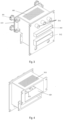
- Fig. 1 shows a 3D schematic drawing of a gas distribution component for a burner.
- Oxidant enters an oxidant inlet channel 101 via an oxidant inlet 102.
- through-holes 305 are provided on a wall of the oxidant inlet channel 101 that is adjacent to a diffusion/buffering chamber; oxidant is dispersed to the diffusion/buffering chamber 401 through these through-holes 305.
- An outside wall 103 of the diffusion/buffering chamber 401 is detachably connected to the diffusion/buffering chamber.
- bolts 301 may be used for the connection.
- the detachable connection enables an operator to clean the components of the burner quickly, thus overcoming the problem in the prior art that the components of the entire burner need to be dismantled in order to clear blockages caused by dust, etc.
- the through-holes may be distributed uniformly.
- the through-holes may be distributed such that through-holes in the middle are of small diameter while through-holes at the periphery are of large diameter. Such a distribution can increase the effective area for oxidant to flow through via the peripheral through-holes, such that the oxidant flowing out of the diffusion/buffering chamber per unit area of the entire oxidant circulation cross section is more uniform, thus ensuring that the distribution of oxidant at the oxidant delivery components is more uniform, and the flame is more stable.
- an independent buffering tank may also be set up in a burner in the prior art, it is often quite remote from the burner located downstream of the buffering tank, so the buffering/smoothing effect of the buffering tank is weakened. Moreover, due to the need to connect multiple burners downstream of the buffering tank, the buffering effect on each buffering tank is different, being affected by the positions of the burners and the pipeline layout.
- the configuration of the diffusion/buffering chamber described above can ensure a buffering effect on the oxidant flow.
- multiple flow-guiding partitions 201 are arranged in the oxidant inlet channel 101.
- the flow-guiding partitions 201 are oriented to be substantially parallel to the direction of a central axis of the oxidant inlet.
- the flow-guiding partitions 201 can guide and direct the oxidant in the oxidant inlet channel.
- the oxidant delivery components comprise a primary oxidant fuel delivery component 302, a secondary oxidant delivery component 303 and a tertiary oxidant delivery component 304.
- the secondary oxidant delivery component and the tertiary oxidant delivery component are arranged on the same side of the primary oxidant fuel delivery component, and the secondary oxidant delivery component is located between the tertiary oxidant delivery component and the primary oxidant fuel delivery component.
- the oxidant inlet is equivalent to a main inlet, delivering oxidant separately to the primary oxidant fuel delivery component 302, the secondary oxidant delivery component 303 and the tertiary oxidant delivery component 304.
- Fuel is delivered to a fuel inlet channel 104 via a fuel inlet 105, and the fuel inlet channel then conveys the fuel flow to a fuel supply channel.
- a primary oxidant supply channel for a primary oxidant flow may surround an outer wall of the fuel supply channel, and is coaxial with the fuel supply channel.
- the fuel supply channel may be a fuel conduit formed of a suitable material (e.g. high-temperature-resistant metal or ceramic). A starting end of the fuel conduit is removably connected to the entire gas distribution component, but could also be formed integrally therewith. An outlet end of the fuel conduit is connected to a fuel nozzle.
- the oxidant supply channel may be an oxidant supply conduit formed of a specific material (e.g. high-temperature-resistant metal or ceramic), but could also be a shape-fitted chamber or channel formed in a burner block.
- the secondary oxidant delivery component 303 comprises 3 oxidant supply conduits 106.
- the total oxidant can be split into three streams: a primary oxidant stream, a secondary oxidant stream and a tertiary oxidant stream.
- the primary oxidant stream surrounds the fuel nozzle, and the volume flow rate thereof accounts for only a very small proportion of the total oxidant, preferably less than 20% or less than 10% or less than 5% or about 2% - 5%.
- the remaining oxidant is used as the secondary oxidant stream and the tertiary oxidant stream. This will be respectively equivalent to a preferred staging proportion of at least 10% or at least 20% or at least 40% or at least 50% or at least 60% or even at least 70%.
- oxidant flow rates in the primary oxidant supply channel, secondary oxidant supply channel and tertiary oxidant supply channel can be independently controlled by means of an oxidant staging control mechanism.
- the primary oxidant stream it is not ideal for the primary oxidant stream to be zero; this will give rise to a void or vacuum in the primary oxidant supply channel, causing hot corrosive furnace gases to be sucked in, which will destroy the burner very quickly and cause flame instability.
- the primary oxidant stream is very small, the flame stability will also drop; and the state of mixing of gaseous fuel with oxidant will deteriorate, making it difficult to achieve a flame of practical use.
- the secondary oxidant stream or tertiary oxidant stream may be close to zero; in this case, the burner is essentially approaching or equivalent to a two-stage burner, and the corresponding combustion effect and characteristics can be predicted and adjusted according to the knowledge of those skilled in the art.
- sectional view in direction C-C shows that a baffle 501 may be provided at the junction of the diffusion/buffering chamber and each oxidant delivery component.
- the baffles can block the inlets of the oxidant delivery components as needed, thereby limiting the flow rate of oxidant conveyed to each oxidant delivery component.
- the prior art includes a variety of more precise methods of adjusting the staging proportion of the oxidant flow, e.g. by providing an oxygen staging valve, etc.
- valves have higher operation and manufacturing costs, and also take up more space in the oxidant inlet channel, so on the contrary are unsuitable for use in scenarios demanding faster and more convenient staging control.
Landscapes
- Engineering & Computer Science (AREA)
- Chemical & Material Sciences (AREA)
- Combustion & Propulsion (AREA)
- Mechanical Engineering (AREA)
- General Engineering & Computer Science (AREA)
- Pre-Mixing And Non-Premixing Gas Burner (AREA)
- Gas Burners (AREA)
- Air Supply (AREA)
Applications Claiming Priority (1)
| Application Number | Priority Date | Filing Date | Title |
|---|---|---|---|
| CN202310769771.6A CN116677996A (zh) | 2023-06-27 | 2023-06-27 | 用于燃烧器的气体分布部件 |
Publications (2)
| Publication Number | Publication Date |
|---|---|
| EP4484822A1 true EP4484822A1 (fr) | 2025-01-01 |
| EP4484822B1 EP4484822B1 (fr) | 2026-01-21 |
Family
ID=87780917
Family Applications (1)
| Application Number | Title | Priority Date | Filing Date |
|---|---|---|---|
| EP24183630.3A Active EP4484822B1 (fr) | 2023-06-27 | 2024-06-21 | Composant de distribution de gaz pour brûleur |
Country Status (6)
| Country | Link |
|---|---|
| US (1) | US20250003585A1 (fr) |
| EP (1) | EP4484822B1 (fr) |
| JP (1) | JP2025005395A (fr) |
| CN (1) | CN116677996A (fr) |
| ES (1) | ES3063835T3 (fr) |
| TW (1) | TW202500925A (fr) |
Citations (4)
| Publication number | Priority date | Publication date | Assignee | Title |
|---|---|---|---|---|
| WO2012144766A2 (fr) * | 2011-04-18 | 2012-10-26 | 주식회사 경동나비엔 | Dispositif de refroidissement de chambre à combustion et dispositif de combustion présentant une structure de refroidissement de chambre à combustion |
| EP3483521A1 (fr) * | 2016-07-11 | 2019-05-15 | Wuhu Midea Kitchen And Bath Appliances MFG. Co., Ltd | Ensemble chambre de combustion et chauffe-eau à gaz |
| EP3974743A1 (fr) * | 2019-04-25 | 2022-03-30 | Wuhu Midea Kitchen and Bath Appliances Mfg. Co., Ltd. | Boîtier pour brûleur, brûleur et appareil de chauffage d'eau |
| CN114667412A (zh) | 2019-10-25 | 2022-06-24 | 气体产品与化学公司 | 蓄热式玻璃熔炉的同步氧燃料助燃系统和方法 |
Family Cites Families (13)
| Publication number | Priority date | Publication date | Assignee | Title |
|---|---|---|---|---|
| JPS61291816A (ja) * | 1985-06-20 | 1986-12-22 | Matsushita Electric Ind Co Ltd | 触媒燃焼装置 |
| JP2716705B2 (ja) * | 1987-11-02 | 1998-02-18 | 大阪瓦斯株式会社 | ラインフレームバーナ |
| JP2573197Y2 (ja) * | 1992-05-21 | 1998-05-28 | 東京瓦斯株式会社 | 表面燃焼バーナ |
| JPH0828830A (ja) * | 1994-07-12 | 1996-02-02 | Nippon Steel Corp | 高温空気バーナ |
| US8172566B2 (en) * | 2010-02-18 | 2012-05-08 | Air Products And Chemicals, Inc. | Liquid fuel combustion process and apparatus |
| CN202216253U (zh) * | 2011-07-04 | 2012-05-09 | 上海德洲科技发展有限公司 | 可燃工业废气燃烧器 |
| CN103148483B (zh) * | 2013-02-27 | 2015-06-03 | 华中科技大学 | 一种分级混合的微小型扩散燃烧器 |
| CN105190174B (zh) * | 2013-03-15 | 2018-03-06 | 霍尼韦尔国际公司 | 具有分级氧供应的氧燃料燃烧器 |
| WO2019104614A1 (fr) * | 2017-11-30 | 2019-06-06 | 乔治洛德方法研究和开发液化空气有限公司 | Brûleur oxydant-polycombustible pouvant être utilisé pour un combustible solide et pour un combustible gazeux |
| CN210979843U (zh) * | 2019-12-02 | 2020-07-10 | 上海迎韦热能设备有限公司 | 一种用于燃烧器的气体分配装置 |
| EP4086512B1 (fr) * | 2019-12-31 | 2026-02-25 | L'air Liquide, Societe Anonyme Pour L'etude Et L'exploitation Des Procedes Georges Claude | Brûleur pour combustion de combustible et procédé de combustion associé |
| JP7030299B1 (ja) * | 2021-04-26 | 2022-03-08 | 株式会社旭製作所 | バーナヘッド装置 |
| CN219933972U (zh) * | 2023-06-27 | 2023-10-31 | 乔治洛德方法研究和开发液化空气有限公司 | 用于燃烧器的气体分布部件 |
-
2023
- 2023-06-27 CN CN202310769771.6A patent/CN116677996A/zh active Pending
-
2024
- 2024-06-04 TW TW113120599A patent/TW202500925A/zh unknown
- 2024-06-07 JP JP2024092653A patent/JP2025005395A/ja active Pending
- 2024-06-21 ES ES24183630T patent/ES3063835T3/es active Active
- 2024-06-21 EP EP24183630.3A patent/EP4484822B1/fr active Active
- 2024-06-27 US US18/757,399 patent/US20250003585A1/en active Pending
Patent Citations (4)
| Publication number | Priority date | Publication date | Assignee | Title |
|---|---|---|---|---|
| WO2012144766A2 (fr) * | 2011-04-18 | 2012-10-26 | 주식회사 경동나비엔 | Dispositif de refroidissement de chambre à combustion et dispositif de combustion présentant une structure de refroidissement de chambre à combustion |
| EP3483521A1 (fr) * | 2016-07-11 | 2019-05-15 | Wuhu Midea Kitchen And Bath Appliances MFG. Co., Ltd | Ensemble chambre de combustion et chauffe-eau à gaz |
| EP3974743A1 (fr) * | 2019-04-25 | 2022-03-30 | Wuhu Midea Kitchen and Bath Appliances Mfg. Co., Ltd. | Boîtier pour brûleur, brûleur et appareil de chauffage d'eau |
| CN114667412A (zh) | 2019-10-25 | 2022-06-24 | 气体产品与化学公司 | 蓄热式玻璃熔炉的同步氧燃料助燃系统和方法 |
Also Published As
| Publication number | Publication date |
|---|---|
| JP2025005395A (ja) | 2025-01-16 |
| EP4484822B1 (fr) | 2026-01-21 |
| US20250003585A1 (en) | 2025-01-02 |
| TW202500925A (zh) | 2025-01-01 |
| CN116677996A (zh) | 2023-09-01 |
| ES3063835T3 (en) | 2026-04-20 |
Similar Documents
| Publication | Publication Date | Title |
|---|---|---|
| EP4086512B1 (fr) | Brûleur pour combustion de combustible et procédé de combustion associé | |
| EP0877203B1 (fr) | Procédé de combustion avec oxydants doubles | |
| US9568194B2 (en) | Burner assembly and method of combustion | |
| US5431559A (en) | Oxygen-fuel burner with staged oxygen supply | |
| EP1627855B1 (fr) | Brûleur et procédé pour brûler des combustibles | |
| US7896647B2 (en) | Combustion with variable oxidant low NOx burner | |
| CN101400947B (zh) | 圆形燃烧器及其运行方法 | |
| CN109489038B (zh) | 一种可调节多种燃料进料比例的燃烧器 | |
| US20120009533A1 (en) | Multi-output valve and burner useful to promote non-stationary flame | |
| MXPA02004152A (es) | Atado de tubos venturi y quemadores y metodos que emplean dicho atado. | |
| KR20110030495A (ko) | 낮은 질소 산화물 노용 연료 분사기 | |
| CN201242149Y (zh) | 燃烧器系统 | |
| CN219933972U (zh) | 用于燃烧器的气体分布部件 | |
| EP4484822B1 (fr) | Composant de distribution de gaz pour brûleur | |
| US12429215B2 (en) | Burner with a moveable air flow diverter | |
| CN219933968U (zh) | 一种易冷却的燃烧器 | |
| CN219933969U (zh) | 一种带有点火系统的分级燃烧器 | |
| EP4565821B1 (fr) | Brûleur à modes alternés pour fonctionnement flexible | |
| RU81489U1 (ru) | Конусно-регулируемая горелка |
Legal Events
| Date | Code | Title | Description |
|---|---|---|---|
| PUAI | Public reference made under article 153(3) epc to a published international application that has entered the european phase |
Free format text: ORIGINAL CODE: 0009012 |
|
| STAA | Information on the status of an ep patent application or granted ep patent |
Free format text: STATUS: THE APPLICATION HAS BEEN PUBLISHED |
|
| AK | Designated contracting states |
Kind code of ref document: A1 Designated state(s): AL AT BE BG CH CY CZ DE DK EE ES FI FR GB GR HR HU IE IS IT LI LT LU LV MC ME MK MT NL NO PL PT RO RS SE SI SK SM TR |
|
| STAA | Information on the status of an ep patent application or granted ep patent |
Free format text: STATUS: REQUEST FOR EXAMINATION WAS MADE |
|
| 17P | Request for examination filed |
Effective date: 20250701 |
|
| GRAP | Despatch of communication of intention to grant a patent |
Free format text: ORIGINAL CODE: EPIDOSNIGR1 |
|
| STAA | Information on the status of an ep patent application or granted ep patent |
Free format text: STATUS: GRANT OF PATENT IS INTENDED |
|
| INTG | Intention to grant announced |
Effective date: 20250814 |
|
| GRAS | Grant fee paid |
Free format text: ORIGINAL CODE: EPIDOSNIGR3 |
|
| GRAA | (expected) grant |
Free format text: ORIGINAL CODE: 0009210 |
|
| STAA | Information on the status of an ep patent application or granted ep patent |
Free format text: STATUS: THE PATENT HAS BEEN GRANTED |
|
| AK | Designated contracting states |
Kind code of ref document: B1 Designated state(s): AL AT BE BG CH CY CZ DE DK EE ES FI FR GB GR HR HU IE IS IT LI LT LU LV MC ME MK MT NL NO PL PT RO RS SE SI SK SM TR |
|
| REG | Reference to a national code |
Ref country code: CH Ref legal event code: F10 Free format text: ST27 STATUS EVENT CODE: U-0-0-F10-F00 (AS PROVIDED BY THE NATIONAL OFFICE) Effective date: 20260121 |
|
| REG | Reference to a national code |
Ref country code: DE Ref legal event code: R096 Ref document number: 602024002154 Country of ref document: DE |
|
| REG | Reference to a national code |
Ref country code: NL Ref legal event code: FP |
|
| REG | Reference to a national code |
Ref country code: IE Ref legal event code: FG4D |
|
| REG | Reference to a national code |
Ref country code: ES Ref legal event code: FG2A Ref document number: 3063835 Country of ref document: ES Kind code of ref document: T3 Effective date: 20260420 |