EP4484833A1 - Adaptateur pour fixer un dispositif de commande à un agencement de soupape - Google Patents
Adaptateur pour fixer un dispositif de commande à un agencement de soupape Download PDFInfo
- Publication number
- EP4484833A1 EP4484833A1 EP23181736.2A EP23181736A EP4484833A1 EP 4484833 A1 EP4484833 A1 EP 4484833A1 EP 23181736 A EP23181736 A EP 23181736A EP 4484833 A1 EP4484833 A1 EP 4484833A1
- Authority
- EP
- European Patent Office
- Prior art keywords
- adapter
- control device
- valve
- valve arrangement
- interlocking part
- Prior art date
- Legal status (The legal status is an assumption and is not a legal conclusion. Google has not performed a legal analysis and makes no representation as to the accuracy of the status listed.)
- Granted
Links
Images




Classifications
-
- F—MECHANICAL ENGINEERING; LIGHTING; HEATING; WEAPONS; BLASTING
- F24—HEATING; RANGES; VENTILATING
- F24D—DOMESTIC- OR SPACE-HEATING SYSTEMS, e.g. CENTRAL HEATING SYSTEMS; DOMESTIC HOT-WATER SUPPLY SYSTEMS; ELEMENTS OR COMPONENTS THEREFOR
- F24D19/00—Details
- F24D19/10—Arrangement or mounting of control or safety devices
- F24D19/1006—Arrangement or mounting of control or safety devices for water heating systems
- F24D19/1009—Arrangement or mounting of control or safety devices for water heating systems for central heating
- F24D19/1015—Arrangement or mounting of control or safety devices for water heating systems for central heating using a valve or valves
- F24D19/1018—Radiator valves
-
- F—MECHANICAL ENGINEERING; LIGHTING; HEATING; WEAPONS; BLASTING
- F24—HEATING; RANGES; VENTILATING
- F24D—DOMESTIC- OR SPACE-HEATING SYSTEMS, e.g. CENTRAL HEATING SYSTEMS; DOMESTIC HOT-WATER SUPPLY SYSTEMS; ELEMENTS OR COMPONENTS THEREFOR
- F24D19/00—Details
- F24D19/10—Arrangement or mounting of control or safety devices
- F24D19/1006—Arrangement or mounting of control or safety devices for water heating systems
- F24D19/1009—Arrangement or mounting of control or safety devices for water heating systems for central heating
- F24D19/1015—Arrangement or mounting of control or safety devices for water heating systems for central heating using a valve or valves
-
- F—MECHANICAL ENGINEERING; LIGHTING; HEATING; WEAPONS; BLASTING
- F16—ENGINEERING ELEMENTS AND UNITS; GENERAL MEASURES FOR PRODUCING AND MAINTAINING EFFECTIVE FUNCTIONING OF MACHINES OR INSTALLATIONS; THERMAL INSULATION IN GENERAL
- F16B—DEVICES FOR FASTENING OR SECURING CONSTRUCTIONAL ELEMENTS OR MACHINE PARTS TOGETHER, e.g. NAILS, BOLTS, CIRCLIPS, CLAMPS, CLIPS OR WEDGES; JOINTS OR JOINTING
- F16B21/00—Means for preventing relative axial movement of a pin, spigot, shaft or the like and a member surrounding it; Stud-and-socket releasable fastenings
- F16B21/06—Releasable fastening devices with snap-action
- F16B21/07—Releasable fastening devices with snap-action in which the socket has a resilient part
- F16B21/073—Releasable fastening devices with snap-action in which the socket has a resilient part the socket having a resilient part on its inside
-
- F—MECHANICAL ENGINEERING; LIGHTING; HEATING; WEAPONS; BLASTING
- F16—ENGINEERING ELEMENTS AND UNITS; GENERAL MEASURES FOR PRODUCING AND MAINTAINING EFFECTIVE FUNCTIONING OF MACHINES OR INSTALLATIONS; THERMAL INSULATION IN GENERAL
- F16B—DEVICES FOR FASTENING OR SECURING CONSTRUCTIONAL ELEMENTS OR MACHINE PARTS TOGETHER, e.g. NAILS, BOLTS, CIRCLIPS, CLAMPS, CLIPS OR WEDGES; JOINTS OR JOINTING
- F16B7/00—Connections of rods or tubes, e.g. of non-circular section, mutually, including resilient connections
- F16B7/18—Connections of rods or tubes, e.g. of non-circular section, mutually, including resilient connections using screw-thread elements
- F16B7/182—Connections of rods or tubes, e.g. of non-circular section, mutually, including resilient connections using screw-thread elements for coaxial connections of two rods or tubes
Definitions
- the present disclosure relates to an adapter for attaching a control device to a valve arrangement, a kit comprising the adapter and the control device, a valve assembly comprising the kit and the valve arrangement, and a fluid distribution system comprising the valve assembly.
- a thermostatic radiator valve assembly provides a self-regulating control of fluid flow to a radiator.
- the thermostatic radiator valve assembly allows the temperature of a room to be controlled by changing the flow of hot water to the radiator.
- the thermostatic radiator valve assembly comprises a radiator valve arrangement and a thermostatic control device attached to radiator valve arrangement.
- the thermostatic control device may also be called a thermostatic head.
- the radiator valve arrangement is provided with a valve comprising a valve spindle that allows controlling an opening degree of the valve, where the opening degree of the valve controls the fluid flow through the valve arrangement.
- the thermostatic control device is attached to radiator valve arrangement such that the valve spindle of the valve arrangement is actuable by the thermostatic control device.
- the thermostatic control device comprises a thermal actuator configured to actuate the valve spindle in dependence of an ambient temperature around the thermostatic control device.
- the thermal actuator comprises an actuator body, an expandable material element (typically made of liquid or gas) expandable inside the actuator body in dependence of the ambient temperature, and an actuator piston connected to the valve spindle and coupled to the expandable material element such that the actuator piston moves away from the actuator body when the expandable material element expands.
- the valve will gradually close by means of the expandable material element expanding, which moves the piston, which in turn moves the valve spindle.
- the amount of hot water entering the radiator is reduced as the ambient temperature increases. This enables setting a maximum temperature for a room.
- the thermostatic control device is typically a separate part from the radiator valve arrangement. During installment of the thermostatic radiator valve assembly, the thermostatic control device is attached to radiator valve arrangement such that the valve spindle of the radiator valve arrangement is connected to and controllable (i.e. actuable) by the thermostatic control device.
- One way of way of attaching the thermostatic control device to the radiator valve arrangement is using a snap-fit connection.
- a problem with snap-fit connections is that such connections provide limited retention force, i.e., the force required to disengage the thermostatic control device from the radiator valve arrangement after the snap-fit connection has been formed.
- a limited retention force may cause unintentional disconnections of the thermostatic control device from the radiator valve arrangement.
- An unintentional disconnection may, e.g., happen if a person accidentally bumps into the thermostatic control device when it is attached to the radiator valve arrangement.
- thermostatic radiator valve assemblies Even if known thermostatic radiator valve assemblies work well for their intended use, there is room for improved ways of attaching the thermostatic control device to the radiator valve arrangement via a snap-fit connection.
- An object of the present disclosure is to provide an adapter for attaching a control device to a valve arrangement that provides an improved attachment of the control device to the valve arrangement.
- an adapter for attaching a control device to a valve arrangement such that a valve spindle of the valve arrangement is connected to and controllable by the control device.
- the adapter comprises a tubular shape extending in an axial direction. A first axial end portion of the adapter is configured to engage with the valve arrangement via a snap-fit connection, and a second axial end portion of the adapter is configured to engage with the control device via a threaded connection.
- the snap-fit connection is formed by a first interlocking part provided on an inside of the adapter engaging a second interlocking part of the valve arrangement such that the adapter is retained to the valve arrangement.
- the first interlocking part is movable in a resilient manner in a radial direction such that, when the adapter becomes engaged with the valve arrangement, the first interlocking part expands in the radial direction and thereafter snaps back in the radial direction to form the snap-fit connection.
- the adapter is provided with male threads arranged circumferentially with respect to the axial direction.
- the threaded connection is formed by the male threads engaging female threads of the control device such that the adapter is retained to the control device.
- the male threads are tapered towards the second end portion of the adapter to enable the first interlocking part to become pressed inwards in the radial direction when the adapter becomes engaged with the control device via the threaded connection and thereby preventing the first interlocking part from expanding in the radial direction when the adapter is engaged with the control device via the threaded connection.
- the adapter enables connecting a control device with a threaded interface to a valve arrangement with a snap-fit interface.
- the male threads are configured to increase a retention force of the snap-fit connection when the adapter is engaged with both the control device and the valve arrangement as compared with when the adapter is engaged with the valve arrangement but not the control device.
- the first interlocking part resists expanding in the radial direction at all times due the first interlocking part being movable in a resilient manner in the radial direction. Consequently, the snap-fit connection presents some retention force when the adapter is engaged with the valve arrangement but not the control device. By preventing the first interlocking part from expanding in the radial direction when the adapter is engaged with the control device via the threaded connection, the retention force of the snap-fit connection is increased.
- Preventing the first interlocking part from expanding in the radial direction when the adapter is engaged with the control device via the threaded connection may mean, in some embodiments, that the first interlocking part cannot expand by any amount at all. In other embodiments, preventing the first interlocking part from expanding in the radial direction when the adapter is engaged with the control device via the threaded connection may mean that the amount the interlocking part can expand (for example due to a person trying to pull the adapter from the valve arrangement) is significantly reduced (such as ten times) as compared with when the adapter is engaged with the valve arrangement but not the control device.
- the female threads preferably are straight threads or tapered less than the male threads. Since the male threads are tapered, an end portion of the female threads will exert a force radially inwards onto the male threads when engaged with the male threads. This force becomes larger the further the female threads are engaged with the male threads, i.e., how many turns the female threads has engaged with the male threads.
- the male threads are configured to at least double the retention force of the snap-fit connection when the adapter is engaged with both the control device and the valve arrangement as compared with when the adapter is engaged with the valve arrangement but not the control device.
- Retention force refers to the force required to disengage the first interlocking part from the second interlocking part after the snap-fit connection has been formed.
- the increased retention force prevents unintentional disconnections of the control device from the valve arrangement.
- the retention force is increased without increasing the mating force.
- Mating force refers to the force required to engage the first interlocking part to the second interlocking to form the snap-fit connection.
- the adapter achieves the increased retention force without separate and additional components, as compared to, e.g., an adjustable clamping ring with a screw. Consequently, manufacturing and handling of the adapter is simplified compared to other solutions requiring additional components. Furthermore, the adapter achieves the increased retention force without requiring additional actions when attaching the control device to the valve arrangement, as compared to, e.g., screwing the screw of the adjustable clamping ring. Consequently, the adapter facilitates attaching the control device to the valve arrangement.
- the control device may be a thermostatic control device.
- the control device may be other types of control devices as well, which are provided with other means of actuating the valve spindle, such as an electrical actuator or a manually rotatable handle.
- the electrical actuator, the manually rotatable handle, and other actuating means may be comprised as additional means of actuating the valve spindle in a thermostatic control device.
- the valve arrangement may be a radiator valve arrangement.
- the valve arrangement may be other types of valve arrangements as well, such as a control valve arrangement.
- the valve spindle of the valve arrangement may also be called an actuating spindle or a shaft.
- the valve arrangement may comprises a valve inlet and a valve outlet provided on a valve body.
- the valve arrangement may further comprises valve comprising a seat and closing member movable relative to the seat for enabling a variable cross section of a passage between the valve inlet and the valve outlet to be changed.
- the valve outlet is arranged downstream of the valve inlet.
- the valve arrangement is arranged to control a fluid flow between the valve inlet and the valve outlet.
- the control of fluid flow is provided by the valve, which may, e.g., be a linear valve or a rotary valve. Other types of valves are also possible.
- the valve spindle may be connected to the closing member. In that case, the position of the valve spindle relative to the valve body determines the opening size of the valve via the closing member. In other words, a position of the valve spindle relative to a valve body of the valve arrangement determines an opening size of a valve of the valve arrangement
- the closing member may move between different positions relative to the seat such that the variable cross section of the passage between the valve inlet and the valve outlet is changed. In other words, as the closing member moves closer to the seat, the amount of fluid flowing through the valve arrangement decreases. As the closing member moves away from the seat, the amount of fluid flowing through the valve arrangement increases.
- the closing member may be movable the axial direction.
- the closing member may be connected to the valve spindle.
- the valve spindle may be actuated in a linear direction along the axial direction. Furthermore, the valve spindle may extend along the axial direction.
- the closing member may have a position in which the valve is considered as fully open, i.e. providing for a largest defined opening area through the valve arrangement. Similarly, the closing member may have a position in which the valve is considered as fully closed, i.e. completely blocking fluid from flowing through the valve arrangement.
- the opening degree of the valve may be controlled in a step-less manner. However, the opening degree may be discretely controlled in steps between the fully closed position and the fully opened position.
- a tubular shape means an elongated shape like a tube. Such a shape is typically round and hollow.
- the adapter may have the shape of a cylinder.
- the adapter may have a shape of a cylinder with a slit extending from one opening to the other opening. In that case, the cylinder does not form a solid circle when looking into the cylinder from one of the openings.
- the first and the second axial end portions are portions at respective ends of the elongated shape of the adapter, e.g., at respective outmost portions of the adapter or in connection to the respective outermost portions of the adapter.
- the first axial end portion being configured to engage with the valve arrangement via a snap-fit connection and the second axial end portion being configured to engage with the control device via a threaded connection means that the adapter is configured such that the control device is attachable to one end, or in the vicinity of the one end, of the adapter, and that the valve arrangement is attachable to an opposite end, or in the vicinity of the opposite end, of the adapter.
- the first interlocking part and a second interlocking part are preferably complementary in shape.
- the first interlocking part may comprise a protrusion arranged to engage a recess forming the second interlocking part, or vice versa.
- the first interlocking part may comprise a combination of one or more protrusions and one or more recesses configured to engage a complementary shape of the second interlocking part.
- the adapter When the first interlocking part is engaged with the second interlocking part in the snap-fit connection, the adapter is retained to the valve arrangement. This means that the adapter is attached and held to the valve arrangement.
- the first interlocking part is movable in a resilient manner in the radial direction.
- the radial direction is perpendicular, or substantially perpendicular, to the axial direction.
- the adapter or at least a part of the adapter, may be made of a resilient material such that when the adapter becomes engaged with the valve arrangement, the first interlocking part expands in the radial direction and thereafter snaps back in the radial direction to form the snap-fit connection.
- the first interlocking part is resilient. Examples, of suitable materials are plastics or metal.
- the resilience of the first interlocking part may be formed at least partly mechanically, i.e., by the particular shape of the adapter.
- the first interlocking part is arranged on a protruding portion of the adapter extending in the axial direction configured to provide resilience to the first interlocking part in the radial direction.
- the adapter is provided with a slit extending between the first axial end portion of the adapter and the second end portion of the adapter to provide resilience to the first interlocking part in the radial direction.
- This slit is arranged extending all the way from one end to the other end. This slit is arranged such that it reduces the genus of the adapter by one as compared with the same adapter without the slit. For example, if the adapter without the slit is a cylinder with one through hole, the slit is arranged such that the adapter becomes a shape with zero through holes.
- the adapter may additionally, or alternatively, comprise slits not extending all the way from one end to the other of the adapter, which also provide resilience to some extent.
- the adapter is provided with male threads arranged circumferentially with respect to the axial direction.
- the male threads may extend circumferentially around an outside of that cylinder.
- the adapter When the male threads are engaged with the female threads in the threaded connection, the adapter is retained to the control device. This means that the adapter is attached and held to the control device.
- the adapter is provided with a ridge arranged circumferentially with respect to the axial direction on an outside of the adapter.
- the ridge comprises a surface arranged to abut an end of the control device when the adapter becomes engaged with the control device via the threaded connection.
- the surface is frustoconical pointing towards the first axial end portion of the adapter and is associated with an apex angle
- the ridge is arranged such that the apex angle expands when the adapter becomes engaged with the control device via the threaded connection.
- the adapter comprises a first anti-rotational part provided on the inside of the adapter configured to engage a second anti-rotational part of the valve arrangement such that the adapter is rotationally locked to the valve arrangement when the adapter is engaged with the valve arrangement via the snap-fit connection.
- the control device is rotationally locked to the adapter via the threaded connection when it is attached to the adapter.
- the first anti-rotational part makes the control device rotationally locked to the valve arrangement when the control device is attached to the valve arrangement via the adapter.
- the control device may comprise a first part and a second part, where the first part is rotationally locked to the adapter via the threaded connection when the control device is attached to the adapter, and where the second part is rotatably attached to the first part.
- a kit comprising a control device and an adapter for attaching the control device to a valve arrangement such that a valve spindle of the valve arrangement is connected to and controllable by the control device.
- the control device comprises regulating means configured to control the valve spindle when the control device is attached to the valve arrangement via the adapter.
- the adapter comprises a tubular shape extending in an axial direction.
- a first axial end portion of the adapter is configured to engage with the valve arrangement via a snap-fit connection, and a second axial end portion of the adapter is configured to engage with the control device via a threaded connection.
- the snap-fit connection is formed by a first interlocking part provided on an inside of the adapter engaging a second interlocking part of the valve arrangement such that the adapter is retained to the valve arrangement.
- the first interlocking part is movable in a resilient manner in a radial direction such that, when the adapter becomes engaged with the valve arrangement, the first interlocking part expands in the radial direction and thereafter snaps back in the radial direction to form the snap-fit connection.
- the adapter is provided with male threads arranged circumferentially with respect to the axial direction.
- the threaded connection is formed by the male threads engaging female threads of the control device such that the adapter is retained to the control device.
- the male threads and/or the female threads are tapered with respect to the axial direction.
- the male threads are configured to engage the female threads of the control device such that the first interlocking part is pressed inwards in the radial direction when the adapter becomes engaged with the control device via the threaded connection and thereby preventing the first interlocking part from expanding in the radial direction when the adapter is engaged with the control device via the threaded connection.
- one the male threads and the female threads are tapered, and the other one of the male threads and female threads are straight threads.
- the adapter of the kit is the adapter according to the first aspect of the present disclosure.
- the male threads are tapered towards the second axial end portion of the adapter.
- the female threads are preferably in that case straight threads or tapered less than the male threads. Since the male threads are tapered, an end portion of the female threads will exert a force radially inwards onto the male threads when engaged with the male threads. This force becomes larger the further the female threads are engaged with the male threads, i.e., how many turns the female threads has engaged with the male threads.
- the female threads are tapered such that an end portion of the female threads, which is the portion arranged to first engage the male threads as the control device engages the adapter, have a smaller circumference compared to an opposite end of the female threads.
- the male threads preferably are straight threads or tapered less than the female threads. Since the female threads are tapered, an end portion of the female threads will exert a force radially inwards onto the male threads when engaged with the male threads.
- the regulating means comprises a thermal actuator configured to control the valve spindle in dependence of an ambient temperature around the control device.
- the thermal actuator may comprise an actuator body, an expandable material element (typically made of liquid or gas) expandable inside the actuator body in dependence of the ambient temperature, and an actuator piston connected to the valve spindle and coupled to the expandable material element such that the actuator piston moves away from the actuator body when the expandable material element expands.
- the control device with the thermal actuator may be provided with an adjustment mechanism configured to adjust how much the expandable material element have to move the actuator piston relative to the actuator body to close the valve.
- the control device may be provided with a handle rotatable relative to the valve arrangement, where the handle is manually rotatable between different positions that set respective amounts of movement. Rotation of the handle may move the actuator body between different positions relative to the valve arrangement, which in turn changes how much the expandable material element have to move the actuator piston relative to the actuator body to close the valve.
- the kit comprises the adapter provided with the ridge.
- the control device may comprise an end arranged to abut the surface of the ridge of the adapter when the adapter becomes engaged with the control device via the threaded connection.
- valve assembly comprising the kit and the valve arrangement according to the discussions above.
- the valve assembly is associated with the above-discussed advantages.
- the valve arrangement comprises: a valve body having a valve inlet and a valve outlet; a valve spindle movable relative to the valve body; and a valve comprising a seat and closing member movable relative to the seat for enabling a variable cross section of a passage between the valve inlet and the valve outlet to be changed, wherein the closing member is connected to the valve spindle.
- a fluid distribution system comprising the valve assembly according to the discussions above.
- the fluid distribution system is associated with the above-discussed advantages.
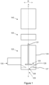
- FIG. 1 is a schematic illustration of an exploded view of a valve assembly comprising a control device 140, an adapter 100, and a valve arrangement 120.
- the valve arrangement 120 may, e.g., be a radiator valve arrangement.
- the valve arrangement 120 comprises a valve body 124 having a valve inlet 130 and a valve outlet 129, wherein the valve outlet 129 is arranged downstream of the valve inlet 130.
- the valve arrangement 120 is configured to control a fluid flow between the valve inlet 130 and the valve outlet 129 via a valve spindle 121 passing through the valve body 124.
- the valve spindle 121 may also be called a shaft.
- valve spindle 121 is movable in an axial direction A and is configured to be actuated in the axial direction A to control the fluid flow thorough the valve arrangement 120.
- a position of the valve spindle 121 relative to the valve body 124 of the valve arrangement 120 determines an opening size of a valve 125 of the valve arrangement 120.
- valve 125 which forms a linear valve.
- the valve 125 comprises a seat 127 and closing member 126 movable relative to the seat 127, wherein the closing member 126 is connected to the valve spindle 121.
- the closing member 126 is movable in the axial direction A.
- a variable cross section of a passage between the valve inlet 130 and the valve outlet 129 is changed.
- the closing member 126 moves closer to the seat 127, the amount of fluid flowing through the valve arrangement 120 decreases.
- the closing member 126 moves away from the seat 127, the amount of fluid flowing through the valve arrangement 120 increases.
- the closing member 126 has a position in which the valve 125 is considered as fully open, i.e. providing for a largest defined opening area through the valve arrangement 120. Similarly, the closing member 126 has a position in which the valve 125 is considered as fully closed, i.e. completely blocking fluid from flowing through the valve arrangement 120 (or only allowing a small leakage flow).
- the opening degree of the valve 125 may, in at least some exemplary embodiments, be controlled in a step-less manner. However, in at least some exemplary embodiments, the opening degree may be discretely controlled in steps between the fully closed position and the fully opened position.
- the control device 140 is configured to be attached to the valve arrangement 120 via the adapter 100 such that the valve spindle 121 of the valve arrangement 120 is connected to and controllable (i.e. actuable) by the control device 140.
- the adapter 100 may be attached to the valve arrangement 120 by moving the adapter 100 downwards along the axial direction A
- the control device 140 may be attached to the valve arrangement 120 via the adapter 100 by moving the control device 140 downwards along the axial direction A.
- the adapter 100 and the control device 140 together form a kit.
- the control device 140 comprises regulating means (not shown) configured to control the valve spindle 121 when the control device 140 is attached to the valve arrangement 120 via the adapter 100.
- the regulating means are configured to actuate the valve spindle 121 relative to the valve body 124 when the control device 140 is attached to the valve arrangement 120 via the adapter 100.
- the regulating means may comprise an electrically controllable actuator configured to regulate the position of the valve spindle 121.
- the regulating means may comprise movable element (such as a handle) configured to regulate the position of the valve spindle 121 in dependence of a position of the movable element relative to the valve arrangement 120.
- the regulating means comprises a thermal actuator configured to control the valve spindle 121 in dependence of an ambient temperature around the control device 140. If the regulating means comprises such a thermal actuator, the control device 140 may be called a thermostatic head.
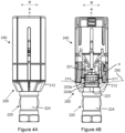
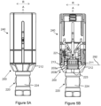
- FIGS 2A-2B , 3A-3B , 4A-4B , and 5A-5B show different views of a valve assembly comprising a control device 240, an adapter 200, and a valve arrangement 220.
- Figures 2A-2B show an exploded view of the valve assembly.
- Figure 2B shows a cut of the control device 240 and the adapter 200 from the view of Figure 2A .
- Figures 3A-3B show the valve assembly where the adapter 200 is connected to the valve arrangement 220, and where the control device 240 is about to engage the adapter 200.
- Figure 3B shows a cut of the control device 240 and the adapter 200 from the view of Figure 3A .
- Figures 4A-4B show the valve assembly where the adapter 200 is connected to the valve arrangement 220, and where the control device 240 has engaged further with the adapter 200 compared to Figures 3A-3B .
- Figure 4B shows a cut of the control device 240 and the adapter 200 from the view of Figure 4A .
- Figures 5A-4B show the valve assembly where the adapter 200 is connected to the valve arrangement 220, and where the control device 240 has fully engaged with the adapter 200.
- Figure 5B shows a cut of the control device 240 and the adapter 200 from the view of Figure 5A .
- the valve arrangement 220 is a radiator valve arrangement.
- the valve arrangement 220 comprises a valve body 224.
- the internals of the valve arrangement 220 are not shown in the figures, but the valve arrangement 220 may operate under the same principles as the valve arrangement 120 of Figure 1 .
- the valve arrangement 220 is configured to control a fluid flow through the valve arrangement via a valve spindle 221 passing through the valve body 224.
- the valve spindle 221 is movable in an axial direction A and is configured to be actuated in the axial direction A to control the fluid flow thorough the valve arrangement 220.
- a position of the valve spindle 221 relative to the valve body 224 of the valve arrangement 220 determines an opening size of a valve (not shown) of the valve arrangement 220.
- the control device 240 is configured to be attached to the valve arrangement 220 via the adapter 200 such that the valve spindle 221 of the valve arrangement 220 is connected to and controllable by the control device 240.
- the adapter 200 and the control device 240 together form a kit.
- the kit and the valve arrangement 220 together form a valve assembly.
- the control device 240 comprises regulating means configured to control the valve spindle 221 when the control device 240 is attached to the valve arrangement 220 via the adapter 200.
- the regulating means comprises a thermal actuator (not shown) configured to control the valve spindle 221 in dependence of an ambient temperature around the control device 240.
- the thermal actuator comprises an actuator body, an expandable material element (typically made of liquid or gas) expandable inside the actuator body in dependence of the ambient temperature, and an actuator piston connected to the valve spindle 221 (when the control device 240 is attached to the valve arrangement 220 via the adapter 200) and coupled to the expandable material element such that the actuator piston moves away from the actuator body when the expandable material element expands.
- an expandable material element typically made of liquid or gas
- the adapter 200 has a tubular shape extending in the axial direction A.
- a first axial end portion 201 of the adapter 200 is configured to engage with the valve arrangement 220 via a snap-fit connection.
- the first axial end portion 201 may be called a forward end portion.
- a second axial end portion 210 of the adapter 200 is at an opposite side of the adapter 200 with respect to the axial direction A.
- the second axial end portion 210 may be called a rearward end portion.
- a direction from the rearward end portion to the forward end portion along the axial direction A is called a forward direction
- a direction from the forward end portion to the rearward end portion along the axial direction A is called a rearward direction.
- the adapter 200 is configured to be attached to the valve arrangement 220 by moving the forward end portion (relative to the valve arrangement 220) in the forward direction onto the valve arrangement 220.
- the snap-fit connection is formed by a first interlocking part 203a, 203b provided on an inside 202 of the adapter 200 engaging a second interlocking part 222a, 222b of the valve arrangement 220 such that the adapter 200 is retained to the valve arrangement 220.
- the first interlocking part 203a, 203b is movable in a resilient manner in a radial direction R such that, when the adapter 200 becomes engaged with the valve arrangement 220, the first interlocking part 203a, 203b expands in the radial direction R and thereafter snaps back in the radial direction R to form the snap-fit connection.
- the second interlocking part comprises an annular protrusion 222a arranged circumferentially on the valve body 224 and arranged extending outwards in the radial direction R.
- annular protrusion 222a of the valve arrangement 220 below the annular protrusion 222a of the valve arrangement 220 ("below” means in the forward direction relative to the annular protrusion 222a), an annular grove 222b is formed circumferentially on the valve body 224, which is also comprised in the second interlocking part.
- the first interlocking part comprises a section of an annular protrusion 203a arranged circumferentially on the inside 202 of the adapter 200 and arranged extending inwards in the radial direction R.
- the first interlocking part further comprises a section of an annular grove 203b formed circumferentially on the inside 202 of the adapter 200 arranged above the section of the annular protrusion 203a of the adapter 200.
- “above” means in the rearward direction relative to the section of the annular protrusion 203a.
- the section of the annular protrusion 203b of the adapter 200 is snap-fitted into the annular grove 222b of the valve arrangement 220 and the section of the annular grove 203a of the adapter 200 is snap-fitted onto the annular protrusion 222a of the valve arrangement 220 when the adapter 200 is engaged with the valve arrangement 220 via the snap-fit connection.
- the first interlocking part 203a, 203b is discussed in more detail below in connection to Figures 6A-6D .
- a second axial end portion 210 of the adapter 200 is configured to engage with the control device 240 via a threaded connection.
- the adapter 200 is configured to be attached to the control device 240 by moving the reward end portion (relative to the control device 240) in the forward direction onto the control device 240.
- the adapter 200 is provided with male threads 211 arranged circumferentially with respect to the axial direction A.
- the threaded connection is formed by the male threads 211 engaging female threads 241 of the control device 240 such that the adapter 200 is retained to the control device 240.
- the male threads 211 are tapered towards the second end portion 210 of the adapter 200 to enable the first interlocking part 203a, 203b to become pressed inwards in the radial direction R when the adapter 200 becomes engaged with the control device 240 via the threaded connection and thereby preventing the first interlocking part 203a, 203b from expanding in the radial direction R when the adapter 200 is engaged with the control device 240 via the threaded connection.
- the male threads 211 are tapered towards the second end portion 210 of the adapter 200.
- the male threads taper in the rearward direction.
- the tapering is illustrated by dashed lines 291 in Figure 2A . Due to the tapering, the circumference at a bottommost portion of the male threads 211 in the figure is larger than the circumference at an uppermost portion of the male threads 211 in the figure.
- the female threads 241 of the control device 240 are arranged on an inside of the control device 240 in connection to an end 242 of the control device 240. It can further be seen that the female threads 241 are straight threads. Since the male threads 211 are tapered, an end portion of the female threads 241 will exert a force radially inwards onto the male threads 211 when engaged with the male threads 211. This force becomes larger the further the female threads 241 are engaged with the male threads 211, i.e., how many turns the female threads 241 has engaged with the male threads 211.
- the retention force of the snap-fit connection is increased when the adapter 200 is engaged with both the control device 240 and the valve arrangement 220 as compared with when the adapter 200 is engaged with the valve arrangement 220 but not the control device 240.
- the adapter 200 is provided with a ridge 212 arranged circumferentially with respect to the axial direction A on an outside of the adapter 200.
- the ridge 212 comprises a surface 213 arranged to abut an end 242 of the control device 240 when the adapter 200 becomes engaged with the control device 240 via the threaded connection.
- the ridge 212 is arranged at a bottom end of the male threads 211 and the end 242 of the control device 240 is arranged at a bottom end of the female threads 241.
- the male threads 211 are arranged extending from an upmost end of the adapter 200 and extend all the way to the ridge 212. Other locations of the ridge 212 relative to the male threads 211 are also possible.
- the surface 213 of the ridge 212 is frustoconical pointing towards the first axial end portion 201 of the adapter 200 and is associated with an apex angle ⁇ .
- the surface 213 of the ridge 212 is frustoconical pointing in the forward direction.
- the apex angle ⁇ is illustrated via dashed lines 292 in Figures 3B and 4B .
- the adapter 200 is connected to the valve arrangement 220, and the control device 240 is about to engage the adapter 200.
- the apex angle ⁇ remains unchanged compared to when the control device 240 is not in contact with the adapter 200.
- the ridge 212 is arranged such that the apex angle ⁇ expands when the adapter 200 becomes engaged with the control device 240 via the threaded connection.
- the control device 240 has engaged further with the adapter 200 compared to Figure 3B , and the apex angle ⁇ remains substantially the same as in Figure 3B .
- the control device 240 has fully engaged with the adapter 200, and the apex angle has expanded to close to 180 degrees.
- the tapering of the male threads 211 is reduced (i.e. the male threads 211 become closer to straight threads) as the control device 240 becomes more and more engaged with the adapter 200 when the adapter 200 is engaged with the valve arrangement 220.
- Figures 6A-6D show different views of the adapter 200 of Figures 2A-5B .
- the adapter 200 is provided with a slit 602 extending between the first axial end portion 201 of the adapter 200 and the second end portion 210 of the adapter 200 to provide resilience to the first interlocking part 203a, 203b in the radial direction R.
- This slit 602 is arranged extending all the way from one end to the other end of the adapter 200.
- This slit 602 is arranged such that it reduces the genus of the adapter 200 by one as compared with the same adapter without the slit 602.
- the adapter 200 has a shape with zero through holes.
- the arrangement of the slit 602 provides resilience of the whole adapter 200, i.e., the whole adapter 200 can compress and expand radially in a resilient manner. Consequently, resilience is also provided to the first interlocking part 203a, 203b in the radial direction R.
- Figures 6A-6D further show that the adapter 200 comprises four respective first interlocking parts 203.
- Each first interlocking part 203a, 203b is arranged on a protruding portion 204 of the adapter 200 extending in the axial direction A.
- the protruding portion 204 is configured to provide resilience to the first interlocking part 203a, 203b in the radial direction R.
- the male threads 211 are formed on the second axial end portion 210 (top part in Figure 6A ) of the adapter 200 forming a C-shape together with the slit 602.
- the four protruding portions 204 extend in the forward direction from the end part.
- the four protruding portions 204 form openings 601 between each adjacent protruding portion 204.
- One of the protruding portions 204 is divided into two parts by the slit 602.
- the adapter 200 comprises a first anti-rotational part 205 provided on the inside 202 of the adapter 200 configured to engage a second anti-rotational part 223 of the valve arrangement 220 such that the adapter 200 is rotationally locked to the valve arrangement 220 when the adapter 200 is engaged with the valve arrangement 220 via the snap-fit connection.
- the adapter 200 comprises four respective first anti-rotational parts 205 in the form of part-cylindrical protrusions arranged on respective protruding portion 204.
- the second anti-rotational part 223 can be seen in Figure 2A , for example.
- the valve arrangement 220 comprises four respective second anti-rotational parts 223 arranged circumferentially on the valve body 224. Each second anti-rotational part 223 has a complementary shape to the first anti-rotational part 205, which in this case is a part-cylindrical recess.
- FIG. 7 shows a schematic illustration of an example fluid distribution system 400.
- the valve assembly comprises a control device 140, 240, an adapter 100, 200, and a valve arrangement 120, 220.
- the fluid distribution system 400 of Figure 7 comprises a fluid source 410, such as a liquid tank, and fluid consumption point 420, such as a radiator. Relative to the valve assembly, upstream 411 is between the fluid source 410 and the valve assembly and downstream 421 is between the valve assembly and the consumption point 420. Fluid is recirculated from the fluid consumption point 420 to the fluid source 410 via a return path 422.
Landscapes
- Engineering & Computer Science (AREA)
- Physics & Mathematics (AREA)
- Thermal Sciences (AREA)
- Chemical & Material Sciences (AREA)
- Combustion & Propulsion (AREA)
- Mechanical Engineering (AREA)
- General Engineering & Computer Science (AREA)
- Lift Valve (AREA)
Priority Applications (2)
| Application Number | Priority Date | Filing Date | Title |
|---|---|---|---|
| DK23181736.2T DK4484833T3 (da) | 2023-06-27 | 2023-06-27 | Adapter til fastgørelse af en styringsanordning til en ventilanordning |
| EP23181736.2A EP4484833B1 (fr) | 2023-06-27 | 2023-06-27 | Adaptateur pour fixer un dispositif de commande à un agencement de soupape |
Applications Claiming Priority (1)
| Application Number | Priority Date | Filing Date | Title |
|---|---|---|---|
| EP23181736.2A EP4484833B1 (fr) | 2023-06-27 | 2023-06-27 | Adaptateur pour fixer un dispositif de commande à un agencement de soupape |
Publications (2)
| Publication Number | Publication Date |
|---|---|
| EP4484833A1 true EP4484833A1 (fr) | 2025-01-01 |
| EP4484833B1 EP4484833B1 (fr) | 2025-10-22 |
Family
ID=87003081
Family Applications (1)
| Application Number | Title | Priority Date | Filing Date |
|---|---|---|---|
| EP23181736.2A Active EP4484833B1 (fr) | 2023-06-27 | 2023-06-27 | Adaptateur pour fixer un dispositif de commande à un agencement de soupape |
Country Status (2)
| Country | Link |
|---|---|
| EP (1) | EP4484833B1 (fr) |
| DK (1) | DK4484833T3 (fr) |
Citations (6)
| Publication number | Priority date | Publication date | Assignee | Title |
|---|---|---|---|---|
| EP0504582B1 (fr) * | 1991-03-19 | 1997-09-10 | GIACOMINI S.p.A. | Tête thermostatique pour la vanne de commande d'un radiateur |
| EP0903544B1 (fr) * | 1997-09-18 | 2002-11-27 | Danfoss A/S | Coupelle de montage pour soupape |
| DE202004008798U1 (de) * | 2004-06-03 | 2004-09-23 | Theodor Heimeier Metallwerk Gmbh & Co. Kg | Fußteil eines Thermostatkopfes |
| EP1667006A1 (fr) * | 2004-12-03 | 2006-06-07 | Excel Distribution Limited | Capuchon d'un soupape de radiateur |
| EP1388715B1 (fr) * | 2002-08-08 | 2007-03-21 | Oliveira & Irmao S.A. | Dispositif pour connecter une tête de commande à une vanne thermostatique, notamment pour un radiateur ou pour d'autres appareils de conditionnement d'air ou d'appareils de chauffage |
| GB2570928A (en) * | 2018-02-12 | 2019-08-14 | App Wholesale Plc | Thermostatic radiator valve |
-
2023
- 2023-06-27 DK DK23181736.2T patent/DK4484833T3/da active
- 2023-06-27 EP EP23181736.2A patent/EP4484833B1/fr active Active
Patent Citations (6)
| Publication number | Priority date | Publication date | Assignee | Title |
|---|---|---|---|---|
| EP0504582B1 (fr) * | 1991-03-19 | 1997-09-10 | GIACOMINI S.p.A. | Tête thermostatique pour la vanne de commande d'un radiateur |
| EP0903544B1 (fr) * | 1997-09-18 | 2002-11-27 | Danfoss A/S | Coupelle de montage pour soupape |
| EP1388715B1 (fr) * | 2002-08-08 | 2007-03-21 | Oliveira & Irmao S.A. | Dispositif pour connecter une tête de commande à une vanne thermostatique, notamment pour un radiateur ou pour d'autres appareils de conditionnement d'air ou d'appareils de chauffage |
| DE202004008798U1 (de) * | 2004-06-03 | 2004-09-23 | Theodor Heimeier Metallwerk Gmbh & Co. Kg | Fußteil eines Thermostatkopfes |
| EP1667006A1 (fr) * | 2004-12-03 | 2006-06-07 | Excel Distribution Limited | Capuchon d'un soupape de radiateur |
| GB2570928A (en) * | 2018-02-12 | 2019-08-14 | App Wholesale Plc | Thermostatic radiator valve |
Also Published As
| Publication number | Publication date |
|---|---|
| EP4484833B1 (fr) | 2025-10-22 |
| DK4484833T3 (da) | 2025-12-15 |
Similar Documents
| Publication | Publication Date | Title |
|---|---|---|
| US11867304B2 (en) | Valve assemblies, valve seats including flexible arms, and related methods | |
| US7240850B2 (en) | Thermostatic mixing valve | |
| US9410536B2 (en) | Self-contained thermally actuated flow-control assembly | |
| EP4484833A1 (fr) | Adaptateur pour fixer un dispositif de commande à un agencement de soupape | |
| US8371553B2 (en) | Long-stroke regulator valve with a stop function | |
| EP4484832B1 (fr) | Kit comprenant un dispositif de commande et un adaptateur pour fixer le dispositif de commande à un agencement de soupape | |
| US5878766A (en) | Pressure compensated flow control valve | |
| US6926249B2 (en) | Precision modulating globe valve | |
| CN110686122B (zh) | 旋转轴向截止阀 | |
| JP2012532301A (ja) | バックラッシュ防止装置を有するモジュレータバルブアセンブリ | |
| CN111247498B (zh) | 用于混合阀的阀芯 | |
| CN110425297A (zh) | 一种高可调比旋塞调节阀 | |
| WO1987004277A1 (fr) | Soupape ajustable de regulation d'un ecoulement | |
| WO2017072108A1 (fr) | Vanne de réglage | |
| EP3334963A1 (fr) | Soupapes à disque permettant de fournir une caractéristique d'écoulement fluidique à pourcentage égal | |
| CA3050773C (fr) | Valve d'arret de securite mecanique | |
| EP1005670B1 (fr) | Soupape regulatrice de debit a pression egalisee | |
| WO2022122544A1 (fr) | Vanne à troies voies | |
| GB2392223A (en) | Improvements in or relating to thermostatic mixing valves | |
| DK202170653A1 (en) | Control valve | |
| DK202170651A1 (en) | Control valve | |
| GB2392224A (en) | Improvements in or relating to thermostatic mixing valves |
Legal Events
| Date | Code | Title | Description |
|---|---|---|---|
| PUAI | Public reference made under article 153(3) epc to a published international application that has entered the european phase |
Free format text: ORIGINAL CODE: 0009012 |
|
| STAA | Information on the status of an ep patent application or granted ep patent |
Free format text: STATUS: THE APPLICATION HAS BEEN PUBLISHED |
|
| AK | Designated contracting states |
Kind code of ref document: A1 Designated state(s): AL AT BE BG CH CY CZ DE DK EE ES FI FR GB GR HR HU IE IS IT LI LT LU LV MC ME MK MT NL NO PL PT RO RS SE SI SK SM TR |
|
| STAA | Information on the status of an ep patent application or granted ep patent |
Free format text: STATUS: REQUEST FOR EXAMINATION WAS MADE |
|
| 17P | Request for examination filed |
Effective date: 20250307 |
|
| GRAP | Despatch of communication of intention to grant a patent |
Free format text: ORIGINAL CODE: EPIDOSNIGR1 |
|
| STAA | Information on the status of an ep patent application or granted ep patent |
Free format text: STATUS: GRANT OF PATENT IS INTENDED |
|
| INTG | Intention to grant announced |
Effective date: 20250513 |
|
| RIC1 | Information provided on ipc code assigned before grant |
Ipc: F16B 21/07 20060101ALI20250502BHEP Ipc: F16B 7/18 20060101ALI20250502BHEP Ipc: G05D 23/02 20060101ALI20250502BHEP Ipc: F16B 41/00 20060101ALI20250502BHEP Ipc: F24D 19/10 20060101AFI20250502BHEP |
|
| GRAS | Grant fee paid |
Free format text: ORIGINAL CODE: EPIDOSNIGR3 |
|
| GRAA | (expected) grant |
Free format text: ORIGINAL CODE: 0009210 |
|
| STAA | Information on the status of an ep patent application or granted ep patent |
Free format text: STATUS: THE PATENT HAS BEEN GRANTED |
|
| AK | Designated contracting states |
Kind code of ref document: B1 Designated state(s): AL AT BE BG CH CY CZ DE DK EE ES FI FR GB GR HR HU IE IS IT LI LT LU LV MC ME MK MT NL NO PL PT RO RS SE SI SK SM TR |
|
| P01 | Opt-out of the competence of the unified patent court (upc) registered |
Free format text: CASE NUMBER: UPC_APP_7330_4484833/2025 Effective date: 20250917 |
|
| REG | Reference to a national code |
Ref country code: CH Ref legal event code: F10 Free format text: ST27 STATUS EVENT CODE: U-0-0-F10-F00 (AS PROVIDED BY THE NATIONAL OFFICE) Effective date: 20251022 Ref country code: GB Ref legal event code: FG4D |
|
| REG | Reference to a national code |
Ref country code: DE Ref legal event code: R096 Ref document number: 602023007698 Country of ref document: DE |
|
| REG | Reference to a national code |
Ref country code: IE Ref legal event code: FG4D |
|
| REG | Reference to a national code |
Ref country code: DK Ref legal event code: T3 Effective date: 20251210 |
|
| REG | Reference to a national code |
Ref country code: NL Ref legal event code: FP |
|
| PG25 | Lapsed in a contracting state [announced via postgrant information from national office to epo] |
Ref country code: ES Free format text: LAPSE BECAUSE OF FAILURE TO SUBMIT A TRANSLATION OF THE DESCRIPTION OR TO PAY THE FEE WITHIN THE PRESCRIBED TIME-LIMIT Effective date: 20251022 |
|
| REG | Reference to a national code |
Ref country code: LT Ref legal event code: MG9D |
|
| PG25 | Lapsed in a contracting state [announced via postgrant information from national office to epo] |
Ref country code: NO Free format text: LAPSE BECAUSE OF FAILURE TO SUBMIT A TRANSLATION OF THE DESCRIPTION OR TO PAY THE FEE WITHIN THE PRESCRIBED TIME-LIMIT Effective date: 20260122 |
|
| PG25 | Lapsed in a contracting state [announced via postgrant information from national office to epo] |
Ref country code: HR Free format text: LAPSE BECAUSE OF FAILURE TO SUBMIT A TRANSLATION OF THE DESCRIPTION OR TO PAY THE FEE WITHIN THE PRESCRIBED TIME-LIMIT Effective date: 20251022 Ref country code: FI Free format text: LAPSE BECAUSE OF FAILURE TO SUBMIT A TRANSLATION OF THE DESCRIPTION OR TO PAY THE FEE WITHIN THE PRESCRIBED TIME-LIMIT Effective date: 20251022 |
|
| PG25 | Lapsed in a contracting state [announced via postgrant information from national office to epo] |
Ref country code: RS Free format text: LAPSE BECAUSE OF FAILURE TO SUBMIT A TRANSLATION OF THE DESCRIPTION OR TO PAY THE FEE WITHIN THE PRESCRIBED TIME-LIMIT Effective date: 20260122 |
|
| PG25 | Lapsed in a contracting state [announced via postgrant information from national office to epo] |
Ref country code: IS Free format text: LAPSE BECAUSE OF FAILURE TO SUBMIT A TRANSLATION OF THE DESCRIPTION OR TO PAY THE FEE WITHIN THE PRESCRIBED TIME-LIMIT Effective date: 20260222 |
|
| PG25 | Lapsed in a contracting state [announced via postgrant information from national office to epo] |
Ref country code: PT Free format text: LAPSE BECAUSE OF FAILURE TO SUBMIT A TRANSLATION OF THE DESCRIPTION OR TO PAY THE FEE WITHIN THE PRESCRIBED TIME-LIMIT Effective date: 20260223 |
|
| PG25 | Lapsed in a contracting state [announced via postgrant information from national office to epo] |
Ref country code: PL Free format text: LAPSE BECAUSE OF FAILURE TO SUBMIT A TRANSLATION OF THE DESCRIPTION OR TO PAY THE FEE WITHIN THE PRESCRIBED TIME-LIMIT Effective date: 20251022 |
|
| PG25 | Lapsed in a contracting state [announced via postgrant information from national office to epo] |
Ref country code: LV Free format text: LAPSE BECAUSE OF FAILURE TO SUBMIT A TRANSLATION OF THE DESCRIPTION OR TO PAY THE FEE WITHIN THE PRESCRIBED TIME-LIMIT Effective date: 20251022 |