EP4484847A1 - Chauffe-eau - Google Patents
Chauffe-eau Download PDFInfo
- Publication number
- EP4484847A1 EP4484847A1 EP23182123.2A EP23182123A EP4484847A1 EP 4484847 A1 EP4484847 A1 EP 4484847A1 EP 23182123 A EP23182123 A EP 23182123A EP 4484847 A1 EP4484847 A1 EP 4484847A1
- Authority
- EP
- European Patent Office
- Prior art keywords
- casing
- housing
- flow heater
- heater according
- inlet
- Prior art date
- Legal status (The legal status is an assumption and is not a legal conclusion. Google has not performed a legal analysis and makes no representation as to the accuracy of the status listed.)
- Pending
Links
Images

Classifications
-
- F—MECHANICAL ENGINEERING; LIGHTING; HEATING; WEAPONS; BLASTING
- F24—HEATING; RANGES; VENTILATING
- F24H—FLUID HEATERS, e.g. WATER OR AIR HEATERS, HAVING HEAT-GENERATING MEANS, e.g. HEAT PUMPS, IN GENERAL
- F24H1/00—Water heaters, e.g. boilers, continuous-flow heaters or water-storage heaters
- F24H1/10—Continuous-flow heaters, i.e. heaters in which heat is generated only while the water is flowing, e.g. with direct contact of the water with the heating medium
- F24H1/101—Continuous-flow heaters, i.e. heaters in which heat is generated only while the water is flowing, e.g. with direct contact of the water with the heating medium using electric energy supply
- F24H1/102—Continuous-flow heaters, i.e. heaters in which heat is generated only while the water is flowing, e.g. with direct contact of the water with the heating medium using electric energy supply with resistance
-
- F—MECHANICAL ENGINEERING; LIGHTING; HEATING; WEAPONS; BLASTING
- F24—HEATING; RANGES; VENTILATING
- F24H—FLUID HEATERS, e.g. WATER OR AIR HEATERS, HAVING HEAT-GENERATING MEANS, e.g. HEAT PUMPS, IN GENERAL
- F24H1/00—Water heaters, e.g. boilers, continuous-flow heaters or water-storage heaters
- F24H1/10—Continuous-flow heaters, i.e. heaters in which heat is generated only while the water is flowing, e.g. with direct contact of the water with the heating medium
- F24H1/12—Continuous-flow heaters, i.e. heaters in which heat is generated only while the water is flowing, e.g. with direct contact of the water with the heating medium in which the water is kept separate from the heating medium
- F24H1/121—Continuous-flow heaters, i.e. heaters in which heat is generated only while the water is flowing, e.g. with direct contact of the water with the heating medium in which the water is kept separate from the heating medium using electric energy supply
-
- F—MECHANICAL ENGINEERING; LIGHTING; HEATING; WEAPONS; BLASTING
- F24—HEATING; RANGES; VENTILATING
- F24H—FLUID HEATERS, e.g. WATER OR AIR HEATERS, HAVING HEAT-GENERATING MEANS, e.g. HEAT PUMPS, IN GENERAL
- F24H9/00—Details
- F24H9/0005—Details for water heaters
- F24H9/001—Guiding means
- F24H9/0015—Guiding means in water channels
-
- F—MECHANICAL ENGINEERING; LIGHTING; HEATING; WEAPONS; BLASTING
- F24—HEATING; RANGES; VENTILATING
- F24H—FLUID HEATERS, e.g. WATER OR AIR HEATERS, HAVING HEAT-GENERATING MEANS, e.g. HEAT PUMPS, IN GENERAL
- F24H9/00—Details
- F24H9/02—Casings; Cover lids; Ornamental panels
-
- F—MECHANICAL ENGINEERING; LIGHTING; HEATING; WEAPONS; BLASTING
- F24—HEATING; RANGES; VENTILATING
- F24H—FLUID HEATERS, e.g. WATER OR AIR HEATERS, HAVING HEAT-GENERATING MEANS, e.g. HEAT PUMPS, IN GENERAL
- F24H9/00—Details
- F24H9/20—Arrangement or mounting of control or safety devices
- F24H9/2007—Arrangement or mounting of control or safety devices for water heaters
- F24H9/2014—Arrangement or mounting of control or safety devices for water heaters using electrical energy supply
- F24H9/2028—Continuous-flow heaters
-
- H—ELECTRICITY
- H05—ELECTRIC TECHNIQUES NOT OTHERWISE PROVIDED FOR
- H05B—ELECTRIC HEATING; ELECTRIC LIGHT SOURCES NOT OTHERWISE PROVIDED FOR; CIRCUIT ARRANGEMENTS FOR ELECTRIC LIGHT SOURCES, IN GENERAL
- H05B3/00—Ohmic-resistance heating
- H05B3/10—Heating elements characterised by the composition or nature of the materials or by the arrangement of the conductor
- H05B3/12—Heating elements characterised by the composition or nature of the materials or by the arrangement of the conductor characterised by the composition or nature of the conductive material
- H05B3/14—Heating elements characterised by the composition or nature of the materials or by the arrangement of the conductor characterised by the composition or nature of the conductive material the material being non-metallic
- H05B3/141—Conductive ceramics, e.g. metal oxides, metal carbides, barium titanate, ferrites, zirconia, vitrous compounds
-
- H—ELECTRICITY
- H05—ELECTRIC TECHNIQUES NOT OTHERWISE PROVIDED FOR
- H05B—ELECTRIC HEATING; ELECTRIC LIGHT SOURCES NOT OTHERWISE PROVIDED FOR; CIRCUIT ARRANGEMENTS FOR ELECTRIC LIGHT SOURCES, IN GENERAL
- H05B3/00—Ohmic-resistance heating
- H05B3/10—Heating elements characterised by the composition or nature of the materials or by the arrangement of the conductor
- H05B3/18—Heating elements characterised by the composition or nature of the materials or by the arrangement of the conductor the conductor being embedded in an insulating material
-
- H—ELECTRICITY
- H05—ELECTRIC TECHNIQUES NOT OTHERWISE PROVIDED FOR
- H05B—ELECTRIC HEATING; ELECTRIC LIGHT SOURCES NOT OTHERWISE PROVIDED FOR; CIRCUIT ARRANGEMENTS FOR ELECTRIC LIGHT SOURCES, IN GENERAL
- H05B3/00—Ohmic-resistance heating
- H05B3/20—Heating elements having extended surface area substantially in a two-dimensional [2D] plane, e.g. plate-heater
- H05B3/22—Heating elements having extended surface area substantially in a two-dimensional [2D] plane, e.g. plate-heater non-flexible
- H05B3/28—Heating elements having extended surface area substantially in a two-dimensional [2D] plane, e.g. plate-heater non-flexible heating conductor embedded in insulating material
-
- H—ELECTRICITY
- H05—ELECTRIC TECHNIQUES NOT OTHERWISE PROVIDED FOR
- H05B—ELECTRIC HEATING; ELECTRIC LIGHT SOURCES NOT OTHERWISE PROVIDED FOR; CIRCUIT ARRANGEMENTS FOR ELECTRIC LIGHT SOURCES, IN GENERAL
- H05B2203/00—Aspects relating to Ohmic resistive heating covered by group H05B3/00
- H05B2203/014—Heaters using resistive wires or cables not provided for in H05B3/54
Definitions
- the invention refers to a flow heater for heating liquids.
- a flow heater with the characteristics listed in the preamble of claim 1 is disclosed in US 8 731 386 B2 .
- a constant goal in the design of flow heaters for heating liquids is to provide a compact and cost-efficient flow heater.
- An object of the present invention is to provide a more compact, more robust and cost-efficient flow heater.
- the heating resistor is a wire embedded in insulating material inside a casing that is arranged in a housing in which a flow channel for liquid to be heated extends from an inlet to an outlet.
- the casing with a heating resistor can cost-efficiently be manufactured as a separate assembly that is then arranged in the housing of the flow heater.
- wire embedded in insulating material can withstand high operating temperatures such that liquid can be quickly heated in a compact flow heater.
- the wire used as a heating resistor may be made of a nickel-based alloy, e.g. a nickel chromium alloy, for example.
- the insulator in which the wire is embedded inside the casing may be a ceramic power, e.g. magnesium oxide.
- the casing may be provided with fins that are arranged inside the flow channel.
- heat can be more efficiently transferred to liquid inside the flow channel and the heating device can be made more compact and more robust.
- Fins may for example be brazed or welded to an outer surface of the casing. Fins can significantly reduce the surface temperature of the casing and thereby make heat transfer more efficient
- the casing is arranged inside the flow channel such that the flow channel braches into a first part and a second part that flow along opposite sides of the casing. In this way the transfer of heat from the casing to liquid can be improved. Fins may then be provided on both sides of the casing.
- the casing is strip-shaped or plate-shaped.
- the casing may be a flat cuboid or oval shape.
- Such a casing has two opposing broad or major sides that are connected by narrow, smaller sides. Fins may be provided on the broad sides.
- Such a casing may be produced cost-efficiently by folding a sheet of metal into a flat tube. Edges of the sheet that are brought together by folding of the sheet may be connected by welding. End sections of such a casing may then be closed with separate closure elements.
- the housing is strip-shaped or plate-shaped. That is the thickness of the housing is less than the width and length of the housing, e.g. not more than one fifth of the width and not more than one fifth of the length of the housing.
- a housing has two opposing broad or major sides that are connected by narrow, smaller sides.
- the inlet and the outlet may be provided in a narrow side, preferably in the same narrow side.
- the flow channel may have a first end section, which is adjacent to the inlet and arranged between a first narrow side of the housing and the casing, and a second end section, which is arranged adjacent to the outlet and arranged between a second narrow side of the housing and the casing.
- the first narrow side of the housing is opposite of the second narrow side.
- the end sections may have a width that increases towards the inlet and the outlet, respectively.
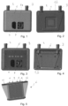
- Figures 1 and 2 show a top and bottom view, respectively, of a flow heater comprising an outer housing 1 with an inlet spigot 2 and an outlet spigot 3 as well as electrical connectors 4.
- the outer housing 1 may be a two-part housing comprising a cover part 1a and a bottom part 1b, for example.
- the flow heater may be adapted to be used in an automobile for heating liquids, for example.
- Fig. 3 shows a top view of this flow heater without the cover part.
- a circuit board 5 is visible to which electrical connectors 4 are connected.
- the circuit board is removed such that a housing 6 is visible to which the inlet spigot 2 and the outlet spigot 3 are connected and through which liquid to be heated flows.
- This housing 6 through which liquid to be heated flows is shown schematically in a semi-transparent fashion in fig. 5 .
- Fig. 6 shows an exploded view of the housing 6 shown in fig. 5 .
- a casing 8 Inside the housing 6 is a casing 8 in which a heating resistor in the form of wire is arranged.
- the wire may made of a nickel based alloy, e.g. a nickel chromium alloy.
- the wire may be wound on a molded insulator and embedded in ceramic power like magnesium oxide. Such insulator powder may fill space between heating wire and casing.
- two or more wires may be arranged as heating resistors. Terminals 9 of these wires protrude from the casing 8 and are connected to the circuit board 5 shown in fig. 3 .
- the casing 8 is plate-shaped or strip-shaped and may be a flat cuboid or oval shape, for example. It has two opposing broad or major sides that are connected by narrow, smaller sides. In fig. 6 , the casing 8 is shown in a view towards one of the broad or major sides. Both broad sides may be provided with fins 10 that may be welded or brazed to the casing 8.
- the housing 6 may also be plate-shaped and thus also have two opposing broad or major sides that are connected by narrow, smaller sides.
- the housing 6 has an inlet 11 and an outlet 12 that are connected to the inlet spigot 2 or the outlet spigot 3, respectively.
- a flow channel for liquid to be heated extends inside the housing 6 from the inlet 11 to the outlet 12.
- both the inlet 11 and the outlet 12 are arranged in the same narrow front side of the housing 8, but the inlet and/or the outlet may also be arranged at a different place.
- the flow channel inside the housing 6 has two end sections. One of these end sections is adjacent to the inlet 11, the other to the outlet 12. Between these end sections is the casing 8.
- the flow channel branches at the end section adjacent to the inlet 11 into a first part which is arranged between a first housing wall and a first surface of the casing 8, and a second part, which is arranged between a second housing wall and a second surface of the casing 8, wherein the second surface of the casing 8 is opposite to the first surface of the casing 8.
- part of the liquid to be heated flows behind the casing 8 between the casing 8 and a rear wall of the housing 6 and another part flows in front of the casing 8 between the housing's front wall shown in fig. 5 and the casing 8.
- the flow channel's end sections to the left and to the right of the casing 6 are tapering in a direction away from the inlet 11 or the out 12, respectively.
- a distance from a narrow side of the casing 8 to an adjacent inner surface of the housing 6 decreases with increasing distance from the inlet 11 or the outlet 12, respectively.
- the amount of liquid to be heated in the end section to the left of the casing 8 decreases with increasing distance from the inlet 11 as more and more liquid flows into the gap between the fin bearing broad sides of the casing 8 and the adjacent housing wall.
- the tapering end sections improve flow of liquid through the housing 6.
- Fig. 7 shows schematically a detail of a cross-section of the flow heater without the outer housing.
- the circuit board 5 carries transistor switches 13 that switch heating power supplied to the heating resistor inside the casing 8.
- the transistor switches 13 are arranged between the circuit board 5 and the housing 6, i.e. on the side of the circuit board 5 that is facing the housing 6.
- the transistor switches 13 are thermally connected to the housing 8. Waste heat of the transistor switches 13 is therefore transferred to the casing 6 and to liquid flowing through the casing 6.
- Fins 10 are arranged between the casing 8 housing 6 and insulating powder 14 fills space around the heating resistor 16 inside the casing 8.
- the casing 8 may be made of sheet metal by folding a sheet metal strip into a flat tube and connecting edges of the strip that are brought together by folding. For example, edges of the strip may be connected by welding.
- Fig. 8 shows schematically how the casing 8 may be produced from sheet metal.
- a sheet of metal 15 is folded into a flat tube or plate. Edges of the sheet of metal that are thereby brought into contact are then connected, e.g. by welding.
- One or more wires are then arranged inside the casing 8 and embedded in insulating material.
- the casing 8 may be formed, e.g. by rolling, and cut to size. After one or more wires and insulating material have been arranged inside the casing 8, both ends of the casing 8 may be closed by means of caps are closure elements.
Landscapes
- Engineering & Computer Science (AREA)
- Chemical & Material Sciences (AREA)
- Physics & Mathematics (AREA)
- Thermal Sciences (AREA)
- Combustion & Propulsion (AREA)
- Mechanical Engineering (AREA)
- General Engineering & Computer Science (AREA)
- Ceramic Engineering (AREA)
- Instantaneous Water Boilers, Portable Hot-Water Supply Apparatuses, And Control Of Portable Hot-Water Supply Apparatuses (AREA)
Priority Applications (3)
| Application Number | Priority Date | Filing Date | Title |
|---|---|---|---|
| EP23182123.2A EP4484847A1 (fr) | 2023-06-28 | 2023-06-28 | Chauffe-eau |
| US18/754,217 US20250003632A1 (en) | 2023-06-28 | 2024-06-26 | Flow heater |
| CN202421499308.0U CN222978351U (zh) | 2023-06-28 | 2024-06-27 | 流动式加热器 |
Applications Claiming Priority (1)
| Application Number | Priority Date | Filing Date | Title |
|---|---|---|---|
| EP23182123.2A EP4484847A1 (fr) | 2023-06-28 | 2023-06-28 | Chauffe-eau |
Publications (1)
| Publication Number | Publication Date |
|---|---|
| EP4484847A1 true EP4484847A1 (fr) | 2025-01-01 |
Family
ID=87036735
Family Applications (1)
| Application Number | Title | Priority Date | Filing Date |
|---|---|---|---|
| EP23182123.2A Pending EP4484847A1 (fr) | 2023-06-28 | 2023-06-28 | Chauffe-eau |
Country Status (3)
| Country | Link |
|---|---|
| US (1) | US20250003632A1 (fr) |
| EP (1) | EP4484847A1 (fr) |
| CN (1) | CN222978351U (fr) |
Citations (8)
| Publication number | Priority date | Publication date | Assignee | Title |
|---|---|---|---|---|
| US8731386B2 (en) | 2011-09-30 | 2014-05-20 | Borgwarner Beru Systems Gmbh | Electric heating device for heating fluids |
| DE112013002131T5 (de) * | 2012-04-20 | 2015-01-15 | Sanden Corporation | Heizapparat |
| WO2017050661A1 (fr) * | 2015-09-25 | 2017-03-30 | Webasto SE | Échangeur de chaleur et dispositif de chauffage de véhicule équipé d'un échangeur de chaleur |
| DE102018205316A1 (de) * | 2018-04-09 | 2019-10-10 | Mahle International Gmbh | Elektrische Heizeinrichtung |
| EP3722124A1 (fr) * | 2019-04-08 | 2020-10-14 | Borgwarner Emissions Systems Spain, S.L.U. | Dispositif de chauffage pour utilisation dans un véhicule |
| CN108266887B (zh) * | 2016-12-30 | 2021-04-20 | 杭州三花研究院有限公司 | 电加热器 |
| DE102020000751A1 (de) * | 2020-02-05 | 2021-08-05 | CIRCINO Innovation UG (haftungsbeschränkt) | Elektrische Heizvorrichtung und Verfahren zum Herstellen einer Heizvorrichtung |
| US20220082297A1 (en) * | 2020-09-15 | 2022-03-17 | Borgwarner Ludwigsburg Gmbh | Flow heater with corrugations |
-
2023
- 2023-06-28 EP EP23182123.2A patent/EP4484847A1/fr active Pending
-
2024
- 2024-06-26 US US18/754,217 patent/US20250003632A1/en active Pending
- 2024-06-27 CN CN202421499308.0U patent/CN222978351U/zh active Active
Patent Citations (8)
| Publication number | Priority date | Publication date | Assignee | Title |
|---|---|---|---|---|
| US8731386B2 (en) | 2011-09-30 | 2014-05-20 | Borgwarner Beru Systems Gmbh | Electric heating device for heating fluids |
| DE112013002131T5 (de) * | 2012-04-20 | 2015-01-15 | Sanden Corporation | Heizapparat |
| WO2017050661A1 (fr) * | 2015-09-25 | 2017-03-30 | Webasto SE | Échangeur de chaleur et dispositif de chauffage de véhicule équipé d'un échangeur de chaleur |
| CN108266887B (zh) * | 2016-12-30 | 2021-04-20 | 杭州三花研究院有限公司 | 电加热器 |
| DE102018205316A1 (de) * | 2018-04-09 | 2019-10-10 | Mahle International Gmbh | Elektrische Heizeinrichtung |
| EP3722124A1 (fr) * | 2019-04-08 | 2020-10-14 | Borgwarner Emissions Systems Spain, S.L.U. | Dispositif de chauffage pour utilisation dans un véhicule |
| DE102020000751A1 (de) * | 2020-02-05 | 2021-08-05 | CIRCINO Innovation UG (haftungsbeschränkt) | Elektrische Heizvorrichtung und Verfahren zum Herstellen einer Heizvorrichtung |
| US20220082297A1 (en) * | 2020-09-15 | 2022-03-17 | Borgwarner Ludwigsburg Gmbh | Flow heater with corrugations |
Also Published As
| Publication number | Publication date |
|---|---|
| CN222978351U (zh) | 2025-06-13 |
| US20250003632A1 (en) | 2025-01-02 |
Similar Documents
| Publication | Publication Date | Title |
|---|---|---|
| US8975561B2 (en) | Electric heating apparatus, especially for motor vehicles | |
| US4238671A (en) | Sprue bushing with cast in heater element | |
| US8641896B2 (en) | Filter device, in particular fluid filter, with a heater | |
| US20220377877A1 (en) | Printed circuit board and fluid heater | |
| US12196452B2 (en) | Flow heater with corrugations | |
| US12562526B2 (en) | Contact pin with a cooling channel system and electrical plug with such a contact pin | |
| CN104144806A (zh) | 冷却水加热式加热器 | |
| KR19980071083A (ko) | 전기 히터가 구비된 열교환기의 코어 유닛 및 그 제작 방법 | |
| CN118776371A (zh) | 用于脉动运行的热管散热器和这种热管散热器的制造方法 | |
| EP3348931B1 (fr) | Dispositif de chauffage de fluide et son procédé de fabrication | |
| EP4484847A1 (fr) | Chauffe-eau | |
| US12470009B2 (en) | Contact element for an EV connector with capillary fluid cooling | |
| EP3299743B1 (fr) | Chauffage électrique | |
| CN117748177A (zh) | 用于电气设备的保护壳体和包括这种壳体的电气设备 | |
| NL7907655A (nl) | Eendelige, elektrisch verwarmde, gietgatbus. | |
| JP2005526223A (ja) | 特に自動車暖房または空調装置用の熱交換器 | |
| WO2011086909A1 (fr) | Dispositif de chauffage | |
| JP2011143781A (ja) | 加熱装置 | |
| CN105264628A (zh) | 热响应开关及其制造方法 | |
| JP3573777B2 (ja) | 内燃機関用エアヒータ | |
| EP4198410B1 (fr) | Chauffage électrique | |
| CN107208928A (zh) | 用于加热流体的电加热装置 | |
| JP2023045947A (ja) | ヒータケース、ヒータ装置および車載用ヒータユニット | |
| JP6431831B2 (ja) | 流体加熱装置及びその製造方法 | |
| FI81473B (fi) | Uppvaermningselement foer elektriska rumsuppvaermare, speciellt av genomstroemningstyp. |
Legal Events
| Date | Code | Title | Description |
|---|---|---|---|
| PUAI | Public reference made under article 153(3) epc to a published international application that has entered the european phase |
Free format text: ORIGINAL CODE: 0009012 |
|
| STAA | Information on the status of an ep patent application or granted ep patent |
Free format text: STATUS: THE APPLICATION HAS BEEN PUBLISHED |
|
| AK | Designated contracting states |
Kind code of ref document: A1 Designated state(s): AL AT BE BG CH CY CZ DE DK EE ES FI FR GB GR HR HU IE IS IT LI LT LU LV MC ME MK MT NL NO PL PT RO RS SE SI SK SM TR |
|
| STAA | Information on the status of an ep patent application or granted ep patent |
Free format text: STATUS: REQUEST FOR EXAMINATION WAS MADE |
|
| 17P | Request for examination filed |
Effective date: 20250414 |