EP4484904A1 - Appareil de mesure radar pour la détection de niveaux de remplissage et/ou de distances - Google Patents
Appareil de mesure radar pour la détection de niveaux de remplissage et/ou de distances Download PDFInfo
- Publication number
- EP4484904A1 EP4484904A1 EP23182603.3A EP23182603A EP4484904A1 EP 4484904 A1 EP4484904 A1 EP 4484904A1 EP 23182603 A EP23182603 A EP 23182603A EP 4484904 A1 EP4484904 A1 EP 4484904A1
- Authority
- EP
- European Patent Office
- Prior art keywords
- waveguide
- radar
- measuring device
- filter unit
- radar measuring
- Prior art date
- Legal status (The legal status is an assumption and is not a legal conclusion. Google has not performed a legal analysis and makes no representation as to the accuracy of the status listed.)
- Pending
Links
Images




Classifications
-
- G—PHYSICS
- G01—MEASURING; TESTING
- G01S—RADIO DIRECTION-FINDING; RADIO NAVIGATION; DETERMINING DISTANCE OR VELOCITY BY USE OF RADIO WAVES; LOCATING OR PRESENCE-DETECTING BY USE OF THE REFLECTION OR RERADIATION OF RADIO WAVES; ANALOGOUS ARRANGEMENTS USING OTHER WAVES
- G01S7/00—Details of systems according to groups G01S13/00, G01S15/00, G01S17/00
- G01S7/02—Details of systems according to groups G01S13/00, G01S15/00, G01S17/00 of systems according to group G01S13/00
- G01S7/03—Details of HF subsystems specially adapted therefor, e.g. common to transmitter and receiver
- G01S7/032—Constructional details for solid-state radar subsystems
-
- G—PHYSICS
- G01—MEASURING; TESTING
- G01F—MEASURING VOLUME, VOLUME FLOW, MASS FLOW OR LIQUID LEVEL; METERING BY VOLUME
- G01F23/00—Indicating or measuring liquid level or level of fluent solid material, e.g. indicating in terms of volume or indicating by means of an alarm
- G01F23/22—Indicating or measuring liquid level or level of fluent solid material, e.g. indicating in terms of volume or indicating by means of an alarm by measuring physical variables, other than linear dimensions, pressure or weight, dependent on the level to be measured, e.g. by difference of heat transfer of steam or water
- G01F23/28—Indicating or measuring liquid level or level of fluent solid material, e.g. indicating in terms of volume or indicating by means of an alarm by measuring physical variables, other than linear dimensions, pressure or weight, dependent on the level to be measured, e.g. by difference of heat transfer of steam or water by measuring the variations of parameters of electromagnetic or acoustic waves applied directly to the liquid or fluent solid material
- G01F23/284—Electromagnetic waves
-
- G—PHYSICS
- G01—MEASURING; TESTING
- G01S—RADIO DIRECTION-FINDING; RADIO NAVIGATION; DETERMINING DISTANCE OR VELOCITY BY USE OF RADIO WAVES; LOCATING OR PRESENCE-DETECTING BY USE OF THE REFLECTION OR RERADIATION OF RADIO WAVES; ANALOGOUS ARRANGEMENTS USING OTHER WAVES
- G01S13/00—Systems using the reflection or reradiation of radio waves, e.g. radar systems; Analogous systems using reflection or reradiation of waves whose nature or wavelength is irrelevant or unspecified
- G01S13/02—Systems using reflection of radio waves, e.g. primary radar systems; Analogous systems
- G01S13/06—Systems determining position data of a target
- G01S13/08—Systems for measuring distance only
-
- G—PHYSICS
- G01—MEASURING; TESTING
- G01S—RADIO DIRECTION-FINDING; RADIO NAVIGATION; DETERMINING DISTANCE OR VELOCITY BY USE OF RADIO WAVES; LOCATING OR PRESENCE-DETECTING BY USE OF THE REFLECTION OR RERADIATION OF RADIO WAVES; ANALOGOUS ARRANGEMENTS USING OTHER WAVES
- G01S13/00—Systems using the reflection or reradiation of radio waves, e.g. radar systems; Analogous systems using reflection or reradiation of waves whose nature or wavelength is irrelevant or unspecified
- G01S13/88—Radar or analogous systems specially adapted for specific applications
-
- G—PHYSICS
- G01—MEASURING; TESTING
- G01S—RADIO DIRECTION-FINDING; RADIO NAVIGATION; DETERMINING DISTANCE OR VELOCITY BY USE OF RADIO WAVES; LOCATING OR PRESENCE-DETECTING BY USE OF THE REFLECTION OR RERADIATION OF RADIO WAVES; ANALOGOUS ARRANGEMENTS USING OTHER WAVES
- G01S7/00—Details of systems according to groups G01S13/00, G01S15/00, G01S17/00
- G01S7/02—Details of systems according to groups G01S13/00, G01S15/00, G01S17/00 of systems according to group G01S13/00
-
- G—PHYSICS
- G01—MEASURING; TESTING
- G01S—RADIO DIRECTION-FINDING; RADIO NAVIGATION; DETERMINING DISTANCE OR VELOCITY BY USE OF RADIO WAVES; LOCATING OR PRESENCE-DETECTING BY USE OF THE REFLECTION OR RERADIATION OF RADIO WAVES; ANALOGOUS ARRANGEMENTS USING OTHER WAVES
- G01S7/00—Details of systems according to groups G01S13/00, G01S15/00, G01S17/00
- G01S7/02—Details of systems according to groups G01S13/00, G01S15/00, G01S17/00 of systems according to group G01S13/00
- G01S7/023—Interference mitigation, e.g. reducing or avoiding non-intentional interference with other HF-transmitters, base station transmitters for mobile communication or other radar systems, e.g. using electro-magnetic interference [EMI] reduction techniques
-
- H—ELECTRICITY
- H01—ELECTRIC ELEMENTS
- H01Q—ANTENNAS, i.e. RADIO AERIALS
- H01Q1/00—Details of, or arrangements associated with, antennas
- H01Q1/12—Supports; Mounting means
- H01Q1/22—Supports; Mounting means by structural association with other equipment or articles
- H01Q1/225—Supports; Mounting means by structural association with other equipment or articles used in level-measurement devices, e.g. for level gauge measurement
Definitions
- the present invention relates to a radar measuring device for detecting fill levels and/or distances and to a system for detecting fill levels and/or distances.
- Radar measuring devices are basically known in the state of the art and are used, for example, in the process and chemical industries to monitor fill levels in containers.
- the term primary radiator is to be understood broadly in this case and means a structural element that is designed to emit electromagnetic waves, preferably radar signals, that are generated by a circuit, preferably a high-frequency circuit in the GHz range, and/or to receive reflected radar signals.
- the primary radiator can be designed in one or more parts.
- the primary radiator can be arranged at least partially on the high-frequency circuit for generating the radar signals and for processing reflected radar signals.
- the term radar measuring device is to be understood broadly here and preferably means a measuring device for recording fill levels and/or distances, whereby the measuring device determines the fill level or the distance according to the principle of measuring the runtime of the radar signals.
- the radar measuring devices are used, for example, in containers to record the fill level and/or a distance.
- the fill level to be measured in the container is determined taking into account the position of the radar measuring device and the measured runtime between transmitted radar signals and received radar signals, i.e. radar signals reflected from the surface of, for example, a bulk material in a container.
- Different methods can be used to determine the runtimes, e.g. pulse radar or frequency modulation continuous-action radar.
- the radar measuring device can also be referred to as a radar fill level measuring device.
- the term antenna unit is to be understood broadly here and means a structural element that is designed to send and receive radar signals.
- the antenna unit can be designed as a horn antenna.
- the antenna unit can be designed as a dielectric lens.
- the antenna unit preferably sends the radar signals to a surface and receives the radar signals reflected from the surface.
- the term filter unit is to be understood broadly here and means a structural passive element that is designed to filter frequencies of a signal, preferably the radar signal, below a cutoff frequency, above a cutoff frequency or between two cutoff frequencies.
- the filter unit can be designed in one or more parts.
- the filter unit preferably has a high-pass characteristic.
- the filter unit can have a low-pass characteristic.
- the filter unit can have a band-pass characteristic.
- the filter unit preferably blocks individual modes of the radar signal generated by the high-frequency circuit.
- the high-frequency circuit initially generates a basic signal (e.g. 40 GHz).
- a multiplier multiplies this by an integer to the desired frequency or associated mode (e.g. 240 GHz).
- the filter unit then preferably filters the basic mode at 40 GHz and the corresponding higher order modes at 80 GHz, 120 GHz, 160 GHz, 200 GHz, which also occur, so that only the desired mode at the frequency of 240 GHz can pass through the filter.
- the filter unit preferably also filters higher undesirable modes or frequencies (e.g. 280 GHz and 320 GHz).
- the filter unit can also advantageously specify the polarization of the radar signals.
- the invention is based on the knowledge that in radar measuring devices that operate above 100 GHz, the radar signals are fed directly from the high-frequency circuit into the waveguide, for example a dielectric waveguide. Below an operating frequency of 100 GHz, however, the radar signal is usually first guided over a circuit board before it is fed into a waveguide.
- the transition from the circuit board (i.e. carrier plate) to the waveguide is designed in such a way that the desired mode/frequency is set in the waveguide and unwanted modes/frequencies (i.e. interference signals) are filtered out.
- the present invention solves this problem by means of a filter unit that is integrated in the radar measuring device and thus enables interference frequencies to be filtered out even at operating frequencies above 100 GHz. This has a beneficial effect on the measurement quality and accuracy of the level measurement and/or distance measurement.
- Modern radar measuring devices for the process industry and automation technology are now gradually opening up the frequency range above 100 GHz. Due to the emergence of new frequency regulations, ever better semiconductor processes and more precise manufacturing methods, radar-based level measuring devices can be developed, produced and marketed up to 250 GHz. Higher frequency ranges have the advantage that a narrower opening angle can be achieved with the same antenna size.
- the agitators or heating coils installed in containers often generate interference reflections in the radar signal, which, however, become less or even disappear when the antenna opening angle is smaller.
- waveguides which are mainly used in 80 GHz sensors to transmit the radar signal from the radar module to the antenna.
- the waveguides which in this case are mainly designed as circular waveguides, have a diameter of between 2.5 and 3.0 mm in this frequency range and can be produced relatively cheaply in a sufficient length using deep hole drilling methods.
- the length of the waveguide is of fundamental importance with regard to the temperature decoupling between the process to be monitored and the sensor electronics.
- the sensor electronics must not exceed a temperature of 85°C, whereas the process temperature can be up to 450°C. Temperature decoupling can be achieved using long waveguides.
- the waveguide diameters become smaller and smaller, as the cutoff frequency of the fundamental mode depends on the waveguide diameter.
- the waveguide diameter is only 0.87 mm. With such a small diameter, it is considerably more complex to manufacture a waveguide of the same length than with a waveguide diameter of 80 GHz. Rectangular waveguides are rather unusual for radar level measuring devices, as they are more complex to manufacture.
- the cutoff frequency is the frequency from which the fundamental mode of the waveguide can propagate. If the signal frequency is below the cutoff frequency, no signal transmission takes place, as the electromagnetic wave cannot propagate. In this case, the wave is reflected at the entrance of the waveguide. A waveguide therefore exhibits high-pass behavior.
- Modes of higher order than the fundamental mode also have cutoff frequencies, but these are above the cutoff frequency of the fundamental mode.
- the difference between the rectangular waveguide and the round waveguide is that the polarization of the electromagnetic wave in the rectangular waveguide is specified.
- the electric field vector is parallel to the short edge of the waveguide.
- the polarization is arbitrary and is specified depending on how the wave is coupled into the waveguide. Depending on the type of application, this can have advantages and disadvantages.
- the dielectric waveguide consists of a plastic that predominantly has a low relative permittivity ⁇ r and a low loss factor tan( ⁇ ). Examples of this are HDPE, PVDF, FEP and PFA.
- the cross-section can have different geometries, with a round and a rectangular geometry being the most common.
- the dielectric waveguide also has disadvantages.
- the dielectric waveguide In the dielectric waveguide, part of the electromagnetic field runs inside the waveguide and another part of the field runs outside the waveguide. This makes the dielectric waveguide susceptible to interference echoes that are located near the waveguide.
- the distribution of how much of the field is in the inner and how much of the field is in the outer area of the waveguide depends on the geometry of the waveguide, the frequency of the radar signal and the plastic used.
- the dielectric waveguide does not have a cutoff frequency in the sense of a waveguide.
- the rectangular dielectric waveguide does not have any polarization-filtering properties compared to the rectangular hollow guide. Depending on how the field is coupled in, it is transmitted in this way.
- the radar signal generated is fed directly from the signal-generating semiconductors into the waveguide.
- the radar signal is often first fed over a circuit board that has at least one layer of high-frequency circuit board material before the signal is fed into a waveguide or a coaxial conductor.
- the Transition from circuit board to waveguide or coaxial conductor designed in such a way that the desired mode is established in the waveguide and all interfering signal frequencies generated by the high-frequency module are filtered out.
- multipliers are often used in high-frequency modules that multiply a fundamental oscillation to a higher frequency by an integer factor.
- the circuit 302 in the high-frequency module first generates a fundamental oscillation at, for example, 60 GHz, which is then multiplied by a factor of four.
- Such a circuit is comparatively easy to manufacture.
- the disadvantage of this is that in addition to the desired 240 GHz oscillation, signals at 60 GHz and their integer multiples, i.e. 120 GHz, 180 GHz, 300 GHz..., also occur. These interference signals must be suppressed in order to comply with existing and future radio standards.
- Another example is sensors at 80 GHz.
- the fundamental wave is generated at 40 GHz.
- the generated signal is fed down from the semiconductor to a circuit board via bonding wires 204 and guided to a transition from the circuit board to the waveguide.
- the transition and the subsequent waveguide filter out the fundamental wave of 40 GHz so that this oscillation is no longer radiated.
- Radar level measuring devices that use frequencies above 100 GHz often couple the signal directly into a dielectric waveguide without an additional carrier substrate.
- the semiconductor material on which the high-frequency circuit is located also has a radiator element that, in combination with an arrangement of coupling element and resonator element, can form a primary radiator.
- a primary radiator can either couple into a dielectric waveguide or illuminate a dielectric lens.
- the semiconductor material is often glued to a carrier circuit board using an adhesive layer.
- the advantage is that the signal is attenuated as little as possible if it no longer has to be routed through a circuit board to the transition into the waveguide/dielectric waveguide.
- this direct coupling and a dielectric waveguide there is no implicit filtering effect through the waveguide transition or waveguide.
- the filter unit comprises a waveguide.
- the waveguide can be made of metal.
- the waveguide can be a round waveguide.
- the waveguide can be a rectangular waveguide.
- the waveguide can be made of plastic coated with metal.
- Dimensions of the rectangle or bore diameter (ie waveguide diameter) is advantageously adjusted.
- the filter unit comprises a round waveguide.
- the round waveguides have a waveguide diameter (i.e. through-hole). As frequencies increase, the waveguide diameters become increasingly smaller, since the cutoff frequency of the fundamental mode depends on the waveguide diameter.
- the cutoff frequency refers to the frequency from which the fundamental mode of the waveguide can propagate. If the signal frequency is below the cutoff frequency, no signal transmission takes place, since the electromagnetic wave cannot propagate. In this case, the wave is reflected at the entrance of the waveguide. A waveguide therefore exhibits high-pass behavior.
- a round waveguide can advantageously filter out unwanted modes.
- the filter unit comprises a rectangular waveguide.
- the rectangular waveguide has a rectangular waveguide cross-section (i.e. a continuous pocket).
- the difference between the rectangular waveguide and the round waveguide is that the polarization of the electromagnetic wave is predetermined in the rectangular waveguide.
- the electric field vector is parallel to the short edge of the rectangular waveguide.
- the polarization is arbitrary and is predetermined depending on how the wave is coupled into the round waveguide. Depending on the type of application, this can have advantages and disadvantages.
- a rectangular waveguide can advantageously filter out unwanted modes.
- a rectangular waveguide can advantageously specify a polarization direction. This can ensure that the emitted signal has exactly one polarization direction. This can advantageously guarantee the transmission quality. This can advantageously make it easier to install the radar measuring device, as a technician always knows how to install the device.
- the filter unit comprises at least one resonator element for setting a low-pass characteristic.
- the resonator element is preferably a dielectric resonator element.
- the resonator element produces a low-pass filter characteristic, ie only frequencies below a cut-off frequency can pass through the filter unit. In combination with the waveguide, this advantageously creates a band-pass filter. This can have a positive effect on the signal quality.
- the filter unit comprises at least one aperture for setting a low-pass characteristic.
- the aperture produces a low-pass filter characteristic, i.e. only frequencies below a cut-off frequency can pass through the filter unit. In combination with the waveguide, this advantageously creates a band-pass filter. This can have a positive effect on the signal quality.
- the antenna unit comprises a dielectric lens.
- dielectric lens is to be understood broadly here and preferably means a lens made of a dielectric material that is curved on both sides and that receives radar signals emitted directly or indirectly by the primary radiator and transmits them in a directed manner or receives reflected radar signals and transmits them directly or indirectly to the primary radiator.
- the dielectric lens can influence the shape or direction of the radar signals.
- the dielectric lens preferably has a spherical shape. Depending on a radius or a curvature, a distance results in which the radiation emitted or sent by the dielectric lens (i.e. radar signals) is bundled.
- the dielectric lens preferably comprises a loss-free dielectric material.
- the antenna unit comprises a horn antenna.
- the term horn antenna is to be understood broadly here and means a funnel-shaped antenna for transmitting and receiving radar signals, which is fed by a waveguide.
- the radar measuring device further comprises at least one dielectric waveguide element for guiding the radar signals.
- the dielectric waveguide can be made of plastic. Examples of this are HDPE, PVDF, FEP and PFA.
- the dielectric waveguide can have any geometry as a cross-section.
- the dielectric waveguide preferably has a round cross-section or a rectangular cross-section.
- the plastic preferably has a lower relative permittivity and a low loss factor. This has an overall positive effect on the signal attenuation (i.e. low unwanted signal attenuation) between the primary radiator and the antenna. This also creates a galvanic separation of the process and sensor electronics.
- the dielectric waveguide element is advantageously suitable for guiding high-frequency radar signals, since it causes low attenuation compared to waveguides.
- the dielectric waveguide element is arranged between the primary radiator and the filter unit.
- the radar signals between the primary radiator and the filter unit are advantageously guided in both directions via the dielectric waveguide element.
- the dielectric waveguide element is arranged between the filter unit and the antenna device.
- the radar signals between the filter unit and the antenna device are advantageously guided in both directions via the dielectric waveguide element.
- the radar measuring device is configured to measure at a frequency above 100 GHz.
- a further aspect of the present invention comprises a system for detecting fill levels and/or distances, comprising at least one radar measuring device as described in more detail above and a container for storing a material.
- the container comprises an agitator.
- the container comprises a heating coil.
- FIG 1 shows a schematic view of a system 100 according to the invention for detecting fill levels.
- the system 100 comprises a radar measuring device 101, described in more detail below.
- the radar measuring device 101 has an antenna 102 in the lower area for transmitting and receiving radar signals.
- An opening angle 103 of the transmitted radar signals is set depending on the measuring frequency.
- the system also comprises a container 105 for storing a material 104, for example a liquid.
- the container also comprises an agitator 106. It can be seen from the drawing that the radiation cone resulting from the opening angle 103 does not overlap with the agitator. This has a beneficial effect on the measurement accuracy, since no interfering reflections occur.
- the system 100 can also comprise a heating coil (not shown).
- FIG. 2 shows a schematic section of a radar measuring device 200 according to the invention.
- the radar measuring device comprises at least one carrier plate (ie circuit board) 207.
- a semiconductor material 201 is attached to the carrier plate 207 via an adhesive layer 204.
- a high-frequency circuit (not shown) and a radiator element (not shown) are located on the semiconductor material.
- a resonator element 202 is located above the radiator element.
- a coupling element 203 e.g. made of PEEK, is arranged above the resonator element 202.
- the coupling element 203, the resonator element 202 and the Radiator elements form the primary radiator 206.
- the semiconductor material 201 is electrically connected to the carrier plate 207 via bonding wires 208.
- a dielectric waveguide 205 is arranged above the primary radiator 206.
- the primary radiator 206 sends the radar signals generated by the frequency switching to the dielectric waveguide 205 or receives the radar signals guided by the dielectric waveguide 205 and reflected from the surface of the material.
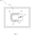
- FIG 3 shows a schematic section of a radar measuring device 300 according to the invention in plan view.
- the semiconductor material 304 is arranged on the carrier plate 303 and is electrically connected to the carrier plate 303 via the bonding wires 305.
- the high-frequency circuit 302 and the radiator element 301 are arranged on the semiconductor material 304.
- the resonator element 306 is arranged above the radiator element 301.
- the radar signals generated in the high-frequency circuit 302 are passed on to the radiator element 301 in order to be amplified from there by the resonator element 306.
- the radar signals reflected from the surface of the material and the radar signals received by the radar measuring device travel the same path, only in opposite directions.
- FIG 4 shows a schematic section of a radar measuring device 400 according to the invention for detecting conditions in containers.
- the radar measuring device 400 comprises a primary radiator 403 for sending and receiving radar signals.
- the primary radiator 403 corresponds in the present case to the one in Figure 2 described primary radiator.
- the radar measuring device 400 also has a two-part dielectric waveguide 404 and 405.
- the radar signal is initially coupled from the primary radiator 403 into the dielectric waveguide 404.
- a filter unit 402 for filtering the radar signals is arranged between the dielectric waveguide 404 and the dielectric waveguide 405.
- the filter unit is designed as a metallic circular waveguide 401.
- the radar signals are coupled from the metallic waveguide 401 into the dielectric waveguide 405.
- the radar signals are forwarded from the dielectric waveguide 405 to the antenna unit (not shown) for transmission and reception.
- the filter unit 402, which is designed as a metallic waveguide 401 filters the radar signal in terms of mode and frequency.
- FIG. 5 shows a schematic section of a radar measuring device 500 according to the invention.
- the radar measuring device 500 comprises a primary radiator 501, a dielectric waveguide 502, a filter unit 503 and an antenna unit 504.
- the Filter unit 503 is designed as a metallic waveguide.
- Antenna unit 504 is designed as a lens antenna.
- Filter unit 503 is arranged between dielectric waveguide 502 and antenna unit 504.
- FIG. 6 shows a schematic section of a radar measuring device 600 according to the invention.
- the radar measuring device 600 comprises a primary radiator 601, a dielectric waveguide 602, a filter unit 603 and an antenna unit 604.
- the dielectric waveguide 602 is arranged between the primary radiator 601 and the filter unit 603.
- the waveguide unit 603 is designed as a metallic waveguide.
- the antenna unit 604 is designed as a dielectric lens.
- the filter unit 603 filters the radar signal with regard to frequency and mode.
- the filter unit 603 receives radar signals from the dielectric lens and sends radar signals to the dielectric lens.
- FIG. 7 shows a schematic section of a radar measuring device 700 according to the invention.
- a metallic housing 701 of the radar measuring device 700 is also shown.
- the radar measuring device 700 also has an interface 702 for power supply and data exchange, for example an M12 interface.
- the radar measuring device 600 in the present case has a plurality of carrier plates 703, 704 and 705, which are used for the power supply, the control and the high-frequency circuit for generating and processing radar signals. These are electrically connected to one another via connectors 706.
- the radar measuring device 700 has a metallic process connection 707 in the lower region of the housing 701.
- the dielectric waveguides 708 and 709 are arranged in the process connection 707, as are the filter unit 710 and the antenna unit 711.
- the antenna unit 711 is in the present case glued to the process connection 707 in a sealing manner.
- the filter unit 710 is in the present case designed as a metallic waveguide.
- the metallic waveguide has an external thread for mounting in the process connection 707.
- the process connection is designed to be connected to a corresponding opening of a container for detecting the fill level.
- Figure 8 shows a section of a radar measuring device 800 according to the invention.
- a housing 801 is also shown.
- the interface 802 and the circuit boards 803 to 805 are arranged.
- the filter unit 806 is designed as a metallic hollow cylinder and is arranged in the metallic process connection by means of a thread.
- the dielectric lens 807 is in turn glued to the process connection in a sealing manner.
- FIG. 9 shows two examples of rectangular waveguides.
- the rectangular waveguide 900 has cylindrically shaped dielectric resonator elements 901 to 903, which are arranged inside the cavity.
- the resonator elements limit the passage frequency upwards.
- the rectangular waveguide 904 has the diaphragms 905-907, which are arranged inside the cavity.
- the diaphragms limit the passage frequency upwards.
Landscapes
- Physics & Mathematics (AREA)
- Engineering & Computer Science (AREA)
- Radar, Positioning & Navigation (AREA)
- Remote Sensing (AREA)
- General Physics & Mathematics (AREA)
- Computer Networks & Wireless Communication (AREA)
- Electromagnetism (AREA)
- Thermal Sciences (AREA)
- Fluid Mechanics (AREA)
- Radar Systems Or Details Thereof (AREA)
Priority Applications (3)
| Application Number | Priority Date | Filing Date | Title |
|---|---|---|---|
| EP23182603.3A EP4484904A1 (fr) | 2023-06-30 | 2023-06-30 | Appareil de mesure radar pour la détection de niveaux de remplissage et/ou de distances |
| CN202410498299.1A CN119223397A (zh) | 2023-06-30 | 2024-04-24 | 用于检测填充物位和距离的雷达测量装置 |
| US18/746,603 US20250004097A1 (en) | 2023-06-30 | 2024-06-18 | Radar measuring device for determining fill levels and/or distances |
Applications Claiming Priority (1)
| Application Number | Priority Date | Filing Date | Title |
|---|---|---|---|
| EP23182603.3A EP4484904A1 (fr) | 2023-06-30 | 2023-06-30 | Appareil de mesure radar pour la détection de niveaux de remplissage et/ou de distances |
Publications (1)
| Publication Number | Publication Date |
|---|---|
| EP4484904A1 true EP4484904A1 (fr) | 2025-01-01 |
Family
ID=87060550
Family Applications (1)
| Application Number | Title | Priority Date | Filing Date |
|---|---|---|---|
| EP23182603.3A Pending EP4484904A1 (fr) | 2023-06-30 | 2023-06-30 | Appareil de mesure radar pour la détection de niveaux de remplissage et/ou de distances |
Country Status (3)
| Country | Link |
|---|---|
| US (1) | US20250004097A1 (fr) |
| EP (1) | EP4484904A1 (fr) |
| CN (1) | CN119223397A (fr) |
Families Citing this family (1)
| Publication number | Priority date | Publication date | Assignee | Title |
|---|---|---|---|---|
| FR3161739A1 (fr) * | 2024-04-25 | 2025-10-31 | Continental Automotive Technologies GmbH | Procédé de détection de la présence d’un liquide dans un contenant au moyen d’un circuit de communication en champ proche |
Citations (11)
| Publication number | Priority date | Publication date | Assignee | Title |
|---|---|---|---|---|
| WO2007085518A2 (fr) * | 2006-01-25 | 2007-08-02 | Endress+Hauser Gmbh+Co.Kg | Dispositif permettant de déterminer et de surveiller le niveau d'un milieu dans un contenant |
| US7864104B2 (en) * | 2005-05-11 | 2011-01-04 | Endress + Hauser Gmbh + Co. Kg | Device for determining and monitoring the level of a medium in a container |
| US20120060600A1 (en) * | 2009-05-25 | 2012-03-15 | Endress + Hauser Gmbh + Co. Kg | Arrangement for measuring fill level with a fill level measuring device working with microwaves |
| US9000775B2 (en) * | 2010-07-13 | 2015-04-07 | Endress + Hauser Gmbh + Co. Kg | Fill-level measuring device for ascertaining and monitoring fill level of a medium located in the process space of a container by means of a microwave travel time measuring method |
| EP2901524B1 (fr) * | 2012-09-25 | 2018-08-22 | Rosemount Tank Radar AB | Jauge de niveau à radar doté d'une antenne directionnelle à deux canaux |
| US10113899B2 (en) * | 2013-12-06 | 2018-10-30 | Endress+Hauser SE+Co. KG | Apparatus for determining fill level of a fill substance in a container with process isolation having at least two plastics |
| EP3483569A1 (fr) * | 2017-11-14 | 2019-05-15 | VEGA Grieshaber KG | Appareil de mesure de niveau de remplissage à séparation de potentielle dans le guide d'ondes |
| WO2019206689A1 (fr) * | 2018-04-26 | 2019-10-31 | Rosemount Tank Radar Ab | Système de jauge de niveau radar à antenne diélectrique |
| EP3077778B1 (fr) * | 2013-12-06 | 2021-03-17 | Honeywell International Inc. | Système de radar adaptatif avec formes d'ondes multiples |
| WO2022122407A1 (fr) * | 2020-12-11 | 2022-06-16 | Endress+Hauser SE+Co. KG | Dispositif de mesure de niveau de remplissage |
| DE102009000733B4 (de) * | 2009-02-09 | 2022-07-07 | Endress+Hauser SE+Co. KG | Parabolantenne für ein Füllstandsmessgerät zur Überwachung und Bestimmung des Füllstandes in einem Behälter |
Family Cites Families (1)
| Publication number | Priority date | Publication date | Assignee | Title |
|---|---|---|---|---|
| US7204140B2 (en) * | 2004-07-01 | 2007-04-17 | Saab Rosemount Tank Radar Ab | Radar level gauge flange |
-
2023
- 2023-06-30 EP EP23182603.3A patent/EP4484904A1/fr active Pending
-
2024
- 2024-04-24 CN CN202410498299.1A patent/CN119223397A/zh active Pending
- 2024-06-18 US US18/746,603 patent/US20250004097A1/en active Pending
Patent Citations (11)
| Publication number | Priority date | Publication date | Assignee | Title |
|---|---|---|---|---|
| US7864104B2 (en) * | 2005-05-11 | 2011-01-04 | Endress + Hauser Gmbh + Co. Kg | Device for determining and monitoring the level of a medium in a container |
| WO2007085518A2 (fr) * | 2006-01-25 | 2007-08-02 | Endress+Hauser Gmbh+Co.Kg | Dispositif permettant de déterminer et de surveiller le niveau d'un milieu dans un contenant |
| DE102009000733B4 (de) * | 2009-02-09 | 2022-07-07 | Endress+Hauser SE+Co. KG | Parabolantenne für ein Füllstandsmessgerät zur Überwachung und Bestimmung des Füllstandes in einem Behälter |
| US20120060600A1 (en) * | 2009-05-25 | 2012-03-15 | Endress + Hauser Gmbh + Co. Kg | Arrangement for measuring fill level with a fill level measuring device working with microwaves |
| US9000775B2 (en) * | 2010-07-13 | 2015-04-07 | Endress + Hauser Gmbh + Co. Kg | Fill-level measuring device for ascertaining and monitoring fill level of a medium located in the process space of a container by means of a microwave travel time measuring method |
| EP2901524B1 (fr) * | 2012-09-25 | 2018-08-22 | Rosemount Tank Radar AB | Jauge de niveau à radar doté d'une antenne directionnelle à deux canaux |
| US10113899B2 (en) * | 2013-12-06 | 2018-10-30 | Endress+Hauser SE+Co. KG | Apparatus for determining fill level of a fill substance in a container with process isolation having at least two plastics |
| EP3077778B1 (fr) * | 2013-12-06 | 2021-03-17 | Honeywell International Inc. | Système de radar adaptatif avec formes d'ondes multiples |
| EP3483569A1 (fr) * | 2017-11-14 | 2019-05-15 | VEGA Grieshaber KG | Appareil de mesure de niveau de remplissage à séparation de potentielle dans le guide d'ondes |
| WO2019206689A1 (fr) * | 2018-04-26 | 2019-10-31 | Rosemount Tank Radar Ab | Système de jauge de niveau radar à antenne diélectrique |
| WO2022122407A1 (fr) * | 2020-12-11 | 2022-06-16 | Endress+Hauser SE+Co. KG | Dispositif de mesure de niveau de remplissage |
Non-Patent Citations (1)
| Title |
|---|
| BORNEMANN J ET AL: "Comparative study of TE/sub mn//sup x/ versus TE/sub mn/-TM/sub mn/ mode analysis and its application to waveguide discontinuity modeling", 19900508; 19900508 - 19900510, 8 May 1990 (1990-05-08), pages 713 - 716, XP010004631 * |
Also Published As
| Publication number | Publication date |
|---|---|
| CN119223397A (zh) | 2024-12-31 |
| US20250004097A1 (en) | 2025-01-02 |
Similar Documents
| Publication | Publication Date | Title |
|---|---|---|
| EP3894807B1 (fr) | Détecteur de niveau de remplissage | |
| DE102017109861A1 (de) | Verfahren und Vorrichtungen für Geschwindigkeits- und/oder Positionserfassung | |
| DE69704649T2 (de) | Antennensignalverteiler und Sende- und Empfangvorrichtung unter Verwendung desselben | |
| EP2435804B1 (fr) | Système de mesure de niveau comportant un appareil de mesure de niveau fonctionnant par micro-ondes | |
| EP3824258B1 (fr) | Module à haute fréquence | |
| WO2014006148A1 (fr) | Couplage étanche au gaz d'un guide d'onde, moudule haute fréquence, radar de niveau de remplissage et utilisation | |
| EP3830894B1 (fr) | Module à haute fréquence | |
| DE112009001919B4 (de) | Anpassungsschaltung sowie Leiterplatte, Sender, Empfänger, Sende-Empfänger und Radarvorrichtung, die die Anpassungsschaltung umfassen | |
| DE10023497A1 (de) | Füllstandsmeßgerät | |
| EP1949491B1 (fr) | Jonction de guides d'ondes | |
| WO2015000656A1 (fr) | Dispositif d'antenne pour appareil de mesure de niveau | |
| WO2007110164A1 (fr) | Transition de guide d'onde avec élément de découplage pour entrées de guide d'onde planes | |
| EP4484904A1 (fr) | Appareil de mesure radar pour la détection de niveaux de remplissage et/ou de distances | |
| DE102014207571A1 (de) | Radarsystem zur Umfelderfassung für ein Fahrzeug sowie Platine für ein solches Radarsystem | |
| EP4735841A1 (fr) | Dispositif radar de mesure de niveau de remplissage pour détecter des niveaux de remplissage dans des récipients | |
| EP3949011B1 (fr) | Module radar à puce hyperfréquence | |
| WO2016082958A1 (fr) | Dispositif de transmission de signaux sortant d'un orifice d'un boîtier métallique | |
| WO2002068913A2 (fr) | Dispositif pour determiner ou controler le niveau de remplissage d'un produit de remplissage dans un contenant | |
| DE102012112218A1 (de) | Füllstandsmessgerät | |
| EP3473988A1 (fr) | Dispositif de mesure d'un niveau de remplissage doté d'une extension d'antenne et de guides d'ondes séparés d'émission et de réception | |
| DE102023134797A1 (de) | Füllstandsmessgerät | |
| DE102014210826B4 (de) | Prüfverfahren für ein Platinensubstrat und Platine, die insbesondere zur Verwendung in einem solchen Prüfverfahren geeignet ist | |
| EP3813188B1 (fr) | Agencement de guide d'ondes et antenne | |
| EP4293818A1 (fr) | Ensemble antenne permettant d'émettre un signal de mesure haute fréquence d'un capteur de mesure | |
| DE102007008202A1 (de) | Testsystem für Radarsensoren |
Legal Events
| Date | Code | Title | Description |
|---|---|---|---|
| PUAI | Public reference made under article 153(3) epc to a published international application that has entered the european phase |
Free format text: ORIGINAL CODE: 0009012 |
|
| STAA | Information on the status of an ep patent application or granted ep patent |
Free format text: STATUS: REQUEST FOR EXAMINATION WAS MADE |
|
| 17P | Request for examination filed |
Effective date: 20240319 |
|
| AK | Designated contracting states |
Kind code of ref document: A1 Designated state(s): AL AT BE BG CH CY CZ DE DK EE ES FI FR GB GR HR HU IE IS IT LI LT LU LV MC ME MK MT NL NO PL PT RO RS SE SI SK SM TR |
|
| STAA | Information on the status of an ep patent application or granted ep patent |
Free format text: STATUS: EXAMINATION IS IN PROGRESS |
|
| 17Q | First examination report despatched |
Effective date: 20250707 |