EP4484919A2 - Systèmes et procédés de détection d'usure d'éléments de réduction d'une machine de réduction de matériau - Google Patents
Systèmes et procédés de détection d'usure d'éléments de réduction d'une machine de réduction de matériau Download PDFInfo
- Publication number
- EP4484919A2 EP4484919A2 EP24205181.1A EP24205181A EP4484919A2 EP 4484919 A2 EP4484919 A2 EP 4484919A2 EP 24205181 A EP24205181 A EP 24205181A EP 4484919 A2 EP4484919 A2 EP 4484919A2
- Authority
- EP
- European Patent Office
- Prior art keywords
- reducing
- wear
- sensor
- sensors
- sensing
- Prior art date
- Legal status (The legal status is an assumption and is not a legal conclusion. Google has not performed a legal analysis and makes no representation as to the accuracy of the status listed.)
- Pending
Links
Images


Classifications
-
- E—FIXED CONSTRUCTIONS
- E01—CONSTRUCTION OF ROADS, RAILWAYS, OR BRIDGES
- E01C—CONSTRUCTION OF, OR SURFACES FOR, ROADS, SPORTS GROUNDS, OR THE LIKE; MACHINES OR AUXILIARY TOOLS FOR CONSTRUCTION OR REPAIR
- E01C23/00—Auxiliary devices or arrangements for constructing, repairing, reconditioning, or taking-up road or like surfaces
- E01C23/06—Devices or arrangements for working the finished surface; Devices for repairing or reconditioning the surface of damaged paving; Recycling in place or on the road
- E01C23/12—Devices or arrangements for working the finished surface; Devices for repairing or reconditioning the surface of damaged paving; Recycling in place or on the road for taking-up, tearing-up, or full-depth breaking-up paving, e.g. sett extractor
- E01C23/122—Devices or arrangements for working the finished surface; Devices for repairing or reconditioning the surface of damaged paving; Recycling in place or on the road for taking-up, tearing-up, or full-depth breaking-up paving, e.g. sett extractor with power-driven tools, e.g. oscillated hammer apparatus
- E01C23/127—Devices or arrangements for working the finished surface; Devices for repairing or reconditioning the surface of damaged paving; Recycling in place or on the road for taking-up, tearing-up, or full-depth breaking-up paving, e.g. sett extractor with power-driven tools, e.g. oscillated hammer apparatus rotary, e.g. rotary hammers
-
- E—FIXED CONSTRUCTIONS
- E01—CONSTRUCTION OF ROADS, RAILWAYS, OR BRIDGES
- E01C—CONSTRUCTION OF, OR SURFACES FOR, ROADS, SPORTS GROUNDS, OR THE LIKE; MACHINES OR AUXILIARY TOOLS FOR CONSTRUCTION OR REPAIR
- E01C23/00—Auxiliary devices or arrangements for constructing, repairing, reconditioning, or taking-up road or like surfaces
- E01C23/06—Devices or arrangements for working the finished surface; Devices for repairing or reconditioning the surface of damaged paving; Recycling in place or on the road
- E01C23/08—Devices or arrangements for working the finished surface; Devices for repairing or reconditioning the surface of damaged paving; Recycling in place or on the road for roughening or patterning; for removing the surface down to a predetermined depth high spots or material bonded to the surface, e.g. markings; for maintaining earth roads, clay courts or like surfaces by means of surface working tools, e.g. scarifiers, levelling blades
- E01C23/085—Devices or arrangements for working the finished surface; Devices for repairing or reconditioning the surface of damaged paving; Recycling in place or on the road for roughening or patterning; for removing the surface down to a predetermined depth high spots or material bonded to the surface, e.g. markings; for maintaining earth roads, clay courts or like surfaces by means of surface working tools, e.g. scarifiers, levelling blades using power-driven tools, e.g. vibratory tools
- E01C23/088—Rotary tools, e.g. milling drums
-
- E—FIXED CONSTRUCTIONS
- E21—EARTH OR ROCK DRILLING; MINING
- E21B—EARTH OR ROCK DRILLING; OBTAINING OIL, GAS, WATER, SOLUBLE OR MELTABLE MATERIALS OR A SLURRY OF MINERALS FROM WELLS
- E21B12/00—Accessories for drilling tools
- E21B12/02—Wear indicators
-
- E—FIXED CONSTRUCTIONS
- E21—EARTH OR ROCK DRILLING; MINING
- E21B—EARTH OR ROCK DRILLING; OBTAINING OIL, GAS, WATER, SOLUBLE OR MELTABLE MATERIALS OR A SLURRY OF MINERALS FROM WELLS
- E21B3/00—Rotary drilling
-
- E—FIXED CONSTRUCTIONS
- E21—EARTH OR ROCK DRILLING; MINING
- E21C—MINING OR QUARRYING
- E21C35/00—Details of, or accessories for, machines for slitting or completely freeing the mineral from the seam, not provided for in groups E21C25/00 - E21C33/00, E21C37/00 or E21C39/00
-
- E—FIXED CONSTRUCTIONS
- E02—HYDRAULIC ENGINEERING; FOUNDATIONS; SOIL SHIFTING
- E02F—DREDGING; SOIL-SHIFTING
- E02F3/00—Dredgers; Soil-shifting machines
- E02F3/04—Dredgers; Soil-shifting machines mechanically-driven
- E02F3/18—Dredgers; Soil-shifting machines mechanically-driven with digging wheels turning round an axis, e.g. bucket-type wheels
- E02F3/20—Dredgers; Soil-shifting machines mechanically-driven with digging wheels turning round an axis, e.g. bucket-type wheels with tools that only loosen the material, i.e. mill-type wheels
-
- E—FIXED CONSTRUCTIONS
- E02—HYDRAULIC ENGINEERING; FOUNDATIONS; SOIL SHIFTING
- E02F—DREDGING; SOIL-SHIFTING
- E02F5/00—Dredgers or soil-shifting machines for special purposes
- E02F5/02—Dredgers or soil-shifting machines for special purposes for digging trenches or ditches
- E02F5/08—Dredgers or soil-shifting machines for special purposes for digging trenches or ditches with digging wheels turning round an axis
-
- E—FIXED CONSTRUCTIONS
- E02—HYDRAULIC ENGINEERING; FOUNDATIONS; SOIL SHIFTING
- E02F—DREDGING; SOIL-SHIFTING
- E02F5/00—Dredgers or soil-shifting machines for special purposes
- E02F5/02—Dredgers or soil-shifting machines for special purposes for digging trenches or ditches
- E02F5/14—Component parts for trench excavators, e.g. indicating devices travelling gear chassis, supports, skids
- E02F5/145—Component parts for trench excavators, e.g. indicating devices travelling gear chassis, supports, skids control and indicating devices
-
- E—FIXED CONSTRUCTIONS
- E02—HYDRAULIC ENGINEERING; FOUNDATIONS; SOIL SHIFTING
- E02F—DREDGING; SOIL-SHIFTING
- E02F9/00—Component parts of dredgers or soil-shifting machines, not restricted to one of the kinds covered by groups E02F3/00 - E02F7/00
- E02F9/08—Superstructures; Supports for superstructures
- E02F9/10—Supports for movable superstructures mounted on travelling or walking gears or on other superstructures
- E02F9/12—Slewing or traversing gears
- E02F9/121—Turntables, i.e. structure rotatable about 360°
- E02F9/126—Lubrication systems
-
- E—FIXED CONSTRUCTIONS
- E02—HYDRAULIC ENGINEERING; FOUNDATIONS; SOIL SHIFTING
- E02F—DREDGING; SOIL-SHIFTING
- E02F9/00—Component parts of dredgers or soil-shifting machines, not restricted to one of the kinds covered by groups E02F3/00 - E02F7/00
- E02F9/26—Indicating devices
-
- E—FIXED CONSTRUCTIONS
- E02—HYDRAULIC ENGINEERING; FOUNDATIONS; SOIL SHIFTING
- E02F—DREDGING; SOIL-SHIFTING
- E02F9/00—Component parts of dredgers or soil-shifting machines, not restricted to one of the kinds covered by groups E02F3/00 - E02F7/00
- E02F9/26—Indicating devices
- E02F9/264—Sensors and their calibration for indicating the position of the work tool
-
- E—FIXED CONSTRUCTIONS
- E02—HYDRAULIC ENGINEERING; FOUNDATIONS; SOIL SHIFTING
- E02F—DREDGING; SOIL-SHIFTING
- E02F9/00—Component parts of dredgers or soil-shifting machines, not restricted to one of the kinds covered by groups E02F3/00 - E02F7/00
- E02F9/26—Indicating devices
- E02F9/267—Diagnosing or detecting failure of vehicles
-
- E—FIXED CONSTRUCTIONS
- E02—HYDRAULIC ENGINEERING; FOUNDATIONS; SOIL SHIFTING
- E02F—DREDGING; SOIL-SHIFTING
- E02F9/00—Component parts of dredgers or soil-shifting machines, not restricted to one of the kinds covered by groups E02F3/00 - E02F7/00
- E02F9/28—Small metalwork for digging elements, e.g. teeth scraper bits
- E02F9/2866—Small metalwork for digging elements, e.g. teeth scraper bits for rotating digging elements
-
- E—FIXED CONSTRUCTIONS
- E21—EARTH OR ROCK DRILLING; MINING
- E21C—MINING OR QUARRYING
- E21C27/00—Machines which completely free the mineral from the seam
- E21C27/20—Mineral freed by means not involving slitting
- E21C27/24—Mineral freed by means not involving slitting by milling means acting on the full working face, i.e. the rotary axis of the tool carrier being substantially parallel to the working face
-
- G—PHYSICS
- G01—MEASURING; TESTING
- G01N—INVESTIGATING OR ANALYSING MATERIALS BY DETERMINING THEIR CHEMICAL OR PHYSICAL PROPERTIES
- G01N3/00—Investigating strength properties of solid materials by application of mechanical stress
- G01N3/56—Investigating resistance to wear or abrasion
Definitions
- the present disclosure relates generally to systems and methods for sensing wear in machines designed to reduce or break-down material. More particularly, the present disclosure relates to systems and methods for sensing wear of reducing elements used by excavation machines such as surface excavation machines.
- Relatively hard materials are often processed for mining and construction.
- the variety of materials include rock, concrete, asphalt, coal and a vareity of other types of earth formations.
- a number of different methods for reducing the size of these hard materials have been developed.
- One traditional material size reduction method has been to drill relatively small holes in the material which are then packed with an explosive that is ignited resulting in a rapid and cost effective method of size reduction.
- disadvantages to this technique including the inherent risk of injuries, the production of undesireable noise, vibrations, and dust, and the fact that this process is difficult to utilize in situations where space is limited or where there is a potential risk of causing other gases to ignite.
- the main alternative has been the use of reducing machines having rotary reducing components that move rigid and specialized reducing elements through paths of travel.
- the reducing components can include rotating drums that move the reducing elements through circular paths of travel. Such drums are typically attached to their correspondng machines so that the positions and orientations of the drum can be controlled to bring the reducing elements into contact with the material being reduced.
- Alternative reducing components can include boom-mounted chains that carry reducing elements. The chains are typically driven/rotated about their corresponding booms. The reducing elements are mounted to and move along the paths of travel defined by the chains. In use, the booms are moved (e. g., through a pivoting motion) to positions where the reducing elements are brought into contact with the material being reduced.
- An example machine of the type described above is disclosed at U.S. Patent No. 7,290,360 .
- the disclosed machine is a surface excavation machine used for applications such as surface mining, demolishing roads, terrain leveling, and prepping sites for new construction or reconstruction by removing one or more layers of material.
- Surface excavation machines of this type provide an economical alternative to blasting and hammering and provide the advantage of generating a consistent output material after a single pass. This can reduce the need for primary crushers, large loaders, large haul trucks and the associated permits to transport materials to crushers.
- the reducing elements of reducing machines have been developed to withstand the impact loads and abrasion associated with material reduction activities.
- Reducing elements can be constructed in a variety of shapes and sizes and have been labeled with various terms including cutters, chisels, picks, teeth etc.
- Typical reducing elements include leading impact points or edges and bases.
- the bases are constructed to fit into mouting structures that are integrated with drums or chains used to carry the reducing elements during material reducing applications.
- the harsh environment associated with material reducing applications virtually guarantees that the reducing elements will wear down over time.
- the reducing elements are designed to be replaceable, while the mounting structures are not intended to be replaced frequently. For example, when a given reducing element becomes worn, it is removed from its corresponding mounting structure and replaced with a new, unworn reducing element.
- the tips or edges of the reducing elements have a harder construction (e.g., a solid carbide construction) than the bases of the reducing elements.
- a harder construction e.g., a solid carbide construction
- the leading points or edges are exposed to the majority of the impacts and abrasion action.
- the bases are exposed to more impacts and abrasive action.
- a variety of potential problems can arise when this occurs, including that the bases is less efficient at breaking the material causing inefficient operation. This inefficiency can result in generation of sparks and/or excessive heat which can lead to a risk of explosions, as may occur in a coal mining application where methane gas can be present.
- the bases will typically wear relatively quickly as compared to the leading points or tips.
- aspects of the present disclosure relate to improved methods for sensing (e.g., detecting, measuring, monitoring, tracking, etc.) the wear state of a reducing element (i.e., a cutter, a pick, a chisel, a blade, a tooth, etc.) of a material reducing machine.
- the material reducing machine is an excavation machine such as a surface excavation machine used for mining, surface mining, terrain leveling, road milling, or other applications.
- the material reducing machine can include a trencher, a rock wheel, a horizontal grinder, a tub grinder, a chipper or other type of machine that utilizes reducing elements to process a material by breaking up or otherwise reducing the size of the material.
- the present disclosure relates generally to sensing systems for sensing reducing element wear in a material reducing machine.
- the material reducing machine includes a rotary component such as a drum or chain that carries the reducing elements.
- the reducing element wear sensing system provides an indication of the level of reducing element wear such that an operator can readily recognize when one or more of the reducing elements are in need of replacement.
- the level of reducing element wear can be displayed graphically or numerically to provide a qualitative indication of the specific level of wear for each reducing element.
- the system can provide an indication when as worn beyond a predetermined level such that replacement is recommended.
- sensors in accordance with the principles of the present disclosure provide data regarding the general wear state of a given reducing element without determining or measuring the position of a specific geometric point or profile of the reducing element.
- the sensors can sense general physical characteristics (e.g., volume, mass, surface area, etc.) of the reducing elements without measuring the position of a given point on a given reducing element. Sensors of this type can be used effectively in harsh environments such as those encountered by material reducing machines (e.g., surface excavation machines, trenchers, rock wheels, horizontal grinders, tub grinders or other material reduction machines).
- sensing systems in accordance with the principles of the present disclosure can be used to assess reducing element wear of a reducing machine while the reducing machine is conducting reducing operations.
- sensing systems in accordance with the principles of the present disclosure can provide real-time wear information regarding the reducing elements of a reducing machine while the reducing machine is being operated.
- sensors of the sensing system are mounted in a sensing position and need not be moved from the sensing system to a stowed position when the reducing machine is used to reduce material.
- reducing element wear systems used in systems in accordance with the principles of the present disclosure can include inductive sensors.
- sensing systems in accordance with the principles of the present disclosure can compensate for factors such as temperature and reducing element speed.
- sensors are placed in close proximity to one another and also in close proximity to multiple different reducing elements.
- various strategies can be utilized to provide usable wear data regarding individual reducing elements.
- filtering strategies can be utilized to filter out data corresponding to reducing elements not intended to be sensed by a given sensor.
- at least one sensor is provided for each reducing element.
- At least one sensor is provided for each reducing path defined by one or more reducing elements of a reducing machine.
- sensors are positioned in close proximity to one another and operating strategies are utilized to reduce or minimize interference between adjacent sensors.
- sensors can be selectively activated and deactivated to minimize interference between adjacent sensors.
- the sensors can also be operated in sets so that multiple sensors can be activated at once without having adjacent sensors activated concurrently.
- a center to center spacing of the sensors is smaller than an effective sensing distance of the sensors.
- a spacing between reducing paths of the reducing elements of the material reducing machine is smaller than an effective sensing distance of the sensors used to sense wear of the reducing elements.
- systems in accordance with the principles of the present disclosure can include structure for protecting the sensors of the sensing system during material reducing operations.
- breaker bars or other blocking structures can be provided for preventing material from damaging the sensors.
- the breaker bars can be positioned closer to a reducing circle or cylinder of the material reducing machine than the sensors.
- the sensors can also be protected by a rugged, protective housing that covers the sensors but does not interfere with the sensors' ability to sense the reducing elements.
- the sensors can sense the reducing elements through the protective housings.
- protective housings are made of a dielectric material such as plastic and the sensors are inductive sensors.
- inductive wear sensors are used.
- the inductive wear sensors can have operating ranges of at least 75 mm when used with a standard target as defined by the sensor manufacturer.
- wear systems in accordance with the principles of the present disclosure can use inductive sensors having effective sensing distances less than 100 mm.
- the inductive sensors have effective operating distances greater than 50 mm.
- Other aspects of the present disclosure relate to a wear sensing system including a multi-level wear sensor protection system.
- the multi-level wear sensor protection system includes a first level of protection, a second level of protection, and a third level of protection.
- the first level of protection includes an initial barrier layer including a plurality of sheet segments made of a polycarbonate material.
- the second level of protection includes a side-by-side arrangement of trays positioned behind the initial barrier layer.
- the trays can be configured to absorb impacts that are transmitted through the initial barrier layer to prevent the impacts from impacting upon the sensors.
- the third level of protection includes a relief structure for accommodating impacts that are transmitted through both the initial barrier layer and the trays.
- the relief structure can be positioned behind the trays for accommodating movement of the trays in response to an impact that passes through the initial barrier layer and the trays.
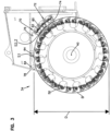
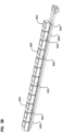
- FIG. 1 illustrates a surface excavation machine 20 that can utilize a reducing element wear sensing system in accordance with the principles of the present disclosure.
- the surface excavation machine 20 includes a tractor 19 having a main chassis 22 (i.e., a mainframe) including a front end 24 and a rear end 26.
- the main chassis 22 is supported on a ground drive system (i.e., a propulsion system) that preferably includes a plurality of propulsion structures such as wheels or tracks 30 for propelling the machine 20 over the ground.
- An operator cab 32 is positioned at a top side of the main chassis 22.
- An excavation tool 34 is mounted at the rear end 26 of the main chassis 26.
- the excavation tool 34 includes an excavation drum 38 that is rotatably driven (e.g., by hydraulic motors) about a drum axis 40.
- the excavation drum 38 carries a plurality of reducing elements 42 suitable for cutting rock.
- the excavation drum 38 can be mounted to a boom that can be pivoted between a lowered excavating position (see Fig. 1 ) and a raised transport position (not shown).
- a shroud 78 at least partially surrounds/encloses the excavation drum 38.
- the reducing elements 42 are depicted as teeth having leading tips 50 supported on bases 52.
- the leading tips 50 can be harder than the bases 52.
- leading tips 50 can be solid, carbide inserts while the bases 52 can be hardened steel.
- the reducing elements 42 are removably mounted to the excavation drum 38.
- the reducing elements 42 can be fastened within mounting structures such as pockets 54 integrated with the excavation drum 38.
- the surface excavation machine 20 In use of the surface excavation machine 20, the surface excavation machine 20 is moved to an excavation site while the excavation tool 34 is in the transport position. When it is desired to excavate at the excavation site, the excavation tool 34 is lowered from the transport position to the excavation position (see Fig. 1 ). While in the excavation position, the excavation drum 38 is rotated in a direction 46 about the axis 40 such that the excavation drum 38 uses a down-cut motion to remove a desired thickness T of material. As the excavation machine 20 moves in a forward direction 47, excavated material passes under the drum 38 and is left behind the surface excavation machine 20. During the excavation process, the tracks 30 propel the surface excavation machine 20 in the forward direction 47 thereby causing a top layer of material having a thickness T to be excavated. It will be appreciated that example excavation applications for which the surface excavation machine 20 can be used to include surface mining, road milling, terrain leveling, construction preparation and other activities. In other examples, the drum can be configured to excavate using an up-cut motion.
- the leading tips 50 of the reducing elements 42 define a reducing boundary B (e.g., reducing circle or cylinder) of the excavation tool 34.
- the reducing boundary B corresponds to the generally cylindrical boundary transcribed by the leading tips 50 of the reducing elements 42 as the drum 38 is rotated about the drum axis 40.
- the reducing boundary B can have a reducing diameter D.
- the leading tips 50 of the reducing elements 42 also define reducing paths of the excavation tool 34.
- a reducing path is the path that the tip of a reducing element follows/defines when the drum is rotated.
- Each reducing path coincides with a reducing path plane that is perpendicular to the drum axis 40 and that passes through the leading tip 50 of the reducing element 42 that defines the reducing path.
- Example reducing path planes P1, P2, P3 and P4 for four different reducing paths are depicted at Figure 2 .
- the paths correspond to four different reducing elements 42.
- a sensor array 61 can be provided within the shroud 78 near the reducing boundary B.
- a reducing path can be defined by a single reducing element 42 and a corresponding sensor of the sensor array 61 can be aligned with the reducing path so as to be capable of sensing the reducing element 42 when the reducing element 42 passes by the sensor as the reducing element 42 is rotated about the reducing boundary B by the drum 38.
- each reducing path of the excavation tool 34 can have a corresponding separate sensor.
- two or more reducing elements 42 can be provided along a given reducing path.
- the reducing path planes P1, P2, P3 and P4 respectively coincide with reducing paths of reducing elements T1, T2, T3 and T4.
- the sensor array 61 can include separate sensors 60 corresponding to each of the reducing paths.
- the sensors 60 can have effective sensing distances Y that are longer than a path spacing PS between the reducing path planes.
- the sensors 60 can be arranged in multiple rows (e.g., three rows R1, R2 and R3) that extend along the axis of rotation 40 of the drum.
- the sensors 60 can be spaced a spacing distance Z from the reducing boundary B.
- the spacing distance Z is less than the effective sensing distance Y.
- the effective sensing distance Y can be larger than the path spacing PS defined between the reducing path planes.
- the sensors 60 of adjacent rows can be staggered relative to one another in an orientation that extends along the axis of rotation 40.
- adjacent reducing paths are not assigned to sensors in the same row.
- reducing path plane P 1 aligns with sensor S1 of the first row R1
- reducing path plane P2 aligns with sensor S2 of the second row R2
- reducing path plane P3 aligns with sensor S3 of the third row R3
- sensor S4 aligns with sensor S4 of the first row R1.
- This pattern can repeat.
- the sensors 60 of the array can be arranged to have center-to-center sensor spacings measured along the axis of rotation 40 that match the path spacings PS.
- the effective sensing distances Y of the sensors 60 can be larger than the sensor spacings SS.
- the reducing elements 42 each have a metal construction and the sensors 60 are inductive sensors.
- the sensors 60 can generate alternating electromagnetic fields through which the reducing elements 42 pass as the reducing elements 42 are rotated about the axis of rotation 40 by the drum 38.
- the reducing elements 42 each have a metallic construction, when the reducing elements 42 pass through the electromagnetic fields of the sensors 60, eddy currents form on the surface of the reducing elements 42.
- the amount of energy that is transferred by this phenomenon is directly dependent upon the surface area of the reducing element 42 passing through the field.
- the amount of energy transferred from the magnetic field can be sensed by the inductive sensor and is represented by a decrease in electric current at the inductive sensor.
- the amount of energy transferred is dependent upon the size of the object passing through the magnetic field
- the amount of current reduction sensed by the sensor as a reducing element passes through the magnetic field is representative of the size of the reducing element.
- the surface area of the reducing element 42 passing through the magnetic field of its corresponding sensor is reduced such that less energy is transferred to the reducing element as the reducing element passes through the magnetic field. Since less energy is transferred to the reducing element, a smaller reduction in current is sensed by the inductive sensor.
- the surface excavation machine 20 can include a wear sensing system 70 in accordance with the principles of the present disclosure.
- the wear sensing system 70 can include a hanger arrangement 72 for mounting sensor modules 74 to the surface excavation machine 20.
- the sensor modules 74 are mounted at an interior surface 76 of the shroud 78 that at least partially surrounds the drum 38.
- the hanger arrangement 72 includes a plurality of rails 80 (e.g., tracks) having lengths that extend along the drum axis 40.
- the rails 80 define channels 82 in which a row of sensor modules 74 are received.
- the sensor modules 74 can be arranged in an array having three parallel rows of R1, R2 and R3 of sensor modules 74.
- the rows R1, R2 and R3 correspond to channels C1, C2 and C3 defined by the rails 80 of the hanger arrangement 72.
- the sensor modules 74 can be coupled (e.g., pinned or otherwise fastened) together and can be loaded into the hanger arrangement 72 by sliding the rows of sensor modules 74 longitudinally into the channels C1, C2 and C3. It will be appreciated that openings can be provided in end walls of the shroud 78 for allowing the sensor modules 74 to be inserted into the channels C1, C2 and C3.
- the rows R1, R2 and R3 of sensor module 74 are slid along the channel C1, C2, C3 in an orientation that extends along the drum axis 40.
- the sensor modules 74 of adjacent rows can be staggered relative to one another.
- the wear sensing system 70 can also include blocking structure for preventing debris of substantial size from impacting the sensor modules 74.
- material breaking structures are attached to the interior surface 76 of the shroud 78 at a location upstream from the sensor module 74.
- the material breaking structures are positioned at a spacing S1 from the reducing boundary B defined by the reducing elements 42 and the sensor modules 74 are positioned at a spacing S2 from the reducing boundary B defined by the reducing elements 42.
- the spacing S2 is larger than the spacing S1.
- the spacing S2 is at least 25%, 50% or 75% larger than the spacing S1.
- the spacing S2 is at least 1/8 th of an inch or at least 2/8 th of an inch or at least 3/8 th of an inch larger than the spacing S1. In certain examples, the spacing S2 is about 5/8 th of an inch and the spacing S1 is about one inch.
- the breaking structure can include a plurality of breaker bar structures mounted to the interior side of the shroud 78.
- Figure 3 shows a breaker bar arrangement including first and second breaker bar structures 84.
- Each of the breaker bar structures 84 has a length that extends along the drum axis 40.
- the breaker bar structures 84 each include three breaker bar sections 84A, 84B and 84C that are aligned with one another to form the length of the breaker bar structure 84.
- Each of the breaker bar sections 84A, 84B and 84C includes a mounting bar 86 secured to the shroud 78 by reinforcing gussets 88.
- Each of the breaker bar sections 84A, 84B and 84C also includes an impact bar 90 fastened to the mounting bar 86.
- the impact bars 90 are positioned the spacing S1 from the reducing diameters D and are adapted to be impacted by material carried by the reducing elements 42 over the top side of the drum 38 during material reducing operations. As the material is impacted by the impact bars 90, the material is reduced in size such that the material is sufficiently small so as to not extend outwardly from the drum 38 a distance greater than the spacing S1. In this way, the material is prevented from significantly impacting the sensor modules 74.
- the impact bars 90 are secured to the mounting bars 86 by fasteners so that the impact bars can be readily removed and replaced as the impact bars 90 wear.
- the two breaker bar structures 84 are spaced relative to one another about the circumference of the drum 38 such that one of the breaker bars structures 84 is positioned downstream of the other of the breaker bar structures 84. In this way, material is initially impacted by the upstream breaker bar 84 and then is subsequently impacted by the downstream breaker bar structure 84.
- FIGs 5-9 illustrate one of the sensor modules 74.
- the sensor module 74 is configured to hold two of the sensors 60.
- Each of the sensors 60 can include a separate magnetic coil 63 (see Figure 4 ).
- the sensor module 74 includes structure for housing and protecting the magnetic coils.
- the sensor module 74 includes a housing 100 including first and second chambers or sections 102, 104 for housing the coils 63 of the inductive sensors 60.
- the housing 100 is preferably made of a dielectric material through which magnetic fields generated by the coils 63 of the sensors 60 can be readily transmitted.
- housing 100 is made of a hard plastic material that provides impact protection to the sensors 60 while concurrently allowing magnetic fields generated by the sensors 60 to pass through the housing 100.
- the housing 100 includes flanges 106 for engaging the rails 80 of the hanger arrangement 72 to retain the sensor modules 74 within the channels C1-C3. Electrical contacts and wiring can be provided on a back side 108 of the sensor module 74 for allowing the sensor module to be electrically connected to a control system having suitable control circuitry for controlling operation of the sensors 60.
- a metal backing plate 110 can be mounted at a back side of the housing 100.
- the coils 63 of the sensor 60 can be positioned a distance from the reducing boundary B that is equal to the spacing S2 plus the thickness of the front wall of the housing 100.
- the front wall of the housing has a thickness of about 1 ⁇ 4 of an inch and the sensors 60 are spaced about 1.25 inches from the reducing boundary B. It will be appreciated that in other examples, different spacings can be utilized depending upon the type of sensor used, the material being processed and the configuration of the reducing machine.
- Figure 13 is a graph showing an output curve 198 of an inductive sensor at room temperature for a standard target.
- the output curve 198 of the graph of Figure 13 shows the sensor output as a standard target is placed at different spacings directly in front of the sensor thereby causing the sensor to generate different outputs.
- the inductive sensor output has a maximum value shown by line 200. As the standard target is moved progressively closer to the inductive sensor, the inductive sensor output gradually reduces in magnitude.
- the impedance of the coil of the inductive sensor 60 changes with temperature.
- changes in temperature modify the output curve of the inductive sensor.
- the output curves of the inductive sensor move to the left and have steeper slopes as the temperature decreases.
- line 210 corresponds to a temperature of 122° F
- line 212 corresponds to a temperature of 68° F
- line 214 corresponds to a temperature of 32° F.
- the curves 210, 212 and 214 show outputs of a sensor when detecting a standard target at different distances for the different temperatures mentioned above.
- inductive sensor output between a worn reducing element and a new reducing element can be small enough that temperature variations have a meaningful impact when assessing wear levels. Therefore, aspects of the present disclosure relate to using algorithms, look up tables or other means for compensating for temperature variations when monitoring reducing element wear.
- temperature sensors can be provided at the inductive sensor coils to provide an indication of the temperatures of the inductive sensor coils.
- ambient temperature or another temperature associated with the reducing machine can be used to approximate the temperature of the coils of the inductive sensors.
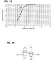
- Figure 15 shows an output curve 199 representing the output of an inductive sensor when sensing a reducing element at different distances from the inductive sensor.
- the reducing element is not offset from the inductive sensor (i.e., the coil of the inductive sensor and the reducing element are both aligned along a common plane corresponding to a reducing path of the reducing element).
- the reducing element used to provide the data of the graph of Figure 15 has a smaller area than the standard target used to provide the data of Figure 13 .
- the sensor output curve 199 depicted at the graph of Figure 15 has a steeper slope than the slope of the curve 198 depicted at Figure 13 .
- the coils of the inductive sensors can be placed at a center-to-center spacing measured along the axis of rotation 40 of the drum 38 that is smaller than the effective sensing distances of the inductive sensors and is also smaller than the widths of the magnetic fields generated by the inductive sensors.
- an inductive sensor aligned with a given reducing path can sense a reducing element corresponding to the reducing path, but also can sense reducing elements corresponding to adjacent reducing paths.
- the slope of the output curve generated by the inductive sensor decreases as the lateral offset distance of the reducing element increases.
- curve 300 shows the output response of an inductive sensor when a standard target is positioned at different distances from the inductive sensor while the standard target has zero lateral offset from the inductive sensor.
- output curve 302 shows the output for the inductive sensor when the same target is positioned at the same outward distances as the output curve 300 but at a 2 inch lateral offset from the inductive sensor.
- the curves between the output curves 300, 302 show the effect of laterally offsetting the target from the inductive sensor.
- Figure 17 shows three sensor output curves 304, 306 and 308.
- the sensor outputs for generating the curve 304 were generated by positioning a standard target at different distances from the inductive sensor while maintaining zero lateral offset.
- the inductive sensor outputs corresponding to the curve 306 were generated by positioning a reducing element 310 (see Figure 18 ) at different distances from the inductive sensor while maintaining a lateral offset of zero.
- the inductive sensor outputs corresponding to the curve 308 were generated by positioning a reducing element 312 ( Fig. 18 ) at different outward spacings from the inductive sensor while maintaining a lateral offset of zero. Since the reducing element 310 is thicker than the reducing element 312, the curve 306 has a less steep slope than the curve 308.
- Figure 17 also illustrates a technique for assessing reducing element wear using the output from the inductive sensor.
- line 314 represents a baseline value for the tooth 310 when the tooth is new. This baseline value can be stored in memory of a control system (e.g., a computer, a processor, or other electronic device) and used to control operation of the wear sensing system.
- Line 316 is representative of an output of the inductive sensor when the tooth 310 becomes worn. In one example, the tooth 310 wears about 1 ⁇ 2 an inch between the line 314 and the line 316. In use, when the output value generated by the inductive sensor reaches the line 316, the operator can be notified that the corresponding tooth 310 should be replaced.
- Line 318 corresponds to an output from the inductive sensor when the reducing element 312 is new.
- Line 320 corresponds to an output from the inductive sensor when the reducing element 312 has worn to a state where the reducing element 312 should be replaced.
- a controller of the reducing element wear sensing system can monitor the outputs of the inductive sensor corresponding to the tooth 312 and can alert an operator that the tooth 312 should be replaced once the output of the inductive sensor reaches the line 320.
- the outputs of the inductive sensor can be modified by algorithms, look up tables or other means to compensate for factors such as temperature and speed.
- the speed at which the reducing element is traveling when the reducing element passes through the alternating magnetic field of the inductive sensor can also affect the output of the sensor. For example, as the rotational speed of the drum is increased without changes an outward spacing between the inductive sensor and the reducing element being sensed, the change in current sensed by the sensor as the reducing element passes through the magnetic field is reduced. To overcome this factor, an algorithm can be used to modify the output of the inductive sensor to compensate for the rotational speed of the drum.
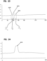
- Figure 21 shows a reducing element 42 interfering with the magnetic field of a sensor 60 and therefore being detected by the sensor 60.
- the reducing element 42 is shown at an outward spacing distance d1 and a lateral spacing distance of zero.
- Figure 22 shows an output of the inductive sensor with the reducing element at the position of Figure 21.
- Figure 19 shows the reducing element 42 laterally offset from the sensor 60 by a lateral spacing distance d2.
- the reducing element 42 is also offset from the inductive sensor 60 by the outward spacing distance d2.
- the outward spacing distance d1 is the same at Figures 19 and 21.
- Figure 20 shows an output of the inductive sensor 60 with the reducing element 42 in the position of Figure 19 .
- a comparison of Figures 20 and 22 shows that an output signal 401 generated by the sensor 60 when the reducing element 42 is directly in line with the inductive sensor 60 has a larger variance as compared to a non-sensing reading 401 of the sensor 60 than a corresponding output signal 402 generated by the inductive sensor 60 when the reducing element 400 is positioned at the same outward spacing distance d1 but also at a lateral spacing distance d2.
- the graph of Figure 20 also demonstrates that inductive sensors 60 are capable of sensing reducing elements that are laterally offset from the sensors but still within the magnetic field of the sensor.
- reducing elements that are laterally offset from a given inductive sensor 60 can be detected by the inductive sensor 60 as the reducing elements move past the sensor 60.
- the cutting paths defined by the reducing elements 42 can be sufficiently close together that one of the inductive sensors 60 can detect the reducing elements corresponding to three or more of the reducing paths.
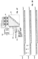
- Figure 23 shows an initial, unfiltered sensor output profile for the inductive sensor 60 for one rotation of the drum 38. As the drum 38 rotates, the inductive sensor 60 senses the reducing element 42 that is aligned with the inductive sensor 60.
- the sensor 60 also senses the reducing element 42 corresponding to the reducing path that is offset to the left of the inductive sensor 60 and the reducing element 42 that corresponds to the reducing path offset to the right of the sensor 60. Because the left and right reducing elements are laterally offset from the sensor 60, signal readings 450B and 450C corresponding to such reducing elements have a smaller variance in magnitude as compared to a reading 450A corresponding to the aligned reducing element. As indicated at Figure 23 , rotational positions ⁇ a , ⁇ b and ⁇ c of the center, left and right reducing elements are determined and saved in memory.
- the magnitudes of the readings 450A, 450B and 450C are compared and the reading 450A with the greatest variance from zero is selected.
- the rotational position ⁇ a of the highest reading 450A is saved in memory.
- the readings 450B and 450C can then be filtered out as shown at Figure 24 . Thereafter, the control system will only look for inductive sensor reading values corresponding to the aligned reducing element at the rotational position ⁇ a . If the system does not detect a reducing element at the rotational position ⁇ a , then the operator can be notified that the aligned reducing element is missing. As the reducing element wears, the magnitude of the signal reading 450A at rotational position ⁇ a will change.
- a certain magnitude of change of the signal reading 450A as compared to a base-line signal reading value is indicative of the reducing element being worn to a point where the reducing element 42A should be replaced. At this point, the operator can be notified that the reducing element 42A should be changed.
- the inductive sensors 60 are positioned sufficiently close to one another that the magnetic fields of adj acent sensors 60 overlap one another. Thus, if all the sensors 60 were operated simultaneously, the magnetic fields of adj acent sensors could interfere with one another. To prevent this type of magnetic interference, in certain examples, all of the sensors 60 are not operated at the same time.
- each of the sensors 60 can be individually operated such that readings are individually taken with respect to each of the reducing paths.
- the controller can use a control protocol that repeatedly cycles through the sensors with each sensor being individually actuated for at least one rotation of the drum 38.
- steps or groups of the sensors 60 can be simultaneously actuated and the control system can cycle through the groups of sensors 60.
- the sensors of each group can be selected based on the relative positioning of the sensors and the positioning of their corresponding magnetic fields. Specifically, the sensors of any given set are selected so that the magnetic fields of the sensors within the set do not interfere with one another.
- Figures 25-30 relate to a system having multiple sets of sensors 60 that are sequentially energized in de-energized. As shown at Figures 25 , 27 , and 29 , only a portion of the length and the circumference of the drum 38 are depicted in a laid-flat view. For example, only about 90° of the circumference of the drum is depicted and only 1 ⁇ 4 of the length of the drum is depicted. The depicted portion of the drum includes reducing elements A1, B1, C1, A2, B2, C2, A3, B3, and C3.
- the sensing system includes a first set of sensors A, a second set of sensors B and a third set of sensors C that all interface with a controller 500.
- the controller 500 controls the operational speed of the drum 38 via a hydraulic motor 502 and a gear box 504.
- the controller also controls operation of the inductive sensor sets A, B and C. For example, during a first sensing phase, the inductive sensors corresponding to set A are activated and the inductive sensors corresponding to sets B and C are deactivated. With the sensors of set A activated and the sensors of sets B and C deactivated, near readings are taken for the reducing elements A1, A2 and A3 as shown at Figure 26 and no readings are taken for the reducing elements corresponding to sets B and C.
- the controller implements a second phase of sensing in which sensor sets A and C are de-energized, and sensor set B is energized ( Fig. 27 ).
- the controller takes wear readings (e.g., input 2 from the inductive sensors of set B) for reducing elements B1, B2 and B3 as shown at Figure 28 .
- the input 2 values correspond to the wear levels of reducing elements B1, B2 and B3.
- the controller can have pre-saved information relating to the rotational positions of the reducing elements B1, B2 and B3.
- the controller can compare sensed wear level values generated by the sensor set B corresponding to each of the reducing elementsB1, B2 and B3 and can compare such values to base level wear values of the reducing elements B1, B2 and B3.
- the base level wear values can correspond to values established when the reducing elements B1, B2 and B3 were initially installed on the drum 38.
- the controller can use algorithms or other means to compensate for variations associated with temperature, the rotational speed of the drum or other factors. Once wear readings for the reducing elements for B1, B2 and B3 have been established, the controller can stop the second phase of sensing and move to a third phase of sensing.
- Figure 29 shows the system in a third phase of sensing.
- the sensor sets A and B are de-energized, and the sensor set C is energized.
- the controller can access input 3 values from the sensors of set C relating to the wear levels of the reducing elements C1, C2 and C3 (see Fig. 30 ).
- the wear level values are generated by the sensor set C as the drum is rotated.
- the sensed wear level values of the reducing elements C1, C2 and C3 can be compared to base-line wear level values for the reducing elements C1, C2 and C3.
- the base-line wear level values for the reducing elements C1, C2 and C3 can be established by the system when the reducing elements C1, C2 and C3 are initially installed on the drum 38. If the sensed wear level values indicated by input 3 deviate from the base-line wear level values by a predetermined amount, the system can indicate that replacement of one or more of the reducing elements C1, C2 and C3 is recommended or required.
- certain readings taken by inductive sensors in accordance with the principles of the present disclosure are general in nature and do not identify the position of a specific geometric point on any of the reducing elements. Instead, the readings taken by the sensors provide a general indication of the overall surface area of a given reducing element that passes through the magnetic field of the sensor corresponding to the reducing element.
- the reading can vary depending upon the size and shape of the reducing element. In this regard, different wear patterns on the reducing element can yield similar readings. For example, similar yield readings may be yielded if portions of the base wear away while the tip remains intact or if the tip is removed and the base remains fully intact.
- sensing systems in accordance with the principles of the present disclosure provide a good indication of general wear while concurrently not using precise optical technology that is not compatible with use during normal operation of the reducing machine.
- sensing systems in accordance with the principles of the present disclosure can be used while their corresponding material reducing machines are being used to reduce materials and do not require material reduction operations to be stopped to allow for wear sensing.
- sensing configurations in accordance with the principles of the present disclosure have rugged constructions that can remain in a sensing position during material reduction operations and are not required to be moved to a stowed position during material reduction operations.
- a reducing element is initially installed on a drum or chain.
- the drum and/or chain is then rotated and a base-line wear reading is taken with respect to the installed reducing element.
- the base-line wear reading can be taken using a sensor such as an inductive sensor.
- a temperature value e.g., a temperature representative of the coil temperature
- a rotational speed of the drum or chain are identified.
- the base-line wear reading as well as the temperature value and the rotational speed value can be saved in memory.
- the machine can then be operated to perform material reduction operations. While performing material reduction operations, a real-time wear reading can be taken with respect to the reducing element using the sensor.
- Real-time temperature and rotational speed readings can also be taken. Once the real-time readings have been taken, the real-time wear reading and the base-line wear reading can be compared to assess a wear level of the reducing element and to determine whether the reducing element has worn to the point where the reducing element is recommended or required to be replaced. In comparing the real-time wear reading to the base-line wear reading, the controller can make adjustments to the real-time wear level value and/or the base-line wear level value to compensate for any differences that may exist between the base-line temperature value and the real-time temperature value and/or between the base-line rotational speed and the real-time rotation speed. If the base-line and real-time wear readings differ by a predetermined amount after compensation, the controller can provide an indication to an operator that replacement of the reducing element is recommended or required.
- the controller can determine a rotational position of the reducing element and filter out readings corresponding to reducing elements not desired to be sensed for the particular sensing operation being performed.
- the controller looks for a reading from the sensor at the pre-identified rotational position of the chain or drum that corresponds to the reducing element in question. If no reading is detected at the pre-identified rotational position, the controller recognizes that the reducing element is missing and provides an indication to the operator that the reducing element is missing and repair or replacement is needed.
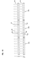
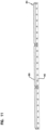
- Figures 31 and 32 show another surface excavation machine 720 suitable for using a reducing element wear sensing system of a type described herein.
- the surface excavation machine 720 includes reducing elements 742 carried by a chain 738.
- the chain 738 is driven by a gear 739.
- the rotational position of the chain can be identified by sensing reducing elements arranged in a non-repeating configuration along a given reducing path.
- a non-repeating configuration is a configuration that does not repeat over the course of one full rotation of the chain.
- the simplest non-repeating configuration is a single reducing element corresponding to one sensor and/or one reducing path.
- the controller can establish a position of the reducing element on the chain and can determine the rotational position of all the other reducing elements on the chain.
- Another example of a non-repeating pattern includes two reducing elements monitored on the same reducing path that are not uniformly spaced about the perimeter of the chain.
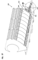
- FIGs 33 and 34 show another example of a wear sensing system 800 in accordance with the principles of the present disclosure.
- the wear sensing system 800 can include a multi-level wear sensor protection system 802.
- the wear sensor protection system 802 is configured to protect wear sensors 804 (see Figure 34 ) from damage under the most extreme conditions.
- the multi-level wear sensor protection system 802 is also configured to allow the wear sensors 804 to provide sensing functionality during milling operations.
- the wear sensing system 800 can provide continuous tooth wear monitoring without requiring interruptions in milling operations for assessing tooth wear.
- the multi-level wear sensor protection system 802 includes a first level of protection, a second level of protection, and a third level of protection. The first level of protection is illustrated and described in more detail in Figure 35 .
- the first level of protection can be in the form of an initial barrier layer 806 (e.g., initial shield layer).
- the initial barrier layer 806 surrounds the reducing drum (not shown) and is positioned between the reducing drum and the wear sensors 804.
- the initial barrier layer 806 curves at least partially around the reducing drum.
- the initial barrier layer 806 can have a radius of curvature centered on the axis of rotation of the reducing drum.
- the initial barrier layer 806 can have a sheet-like construction including a plurality of sheet segments 808 secured to the machine frame 810 in a side-by-side arrangement.
- the initial barrier layer 806 can include a material such as polycarbonate. In Figure 34 , the initial barrier layer 806 is shown with portions of the plurality of sheet segments 808 removed.
- the sheet segment 808 includes a main segment body 812 having an upper end 814 and a lower end 816.
- the upper and lower ends 814, 816 of the main segment body 812 can respectively be secured with upper and lower fittings 818, 820 (e.g., fixtures).
- the upper fitting 818 can include fastener openings 822 for receiving fasteners (not shown) used to secure the sheet segment 808 to the machine frame 810 (see Figure 33 ).
- the lower fittings 820 can each include a first tab 826 and a second tab 828 that fit within corresponding tab receptacles 830 (see Figure 34 ).
- the plurality of sheet segments 808 can include openings 807 (see Figure 36 ) at the upper and lower ends 814, 816 of the main segment body 812.
- the plurality of sheet segments 808 can be secured to the fittings 818, 820 using fastening bands 809 that include apertures (not shown) that align or correspond with the openings 807 of the plurality of sheet segments 808.
- the fastening bands 809 are attached to the plurality of sheet segments 808 using fasteners 811 (e.g., rivets, cap screw, pins, ties, adhesive, etc.) to secure the plurality of sheet segments 808 to the upper and lower fittings 818, 820 respectively.
- the initial barrier layer 806 can have a robust construction. In certain examples, the initial barrier layer 806 can be easily replaced and has a relatively low cost.
- each of the plurality of sheet segments 808 can be installed by sliding the sheet-like structure downwardly about the rotor along a guide track until the first and second tabs 826, 828 fit within the corresponding tab receptacles 830 secured to the machine frame 810. Thereafter, fasteners can be used to secure the upper ends 814 of the plurality of sheet segments 808 to the machine frame 810.
- the upper ends 814 of the plurality of sheet segments 808 are at a location that is easily accessed by an operator.
- the fasteners at the upper ends 814 of each of the plurality of sheet segments 808 are removed and the plurality of sheet segments 808 are slid upwardly to disengage the first and second tabs 826, 828 from the tab receptacles 830 and to slide the plurality of sheet segments 808 out from around the reducing component.
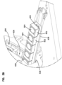
- the multi-level wear sensor protection system 802 can also include a second level of protection in the form of trays 832 (e.g., housings) 832 in which the wear sensors 804 are mounted.
- the trays 832 are mounted behind the initial barrier layer 806 and are configured to absorb impacts that are transmitted through the initial barrier layer 806 to prevent the impacts from impacting upon the wear sensors 804 contained within the trays 832.
- the trays 832 include a wear resistant material such as polycarbonate. The trays 832 help provide impact protection to the wear sensors 804 while concurrently allowing magnetic fields generated by the wear sensors 804 to pass through the trays 832.
- the second level of protection is illustrated and described in more detail in Figures 38-42 .
- FIG. 38 is an enlarged view of a portion of the second level of protection shown in Figure 37 .
- the trays 832 can be mounted together along a plate 834.
- the plate 834 can be arranged and configured to slide a plurality of the trays 832 and wear sensors 804 as a unit into channels 836. As depicted, the channels 836 are constructed to be parallel to one another.
- rails 838 can be attached to the plates 834.
- the rails 838 can have lengths that extend along the drum axis.
- the rails 838 can be secured (e.g., welded, coupled) to the plate 834 opposite to that of the trays 832.
- the plate 834 can be slid longitudinally into the channels 836 that extend along the drum axis.
- an array of trays 832 is depicted along the plate 834.
- the plate is shown attached to the rails 838.
- the plate 834 can be inserted in channels 836 from a right side of the machine. It will be appreciated that the plate 834 including the array of trays 832 can also be inserted into channels 836 from a left side of the machine.
- Figure 40 a side view of the array of trays 832 positioned along the plate 834 is shown.
- Figure 41 shows a cross-sectional view of the array of trays 832 shown in Figure 40 .
- the third level of protection includes an impact absorption structure 840 (e.g., relief structure) for accommodating impacts that are transmitted through both the initial barrier layer 806 (see Figure 37 ) and the trays 832.
- an impact absorption structure 840 e.g., relief structure
- electrical contacts and wiring 842 are shown on a back side of the wear sensor 804 (see Figure 39 ) for allowing the wear sensor 804 to be electrically connected to a control system having suitable control circuitry for controlling operation of the wear sensor 804.
- a metal plate 844 can be mounted to the impact absorption structure 840 adjacent to a back side of the wear sensor 804.
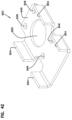
- the impact absorption structure 840 is illustrated and described in more detail in Figure 42 .
- the impact absorption structure 840 includes a base 846 that can be attached to the plate 834 (see Figure 41 ).
- the base 846 can define a plurality of apertures 848 for receiving fasteners (not shown) to couple the impact absorption structure 840 to the plate 834.
- the base 846 of the impact absorption structure 840 can define a center opening 850.
- the center opening 850 can be configured to receive a grommet 852 (see Figure 41 ).
- the impact absorption structure 840 can be arranged and configured to bend and flex about legs 854 upon impact.
- Figure 44 is an enlarged view of a portion of Figure 43 .
- the impact absorption structure 840 e.g., relief structure
- the impact absorption structure 840 can be positioned behind the trays 832 to help accommodate movement of the trays 832 in response to an impact that passes through the initial barrier layer 806 (see Figure 37 ) and upon the trays 832.
- the legs 854 of the impact absorption structure 840 are configured to bend upon impact.
- the impact absorption structure 840 can include a structure that in-elastically deforms in response to an impact. In such situations, the impact absorption structure 840 will remain bent upon impact. It will be appreciated that such structures would likely require fixing or replacement more often than a resilient structure.
- the impact absorption structure 840 can be made of a plastic material for providing flexibility upon impact such that the impact absorption structure 840 does not remain bent upon impact.
- the impact absorption structure 840 can include an elastic /resilient structure that biases the trays 832 toward a sensing position and allows the trays 832 to move away from a reducing component in response to an impact. After impact, such resilient impact absorption structures 840 can bias the impacted trays 832 back toward their corresponding sensing positions.
- the third level of protection is illustrated and described in more detail in Figures 44-48 .
- the legs 854 of the impact absorption structure 840 can be coupled to the trays 832 to secure the trays 832 along the plate 834.
- the plate 834 having the impact absorption structure 840 mounted thereon is shown positioned within the channel 836.
- FIG. 45 a bottom view of the multi-layer wear sensor protection system 802 is shown. Details of the construction of the multi-layer wear sensor protection system is illustrated and described in more detail in Figure 46 .
- FIG 46 an enlarged view of a portion of Figure 45 is shown.
- the construction of the multi-level wear sensor protection system 802 allows for a unit of trays 832 secured to the impact absorption structure 840 to be inserted into the channels 836 from either a left or right side of the machine by the plate 834.
- the plate 834 can slide into the channels 836 on top of ledges 856.
- the ledges 856 can be welded to elongated members 858 that extend longitudinally along the drum axis.
- the rails 838 located within the channels 836 can receive wedges 860.
- Figure 48 is a cross-sectional view of the multi-layer wear sensor protection system 802 illustrating the array of trays 832 in the channel 836 along the drum axis.
- Figure 49 is an enlarged view of a portion of Figure 48 .
- the wedges 860 can include a tapered end 862.
- the wedges 860 can be inserted along the rails 838 (see Figure 46 ) from the left and/or right sides of the machine.
- the rails 838 can guide the wedges 860 during insertion.
- the wedges 860 can be inserted such that the tapered end 862 of the wedges 860 engage a ramp surface 864 in a center portion of the channel 836 when fully inserted.
- the wedges 860 provide downward force to the plate 834 to clamp down on the trays 832 to provide stability and keep the plate 834 in place.
- the plates 834 are clamped against the ledges 856.
- the wedges 860 can be coupled to L-shaped brackets 866 to keep the wedges 860 in position.
- the wedges 860 can be bolted to the L-shaped brackets 866.
- the L-shaped bracket 866 can be attached to the main bracket 868 (see Figure 47 ) and can be moved relative to the main frame via fasteners to control the position of the outer ends (i.e., the non-tapered ends) of the wedges 860 to ensure the plate 834 is firmly clamped against the ledges/shoulders 856 of the channels 836 along its entire length.
Landscapes
- Engineering & Computer Science (AREA)
- Mining & Mineral Resources (AREA)
- Civil Engineering (AREA)
- Structural Engineering (AREA)
- Mechanical Engineering (AREA)
- General Engineering & Computer Science (AREA)
- Life Sciences & Earth Sciences (AREA)
- Geology (AREA)
- Architecture (AREA)
- Geochemistry & Mineralogy (AREA)
- General Life Sciences & Earth Sciences (AREA)
- Physics & Mathematics (AREA)
- Environmental & Geological Engineering (AREA)
- Fluid Mechanics (AREA)
- Earth Drilling (AREA)
- Excavating Of Shafts Or Tunnels (AREA)
- Analytical Chemistry (AREA)
- Chemical & Material Sciences (AREA)
- Biochemistry (AREA)
- General Health & Medical Sciences (AREA)
- General Physics & Mathematics (AREA)
- Immunology (AREA)
- Pathology (AREA)
- Health & Medical Sciences (AREA)
- Percussive Tools And Related Accessories (AREA)
- Constituent Portions Of Griding Lathes, Driving, Sensing And Control (AREA)
- Geophysics And Detection Of Objects (AREA)
- Crushing And Grinding (AREA)
Applications Claiming Priority (3)
| Application Number | Priority Date | Filing Date | Title |
|---|---|---|---|
| US201261736303P | 2012-12-12 | 2012-12-12 | |
| PCT/US2013/074672 WO2014093625A1 (fr) | 2012-12-12 | 2013-12-12 | Systèmes et procédés pour détecter une usure d'éléments de broyage d'une machine de broyage de matériau |
| EP13862946.4A EP2931980B1 (fr) | 2012-12-12 | 2013-12-12 | Systèmes et procédés pour détecter une usure d'éléments de broyage d'une machine de broyage de matériau |
Related Parent Applications (2)
| Application Number | Title | Priority Date | Filing Date |
|---|---|---|---|
| EP13862946.4A Division EP2931980B1 (fr) | 2012-12-12 | 2013-12-12 | Systèmes et procédés pour détecter une usure d'éléments de broyage d'une machine de broyage de matériau |
| EP13862946.4A Division-Into EP2931980B1 (fr) | 2012-12-12 | 2013-12-12 | Systèmes et procédés pour détecter une usure d'éléments de broyage d'une machine de broyage de matériau |
Publications (2)
| Publication Number | Publication Date |
|---|---|
| EP4484919A2 true EP4484919A2 (fr) | 2025-01-01 |
| EP4484919A3 EP4484919A3 (fr) | 2025-04-09 |
Family
ID=50934951
Family Applications (2)
| Application Number | Title | Priority Date | Filing Date |
|---|---|---|---|
| EP24205181.1A Pending EP4484919A3 (fr) | 2012-12-12 | 2013-12-12 | Systèmes et procédés de détection d'usure d'éléments de réduction d'une machine de réduction de matériau |
| EP13862946.4A Active EP2931980B1 (fr) | 2012-12-12 | 2013-12-12 | Systèmes et procédés pour détecter une usure d'éléments de broyage d'une machine de broyage de matériau |
Family Applications After (1)
| Application Number | Title | Priority Date | Filing Date |
|---|---|---|---|
| EP13862946.4A Active EP2931980B1 (fr) | 2012-12-12 | 2013-12-12 | Systèmes et procédés pour détecter une usure d'éléments de broyage d'une machine de broyage de matériau |
Country Status (7)
| Country | Link |
|---|---|
| US (3) | US9890504B2 (fr) |
| EP (2) | EP4484919A3 (fr) |
| CN (1) | CN104981570B (fr) |
| AU (2) | AU2013359202B2 (fr) |
| ES (1) | ES3008697T3 (fr) |
| RU (1) | RU2645056C2 (fr) |
| WO (1) | WO2014093625A1 (fr) |
Families Citing this family (33)
| Publication number | Priority date | Publication date | Assignee | Title |
|---|---|---|---|---|
| AU2013359202B2 (en) * | 2012-12-12 | 2018-05-10 | Vermeer Manufacturing Company | Systems and methods for sensing wear of reducing elements of a material reducing machine |
| DE102013010866A1 (de) * | 2013-06-28 | 2014-12-31 | Bomag Gmbh | Bodenfräsmaschine mit einer Sensoreinrichtung zur berührungslosen Bestimmung von Verschleiß an Meißeleinrichtungen und Verfahren zur berührungslosen Bestimmung von Verschleiß an Meißeleinrichtungen einer Bodenfräsmaschine |
| AU2014262221C1 (en) | 2013-11-25 | 2021-06-10 | Esco Group Llc | Wear part monitoring |
| RU2681173C2 (ru) | 2014-02-19 | 2019-03-04 | Вермеер Мануфакчеринг Компани | Система и способ контроля степени износа измельчающих элементов |
| CN111441401B (zh) * | 2014-12-16 | 2022-06-07 | 住友建机株式会社 | 挖土机 |
| CA2976374C (fr) | 2015-02-13 | 2023-08-01 | Esco Corporation | Surveillance de produits d'attaque du sol destines a un equipement de terrassement |
| WO2016137363A1 (fr) * | 2015-02-23 | 2016-09-01 | Husqvarna Ab | Engin de creusement de tranchées |
| US20160258119A1 (en) * | 2015-03-03 | 2016-09-08 | Caterpillar Inc. | Automatic Rotor Speed Control |
| KR102488448B1 (ko) | 2015-03-27 | 2023-01-12 | 스미토모 겐키 가부시키가이샤 | 쇼벨 |
| CA3263786A1 (en) * | 2015-11-12 | 2025-03-24 | Joy Global Surface Mining Inc | Methods and systems for detecting heavy machine wear |
| CN105507356A (zh) * | 2016-02-01 | 2016-04-20 | 徐州徐工基础工程机械有限公司 | 一种双轮铣槽机铣削轮用摆齿机构 |
| RU2654927C1 (ru) * | 2016-12-02 | 2018-05-23 | Государственное образовательное учреждение высшего профессионального образования Кыргызско-Российский Славянский университет (КРСУ) | Устройство для разрушения горных пород |
| US10385688B2 (en) | 2016-12-21 | 2019-08-20 | Caterpillar Paving Products Inc. | Wear monitoring system for milling drum |
| CA3057384C (fr) * | 2017-04-12 | 2021-05-25 | Roadtec, Inc. | Systeme de suivi du temps de fonctionnement d'un convoyeur d'engin de chantier |
| IT201700082167A1 (it) * | 2017-07-19 | 2019-01-19 | Matermacc S P A | Dispositivo distributore di materiale per macchine agricole |
| DE102017118914B4 (de) * | 2017-08-18 | 2023-09-21 | Flsmidth A/S | System und Verfahren zur Bestimmung des Verschleißes abtragender Elemente an einem Schaufelradgerät |
| EA035202B1 (ru) * | 2017-10-06 | 2020-05-15 | Кыргызско-Российский Славянский Университет | Устройство для разрушения горных пород |
| US10533306B2 (en) * | 2017-11-01 | 2020-01-14 | Deere & Company | Joint wear device for a work vehicle |
| CN108035392B (zh) * | 2017-12-05 | 2020-08-14 | 浙江吉通地空建筑科技有限公司 | 渠式切割水泥土连续墙切割设备的链锯坠落止挡装置 |
| DE102018115959A1 (de) | 2018-07-02 | 2020-01-02 | Wirtgen Gmbh | Verschleißbauteil einer Fräsmaschine, Fräsmaschine und Verfahren zur Bestimmung des Verschleißes des Verschleißbauteils |
| US11549797B2 (en) * | 2018-10-26 | 2023-01-10 | Deere & Company | Device for detecting wear of replaceable components |
| CN215825216U (zh) * | 2018-12-11 | 2022-02-15 | 米沃奇电动工具公司 | 电动工具以及用于电动工具的冲击机构的锤 |
| CN109457747B (zh) * | 2018-12-12 | 2023-09-01 | 江苏徐工工程机械研究院有限公司 | 一种双轮铣槽机多层钢丝绳卷扬自动标定装置 |
| WO2020205460A1 (fr) * | 2019-04-01 | 2020-10-08 | Schlumberger Technology Corporation | Dispositif de coupe instrumenté |
| US11686067B2 (en) * | 2019-05-15 | 2023-06-27 | Deere & Company | Motor grader cutting edge wear calibration and warning system |
| US11542938B2 (en) * | 2019-10-18 | 2023-01-03 | Bode Intelligence Technology Co., Ltd. | Polished rod rotation sensor |
| US11591758B2 (en) * | 2019-12-10 | 2023-02-28 | Caterpillar Paving Products Inc. | Work machines and systems for monitoring wear of components of work machines |
| CN111289569A (zh) * | 2020-03-25 | 2020-06-16 | 上海道基环保科技有限公司 | 一种路面破碎用刀具磨损监控装置及其方法 |
| CN111678765B (zh) * | 2020-06-02 | 2023-11-07 | 湖北工程学院 | 一种载流摩擦磨损试验机、试验系统及其试验方法 |
| CA3207314A1 (fr) * | 2021-02-12 | 2022-08-18 | Metalogenia Research & Technologies S.L. | Ensemble d'usure pour une machine de deplacement de terre et machine correspondante |
| GB202109006D0 (en) * | 2021-06-23 | 2021-08-04 | Anglo American Minerio De Ferro Brasil S/A | Method of and system for operating a grinding mill |
| CN115060565B (zh) * | 2022-08-16 | 2022-11-01 | 昆明理工大学 | 一种用于预裂爆破模型试验的检测设备及方法 |
| WO2025074336A1 (fr) * | 2023-10-04 | 2025-04-10 | Flsmidth A/S | Appareil et procédé de détection d'usure pour dispositifs de broyage |
Citations (3)
| Publication number | Priority date | Publication date | Assignee | Title |
|---|---|---|---|---|
| DE10015005A1 (de) | 2000-03-20 | 2001-10-18 | Georg Wendland | Einrichtung zur Online-Messung des Werkzeugverschleisses beim Spanen von abrasiven Materialien |
| US7290360B2 (en) | 2005-09-26 | 2007-11-06 | Vermeer Manufacturing Company | Excavation apparatus |
| US20100076697A1 (en) | 2008-09-03 | 2010-03-25 | Stefen Wagner | Method for determining the wear state |
Family Cites Families (58)
| Publication number | Priority date | Publication date | Assignee | Title |
|---|---|---|---|---|
| SE361704B (fr) | 1971-09-07 | 1973-11-12 | Atlas Copco Ab | |
| GB1407236A (en) | 1972-10-10 | 1975-09-24 | Coal Industry Patents Ltd | Cutting force sensor |
| FR2252892A1 (fr) * | 1973-12-04 | 1975-06-27 | Renault | |
| US4006936A (en) | 1975-11-06 | 1977-02-08 | Dresser Industries, Inc. | Rotary cutter for a road planer |
| US4176396A (en) | 1977-09-23 | 1979-11-27 | The Charles Stark Draper Laboratory, Inc. | Apparatus for directly measuring machine tool wear |
| EP0083047B1 (fr) * | 1981-12-24 | 1987-02-04 | Bayerische Motoren Werke Aktiengesellschaft, Patentabteilung AJ-3 | Procédé de contrôle des pièces mécaniques et dispositif pour sa mise en oeuvre |
| DE3218754C2 (de) | 1982-05-18 | 1985-11-28 | Friedrich Deckel AG, 8000 München | Verfahren und Einrichtung zur Vermessung eines in einem zustellbaren Werkzeughalter einer Werkzeugmaschine eingespannten Werkzeugs |
| DE3248768A1 (de) | 1982-12-31 | 1984-07-05 | Bergwerksverband Gmbh, 4300 Essen | Mess- und bestueckungsgeraet fuer schneidkoepfe und schneidwalzen |
| DE3411892C2 (de) | 1984-03-30 | 1986-06-19 | Oerlikon-Boehringer GmbH, 7320 Göppingen | Vorrichtung zum Messen des Verschleißes der Werkzeuge einer Fräsmaschine |
| US4637753A (en) | 1984-11-19 | 1987-01-20 | Cmi Corporation | Road planar having particle reducing means |
| DE3505408A1 (de) | 1985-02-16 | 1986-08-21 | Gebr. Eickhoff Maschinenfabrik U. Eisengiesserei Mbh, 4630 Bochum | Verfahren zum feststellen des verschleisses von schraemmeisseln einer schraemwalze |
| AT382683B (de) | 1985-08-16 | 1987-03-25 | Voest Alpine Ag | Einrichtung zur ueberwachung des abnuetzungsgrades von meisseln eines schraemkopfes |
| DE3643309C1 (de) | 1986-12-18 | 1988-03-10 | Bergwerksverband Gmbh | Vorrichtung zur Ermittlung des Ringzahnverschleisses an Rollenbohrwerkzeugen |
| FR2611767B1 (fr) * | 1987-03-03 | 1989-06-30 | Beugnet Sa | Atelier de regeneration d'une chaussee |
| US4845763A (en) | 1987-11-06 | 1989-07-04 | General Motors Corporation | Tool wear measurement by machine vision |
| DE3818213A1 (de) | 1988-05-28 | 1989-11-30 | Gewerk Eisenhuette Westfalia | Meissel, insbesondere fuer bergbau-gewinnungsmaschinen, vortriebsmaschinen u. dgl. |
| DE4107678A1 (de) | 1991-03-09 | 1992-09-10 | Bergwerksverband Gmbh | Vorrichtung zur ermittlung verschiedener kenndaten beim betrieb von rollenbohrwerkzeugen |
| DE4222085A1 (de) | 1992-07-04 | 1994-01-05 | Kloeckner Humboldt Deutz Ag | Verschleißmeßverfahren für Mahlwalzen von Walzenmaschinen |
| JP3184432B2 (ja) | 1995-07-28 | 2001-07-09 | 株式会社奥村組 | ローラビットの摩耗検知装置 |
| JPH09168944A (ja) * | 1995-12-20 | 1997-06-30 | Komatsu Ltd | ターンブローチの異常検出装置 |
| JPH10266783A (ja) | 1997-03-28 | 1998-10-06 | Komatsu Ltd | ディスクカッタの摩耗検出方法および摩耗検出装置 |
| AT2938U1 (de) * | 1997-04-02 | 1999-07-26 | Schmid & Schneiber Planungs Un | Fräsbrecherfahrzeug |
| JPH10311717A (ja) * | 1997-05-09 | 1998-11-24 | Fujita Corp | トンネル掘削機械のローラビット摩耗検出装置 |
| SE525078C2 (sv) | 2001-06-29 | 2004-11-23 | Abb Ab | Metod samt induktiv mätanordning för detektering av mittpunkten hos ett elektriskt ledande material |
| US7144087B2 (en) | 2002-01-09 | 2006-12-05 | Asph{dot over (a)}lt Zipper, Inc. | Systems and methods for milling paving material with increased stability, support, and power |
| DE10203732A1 (de) * | 2002-01-30 | 2003-08-21 | Wirtgen Gmbh | Baumaschine |
| US6769836B2 (en) | 2002-04-11 | 2004-08-03 | Enviro-Pave, Inc. | Hot-in-place asphalt recycling machine and process |
| JP3919172B2 (ja) | 2002-04-17 | 2007-05-23 | 株式会社スターロイ | ディスクローラーカッター及びディスクローラーカッターモニタリングシステム |
| EP1367176A1 (fr) | 2002-05-22 | 2003-12-03 | BITELLI S.p.A. | Système anti-poussière pour machine de construction de chaussées |
| US7205166B2 (en) * | 2002-06-28 | 2007-04-17 | Lam Research Corporation | Method and apparatus of arrayed, clustered or coupled eddy current sensor configuration for measuring conductive film properties |
| US7066555B2 (en) | 2003-08-26 | 2006-06-27 | Asphalt Zipper, Inc. | Reinforced concrete milling/cutting mandrel |
| US6990390B2 (en) | 2004-05-19 | 2006-01-24 | Caterpillar Inc. | Method and apparatus to detect change in work tool |
| US7223049B2 (en) * | 2005-03-01 | 2007-05-29 | Hall David R | Apparatus, system and method for directional degradation of a paved surface |
| DE102005016346B3 (de) | 2005-04-09 | 2007-01-04 | Hochtief Construction Ag | Diskenmeißel-Verschleißmessvorrichtung und Verfahren zur Messung eines Diskenmeißelverschleißes |
| CN101248330B (zh) | 2005-06-28 | 2015-06-17 | 斯甘拉伊斯股份有限公司 | 相对于参考测量和绘制表面的系统和方法 |
| US20110121633A1 (en) * | 2006-02-10 | 2011-05-26 | Hall David R | Billing System Integrated into a Milling Machine |
| CA2654551A1 (fr) | 2006-08-07 | 2008-02-21 | Me Global Inc. | Utilisation de donnees historiques pour estimer des profils d'usure de produits d'usure consommables |
| US20080153402A1 (en) | 2006-12-20 | 2008-06-26 | Christopher Arcona | Roadway grinding/cutting apparatus and monitoring system |
| PE20080048A1 (es) | 2006-12-20 | 2008-02-25 | Scanalyse Pty Ltd | Sistema para la medicion del desplazamiento de una superficie relativa a una base de referencia |
| US8465105B2 (en) | 2007-01-18 | 2013-06-18 | Cmi Terex Corporation | Control system for cutter drum |
| US9222239B2 (en) * | 2007-09-11 | 2015-12-29 | Vermeer Manufacturing Company | On-board service tool and method |
| DE102007044090A1 (de) | 2007-09-14 | 2009-04-09 | Wirtgen Gmbh | Straßenfräsmaschine oder Maschine zur Ausbeutung von Lagerstätten |
| SE532815C2 (sv) | 2007-11-09 | 2010-04-13 | Combi Wear Parts Ab | Självskärpande, autosignalerande slitdel |
| JP5377860B2 (ja) * | 2008-01-16 | 2013-12-25 | キャタピラー エス エー アール エル | 作業機械の角度センサ取付構造 |
| CN101525887A (zh) * | 2008-03-03 | 2009-09-09 | 王俊斗 | 高效节能型滚动式多功能挖掘机 |
| AU2013100451B4 (en) | 2008-09-03 | 2013-09-19 | Wirtgen Gmbh | Method for determining the wear state |
| US8061782B2 (en) | 2008-09-12 | 2011-11-22 | Hall David R | Sensors on a degradation machine |
| US8122798B1 (en) | 2008-11-19 | 2012-02-28 | Power Tool Institute | Power cutting tool with proximity sensing system |
| US8006781B2 (en) | 2008-12-04 | 2011-08-30 | Baker Hughes Incorporated | Method of monitoring wear of rock bit cutters |
| US8183491B2 (en) * | 2009-05-26 | 2012-05-22 | General Electric Company | Electric discharge machining device using rotating circular blade |
| US20120217357A1 (en) | 2009-09-09 | 2012-08-30 | Jochen Franke | System and method for monitoring condition of surface subject to wear |
| US8128177B2 (en) * | 2010-02-08 | 2012-03-06 | Wirtgen Gmbh | Adaptive advance drive control for milling machine |
| DE102011016271A1 (de) * | 2011-04-06 | 2012-10-11 | Wirtgen Gmbh | Walzengehäuse für eine Arbeitswalze einer Baumaschine oder Abbaumaschine, Baumaschine oder Abbaumaschine, sowie Verfahren zum Überwachen des Zustandes einer Arbeitswalze einer Baumaschine oder Abbaumaschine |
| TWI515129B (zh) | 2011-04-11 | 2016-01-01 | 群邁通訊股份有限公司 | 汽車控制系統及方法 |
| US20130234494A1 (en) * | 2012-03-07 | 2013-09-12 | David R. Hall | Sensors on a Degradation Platform |
| DE102012216262B3 (de) * | 2012-09-13 | 2013-10-17 | Wirtgen Gmbh | Walzengehäuse für eine Arbeitswalze einer Baumaschine oder Abbaumaschine, Baumaschine oder Abbaumaschine, sowie Verfahren zum Überwachen des Zustandes einer Arbeitswalze einer Baumaschine oder Abbaumaschine |
| AU2013359202B2 (en) * | 2012-12-12 | 2018-05-10 | Vermeer Manufacturing Company | Systems and methods for sensing wear of reducing elements of a material reducing machine |
| DE102013010866A1 (de) * | 2013-06-28 | 2014-12-31 | Bomag Gmbh | Bodenfräsmaschine mit einer Sensoreinrichtung zur berührungslosen Bestimmung von Verschleiß an Meißeleinrichtungen und Verfahren zur berührungslosen Bestimmung von Verschleiß an Meißeleinrichtungen einer Bodenfräsmaschine |
-
2013
- 2013-12-12 AU AU2013359202A patent/AU2013359202B2/en active Active
- 2013-12-12 CN CN201380072713.2A patent/CN104981570B/zh active Active
- 2013-12-12 EP EP24205181.1A patent/EP4484919A3/fr active Pending
- 2013-12-12 EP EP13862946.4A patent/EP2931980B1/fr active Active
- 2013-12-12 WO PCT/US2013/074672 patent/WO2014093625A1/fr not_active Ceased
- 2013-12-12 RU RU2015123824A patent/RU2645056C2/ru active
- 2013-12-12 US US14/651,951 patent/US9890504B2/en active Active
- 2013-12-12 ES ES13862946T patent/ES3008697T3/es active Active
-
2018
- 2018-02-12 US US15/894,314 patent/US10415195B2/en active Active
- 2018-08-03 AU AU2018211332A patent/AU2018211332B2/en not_active Expired - Fee Related
-
2019
- 2019-07-31 US US16/527,672 patent/US10947678B2/en active Active
Patent Citations (3)
| Publication number | Priority date | Publication date | Assignee | Title |
|---|---|---|---|---|
| DE10015005A1 (de) | 2000-03-20 | 2001-10-18 | Georg Wendland | Einrichtung zur Online-Messung des Werkzeugverschleisses beim Spanen von abrasiven Materialien |
| US7290360B2 (en) | 2005-09-26 | 2007-11-06 | Vermeer Manufacturing Company | Excavation apparatus |
| US20100076697A1 (en) | 2008-09-03 | 2010-03-25 | Stefen Wagner | Method for determining the wear state |
Also Published As
| Publication number | Publication date |
|---|---|
| CN104981570A (zh) | 2015-10-14 |
| WO2014093625A1 (fr) | 2014-06-19 |
| AU2013359202B2 (en) | 2018-05-10 |
| AU2013359202A1 (en) | 2015-07-02 |
| US20150322634A1 (en) | 2015-11-12 |
| US9890504B2 (en) | 2018-02-13 |
| AU2018211332B2 (en) | 2020-09-03 |
| RU2015123824A (ru) | 2017-01-19 |
| AU2018211332A1 (en) | 2018-08-23 |
| EP2931980A4 (fr) | 2016-08-31 |
| EP2931980A1 (fr) | 2015-10-21 |
| EP4484919A3 (fr) | 2025-04-09 |
| US20180163352A1 (en) | 2018-06-14 |
| ES3008697T3 (en) | 2025-03-24 |
| CN104981570B (zh) | 2017-10-03 |
| RU2645056C2 (ru) | 2018-02-15 |
| EP2931980B1 (fr) | 2024-11-13 |
| US10947678B2 (en) | 2021-03-16 |
| US20190352866A1 (en) | 2019-11-21 |
| US10415195B2 (en) | 2019-09-17 |
Similar Documents
| Publication | Publication Date | Title |
|---|---|---|
| US10947678B2 (en) | Systems and methods for sensing wear of reducing elements of a material reducing machine | |
| EP3108071B1 (fr) | Procédé pour surveiller l'usure d'éléments de réduction d'une machine d'excavation | |
| EP3234266B1 (fr) | Dispositif de détection d'usure comportant un boîtier | |
| JP2019163689A (ja) | 摩耗部品の監視 | |
| AU2011201227B8 (en) | Blade segment and blade assembly for a surface working vehicle | |
| US20130082846A1 (en) | Sensor system and method | |
| Rusiński et al. | Investigation and modernization of buckets of surface mining machines | |
| EP3175050B1 (fr) | Element d'usure de tranchant d'accessoire | |
| WO2015017894A1 (fr) | Blindage résistant à l'usure pour ensemble de machines d'exploitation minière | |
| JP6238432B2 (ja) | シールド掘進機のカッタ盤およびそれを備えるシールド掘進機 | |
| EP3175047B1 (fr) | Élément d'usure d'outil ayant un indicateur d'usure | |
| US6132005A (en) | Detecting seam boundary using pick sound | |
| KR102553609B1 (ko) | 경암용 tbm 커팅툴 스마트 마모감지 시스템 및 경암용 tbm 커팅툴 스마트 마모감지 방법 | |
| US20150345290A1 (en) | Surface mining tooth retention | |
| JP7761665B2 (ja) | トンネル掘進機用の切削ホイール | |
| AU723275B2 (en) | Detecting a boundary between two layers of material | |
| Bristow | Mechanical Equipment Safety |
Legal Events
| Date | Code | Title | Description |
|---|---|---|---|
| PUAI | Public reference made under article 153(3) epc to a published international application that has entered the european phase |
Free format text: ORIGINAL CODE: 0009012 |
|
| STAA | Information on the status of an ep patent application or granted ep patent |
Free format text: STATUS: THE APPLICATION HAS BEEN PUBLISHED |
|
| AC | Divisional application: reference to earlier application |
Ref document number: 2931980 Country of ref document: EP Kind code of ref document: P |
|
| AK | Designated contracting states |
Kind code of ref document: A2 Designated state(s): AL AT BE BG CH CY CZ DE DK EE ES FI FR GB GR HR HU IE IS IT LI LT LU LV MC MK MT NL NO PL PT RO RS SE SI SK SM TR |
|
| REG | Reference to a national code |
Ref country code: DE Ref legal event code: R079 Free format text: PREVIOUS MAIN CLASS: G01N0003560000 Ipc: E02F0003180000 |
|
| PUAL | Search report despatched |
Free format text: ORIGINAL CODE: 0009013 |
|
| AK | Designated contracting states |
Kind code of ref document: A3 Designated state(s): AL AT BE BG CH CY CZ DE DK EE ES FI FR GB GR HR HU IE IS IT LI LT LU LV MC MK MT NL NO PL PT RO RS SE SI SK SM TR |
|
| RIC1 | Information provided on ipc code assigned before grant |
Ipc: G01N 3/56 20060101ALI20250303BHEP Ipc: E21B 12/02 20060101ALI20250303BHEP Ipc: E02F 5/08 20060101ALI20250303BHEP Ipc: E21C 35/00 20060101ALI20250303BHEP Ipc: E21C 27/24 20060101ALI20250303BHEP Ipc: E21B 3/00 20060101ALI20250303BHEP Ipc: E01C 23/12 20060101ALI20250303BHEP Ipc: E02F 5/14 20060101ALI20250303BHEP Ipc: E02F 5/12 20060101ALI20250303BHEP Ipc: E01C 23/088 20060101ALI20250303BHEP Ipc: E02F 3/20 20060101ALI20250303BHEP Ipc: E02F 9/28 20060101ALI20250303BHEP Ipc: E02F 9/26 20060101ALI20250303BHEP Ipc: E02F 3/18 20060101AFI20250303BHEP |
|
| STAA | Information on the status of an ep patent application or granted ep patent |
Free format text: STATUS: REQUEST FOR EXAMINATION WAS MADE |
|
| 17P | Request for examination filed |
Effective date: 20250929 |
|
| GRAP | Despatch of communication of intention to grant a patent |
Free format text: ORIGINAL CODE: EPIDOSNIGR1 |
|
| STAA | Information on the status of an ep patent application or granted ep patent |
Free format text: STATUS: GRANT OF PATENT IS INTENDED |
|
| RIC1 | Information provided on ipc code assigned before grant |
Ipc: E02F 3/18 20060101AFI20260209BHEP Ipc: E02F 9/26 20060101ALI20260209BHEP Ipc: E02F 9/28 20060101ALI20260209BHEP Ipc: E02F 3/20 20060101ALI20260209BHEP Ipc: E01C 23/088 20060101ALI20260209BHEP Ipc: E02F 5/12 20060101ALI20260209BHEP Ipc: E02F 5/14 20060101ALI20260209BHEP Ipc: E01C 23/12 20060101ALI20260209BHEP Ipc: E21B 3/00 20060101ALI20260209BHEP Ipc: E21C 27/24 20060101ALI20260209BHEP Ipc: E21C 35/00 20060101ALI20260209BHEP Ipc: E02F 5/08 20060101ALI20260209BHEP Ipc: E21B 12/02 20060101ALI20260209BHEP Ipc: G01N 3/56 20060101ALI20260209BHEP |
|
| INTG | Intention to grant announced |
Effective date: 20260218 |