EP4485072A1 - Mustergenerator und verfahren zur ansteuerung eines mustergenerators - Google Patents
Mustergenerator und verfahren zur ansteuerung eines mustergenerators Download PDFInfo
- Publication number
- EP4485072A1 EP4485072A1 EP23182592.8A EP23182592A EP4485072A1 EP 4485072 A1 EP4485072 A1 EP 4485072A1 EP 23182592 A EP23182592 A EP 23182592A EP 4485072 A1 EP4485072 A1 EP 4485072A1
- Authority
- EP
- European Patent Office
- Prior art keywords
- laser illumination
- pattern
- sweep direction
- writing plane
- controlling
- Prior art date
- Legal status (The legal status is an assumption and is not a legal conclusion. Google has not performed a legal analysis and makes no representation as to the accuracy of the status listed.)
- Withdrawn
Links
Images



Classifications
-
- G—PHYSICS
- G03—PHOTOGRAPHY; CINEMATOGRAPHY; ANALOGOUS TECHNIQUES USING WAVES OTHER THAN OPTICAL WAVES; ELECTROGRAPHY; HOLOGRAPHY
- G03F—PHOTOMECHANICAL PRODUCTION OF TEXTURED OR PATTERNED SURFACES, e.g. FOR PRINTING, FOR PROCESSING OF SEMICONDUCTOR DEVICES; MATERIALS THEREFOR; ORIGINALS THEREFOR; APPARATUS SPECIALLY ADAPTED THEREFOR
- G03F7/00—Photomechanical, e.g. photolithographic, production of textured or patterned surfaces, e.g. printing surfaces; Materials therefor, e.g. comprising photoresists; Apparatus specially adapted therefor
- G03F7/70—Microphotolithographic exposure; Apparatus therefor
- G03F7/70216—Mask projection systems
- G03F7/70283—Mask effects on the imaging process
- G03F7/70291—Addressable masks, e.g. spatial light modulators [SLMs], digital micro-mirror devices [DMDs] or liquid crystal display [LCD] patterning devices
-
- G—PHYSICS
- G03—PHOTOGRAPHY; CINEMATOGRAPHY; ANALOGOUS TECHNIQUES USING WAVES OTHER THAN OPTICAL WAVES; ELECTROGRAPHY; HOLOGRAPHY
- G03F—PHOTOMECHANICAL PRODUCTION OF TEXTURED OR PATTERNED SURFACES, e.g. FOR PRINTING, FOR PROCESSING OF SEMICONDUCTOR DEVICES; MATERIALS THEREFOR; ORIGINALS THEREFOR; APPARATUS SPECIALLY ADAPTED THEREFOR
- G03F7/00—Photomechanical, e.g. photolithographic, production of textured or patterned surfaces, e.g. printing surfaces; Materials therefor, e.g. comprising photoresists; Apparatus specially adapted therefor
- G03F7/70—Microphotolithographic exposure; Apparatus therefor
- G03F7/70008—Production of exposure light, i.e. light sources
- G03F7/70025—Production of exposure light, i.e. light sources by lasers
-
- G—PHYSICS
- G03—PHOTOGRAPHY; CINEMATOGRAPHY; ANALOGOUS TECHNIQUES USING WAVES OTHER THAN OPTICAL WAVES; ELECTROGRAPHY; HOLOGRAPHY
- G03F—PHOTOMECHANICAL PRODUCTION OF TEXTURED OR PATTERNED SURFACES, e.g. FOR PRINTING, FOR PROCESSING OF SEMICONDUCTOR DEVICES; MATERIALS THEREFOR; ORIGINALS THEREFOR; APPARATUS SPECIALLY ADAPTED THEREFOR
- G03F7/00—Photomechanical, e.g. photolithographic, production of textured or patterned surfaces, e.g. printing surfaces; Materials therefor, e.g. comprising photoresists; Apparatus specially adapted therefor
- G03F7/70—Microphotolithographic exposure; Apparatus therefor
- G03F7/70008—Production of exposure light, i.e. light sources
- G03F7/70041—Production of exposure light, i.e. light sources by pulsed sources, e.g. multiplexing, pulse duration, interval control or intensity control
Definitions
- the present technology refers in general to pattern generators and in particular to pulsed pattern generators and methods for driving pulsed pattern generators.
- Pattern generators are today used for many types of purposes. Pattern generators used in lithography systems or photomask lithography systems are required to present very accurate printing properties.
- One approach to obtain high-quality pattern printing is to use Spatial Light Modulators (SLM), e.g. Digital Micromirror Devices (DMD), Liquid Crystal Displays (LCD), Grating Light Valves (GLV), Planar Light Valves (PLV), Micro Shutter Arrays (MSA), Analogue Spatial Light Modulators (ASLM) and/or Liquid Crystal on Silicon (LCS).
- SLM Spatial Light Modulators
- DMD Digital Micromirror Devices
- LCD Liquid Crystal Displays
- GLV Grating Light Valves
- PV Planar Light Valves
- MSA Micro Shutter Arrays
- ASLM Analogue Spatial Light Modulators
- LCDS Liquid Crystal on Silicon
- the SLM has an array of individually controllable elements arranged for generating an array of imaged elements within an image area on a
- the translation velocity for a writing stage in the X direction is given by the modulator pixel rate times the pixel size divided by the number of pixels in the Y direction.
- a 2D SLM with 2048 * 4096 micromirrors (X/Y) and 1000 Hz refresh rate for a 1200 nm pixel size would require an X-velocity of ⁇ 2.4 m/s.
- a larger SLM, that is wider in the Y-direction, can be used to reduce this required X velocity.
- larger SLM might be more difficult or expensive to produce. It will also require larger dimensioned illumination optics as well as some parts of the projection optics, which also increase cost and complexity.
- a general object of the present technology is to allow for high write speed while keeping physical translation speed on a manageable level.
- a pattern generator comprises a pulsed laser light source, a spatial light modulator (SLM), a control module, an optical end system and a stage positioning device.
- the SLM is optically connected to the pulsed laser light source and is arranged for generating a laser illumination pattern.
- the control module is arranged for controlling the SLM to generate laser illumination patterns according to print data.
- the target stage is arranged to enabling holding of a target having a light-sensitive target surface.
- the optical end system is optically connected to the SLM, and is arranged for positioning the laser illumination pattern on a writing plane intended to coincide with the light-sensitive target surface.
- the stage positioning device is configured for mechanically changing a relative position between the SLM and the writing plane in a scan direction, parallel to the writing plane.
- the optical end system further comprises a strip switch.
- the strip switch is configured to optically move a position of the laser illumination pattern on the writing plane in a sweep direction, parallel to the writing plane but perpendicular to the scan direction.
- the control module is further arranged for controlling the SLM and the pulsed laser light source in dependence of the position caused by the strip switch to generate individual specimens of the laser illumination patterns at at least two predetermined positions in the sweep direction. A distance between the at least two predetermined positions in the sweep direction relative to a closest other predetermined position is less or equal to a width in the sweep direction of the laser illumination pattern on the writing plane.
- a method for operating a pattern generator comprises providing of print data representing a pattern to be generated. Pulsed laser light is supplied to a SLM. The spatial light module is controlled to generate laser illumination patterns according to the print data. A relative position between the SLM and the writing plane is mechanically changed in a scan direction, parallel to a writing plane. An optical end system is arranged for positioning the laser illumination pattern on the writing plane. A strip switch of the optical end system is controlled to optically move a position of the laser illumination pattern on the writing plane in a sweep direction. The sweep direction is parallel to the writing plane but perpendicular to the scan direction.
- the controlling of the spatial light module and the supplying of pulsed laser light is further performed in dependence of the controlling of the strip switch for controlling the SLM to generate individual specimens of the laser illumination patterns at at least two predetermined positions in the sweep direction, with a distance in the sweep direction relative to a closest other predetermined position being less or equal to a width in the sweep direction of the laser illumination pattern on the writing plane.
- One advantage with the proposed technology is that the full pixel-rate from high speed SLMs is possible to utilize in more writer designs. These solutions contribute to lower velocities in the X direction of the writing stage, less reaction forces and shorter acceleration distances, which in turn leads to a decrease in produced motor heat. The accuracy of the motion of the stage can also be improved. The solution is also scalable to cope with even higher pixel-rates from SLM equipment.
- FIG. 1 illustrates schematically a pattern generator 1 based on an SLM 20. Note that the figure only depicts the principles of the operation of the pattern generator 1 and the cooperation between its different parts, which means that details of the geometric positions and designs of the figure are not of importance.
- the SLM 20 is here illustrated as an array 3 of individually controllable elements 4, in this embodiment radiation reflecting elements.
- a pulsed laser light source 10 produces pulsed light 5 that impinges on the array 3 and will be reflected into a set of exposure beams 6 towards a target surface 44 of a target 42.
- the target surface 44 is typically supported by a target support 40.
- the SLM 20 and the pulsed laser light source 10 are controlled by a control module 30, synchronizing the light pulses with the settings of the SLM 20.
- the individual elements 4 of SLM 20 are thereby controllable to admit reflection or to suppress reflection separately for each light pulse.
- the control of the SLM 20 is based on print data that is stored on a memory 32 connected to the control module 30.
- the light leaving the active part of the SLM 20 is directed to the target surface 44 via an optical end system 50.
- the light forms an array 21 of imaged elements 22.
- the imaged elements 22 forms a laser illumination pattern 13 on an imaged area 14.
- the illumination of each individual imaged element 22 is thereby controlled by a respective element 4 of the SLM 20.
- This nominal scaling is a uniform scaling determined by different design parameters, such as different distances, and by ordinary optics. The arrangements for achieving such a nominal scaling are well-known by any person skilled in the art and are not further discussed.
- the SLM 20 can be configured in many different ways. The details of the operation of the SLM 20 are not of crucial importance for the present ideas, as long as the individual control of the elements 4 is provided and the SLM 20 gives rise to the array 21 of imaged elements 22 in the imaged area 14 on the target surface 44.
- the imaged area 14 can be moved. This may typically be performed by mechanically moving the SLM 20 relative the target support 40, by moving the target support 40, the SLM 20 or both. The movement is performed using a stage positioning device 60.
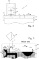
- Figure 2 is a schematic cross-section of the pattern generator 1.
- a stage positioning device 60 is configured for mechanically changing a relative position between the SLM 20 and the writing plane 43 in a scan direction 62, parallel to the writing plane 43.
- the SLM 22 When the full intended width, in the scan direction 62, has been illuminated, the SLM 22 returns to the start of the scan again, and a translation 63 of the target surface 44 relative to the SLM 20 is performed in a sweep direction 61, perpendicular to the scan direction 62.
- the sweep direction 61 is also referred to as the Y direction.
- a new scan can then begin.
- a height 47 of the imaged area 14 in the sweep direction may be equal to the translation 63, resulting in scans being positioned side-by-side.
- the translation 63 may be smaller than the height 47 of the imaged area 14, resulting in an overlap 64 of the scans.
- the required velocity for causing the appropriate relative movement between the SLM 20 and the target surface 44 may be awkwardly high.
- the velocity in the X-direction can be reduced.
- the imaged area resulting from the SLM needs to be shifted in the Y-direction in a time frame equal to the refresh rate of the SLM.
- the Y-shift can be achieved in several ways.
- the optical end system further comprises a strip switch.
- the strip switch is configured to optically move a position of the laser illumination pattern on the writing plane in a sweep direction, parallel to the writing plane but perpendicular to the scan direction.
- the control module is furthermore arranged for controlling the SLM and the pulsed laser light source in dependence of the position caused by the strip switch. This control is made to generate individual specimens of the laser illumination patterns at at least two predetermined positions in the sweep direction. A distance in the sweep direction relative to a closest other predetermined position is less or equal to a width, in the sweep direction, of the laser illumination pattern on the writing plane.
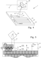
- a set of exposure beams 6 is provided to the optical end system 50.
- a strip switch 70 in this particular embodiment a microelectromechanical-system (MEMS) mirror 72, is arranged for switching the direction of the set of exposure beams 6 towards the target surface 44.
- the strip switch 70 is thus configured to optically move a position of the laser illumination pattern 13 on the writing plane 43 in a sweep direction 61, parallel to the writing plane 43 but perpendicular to the scan direction 62. In this way, a set of switched exposure beams 6' can be directed to either of two different strips 45 in the scan direction 62.
- MEMS microelectromechanical-system
- the dotted line 6 indicates a previous direction of the switched exposure beams, directed to the other strip 45 presently being printed.
- the basic idea is not limited to two strips 45, but can be applied also to more than two strips 45.
- the two strips 45 are displaced relative each other in the sweep direction 61, as will be discussed more in detail here below.
- control module is furthermore arranged for controlling the SLM and the pulsed laser light source in dependence of the position caused by the strip switch 70 to generate individual specimens of the laser illumination patterns 13 at at least two predetermined positions in the sweep direction 61.
- the need for moving the relative position between the SLM and the writing plane in a scan direction 62, with an unchanged rate of provided print data, is reduced by approximately a factor of 2.
- the optical switching between strips 45 in the sweep direction 61 allows for a reduction in the physical motion speed of the SLM relative the writing plane in the scan direction 62.
- a distance 74 in the sweep direction 61 relative to a closest other predetermined position is less or equal to a width, in the sweep direction 61, of the laser illumination pattern 13 on the writing plane 43. This ensures that the complete intended area to be written at the target surface 44 in the sweep direction 61 is illuminated at least once.
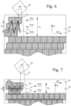
- Figure 5 illustrates schematically an embodiment of a printing process.
- the strip switch moves the position of the laser illumination pattern 13 on the writing plane in a cyclic motion pattern.
- a complete cycle of the cyclic motion pattern is performed within a certain period. This period is less or equal to a quotient of a width 48 in the scan direction 62 of the laser illumination pattern 13 on the writing plane divided with a constant scan velocity of the relative position between the SLM and the writing plane. This ensures that the complete intended area to be written at the target surface in the scan direction 62 is illuminated at least once.
- the SLM and the pulsed laser light are controlled, synchronized with the cyclic motion pattern, to generate the individual specimens of the laser illumination patterns 13 at the at least two predetermined positions in the sweep direction 61.
- a laser illumination pattern 13 is written in a first strip 45A but letting the pulsed laser light of the set of switched exposure beams reach the target surface.
- the laser pule is short enough to allow the relative position change between the SLM and the writing plane to continue also during the exposure.
- the relative position change continues to move the position of the exposed area in the scan direction 62.
- the strip switch changes the position of the exposure in the sweep direction 61, to a second strip 45B.
- a next laser pulse is admitted and a laser illumination pattern 13 is written in the second strip 45B.
- the strip switch then returns the exposure beams to the first strip 45A and the cyclic motion pattern can start allover again.
- the stage positioning device is in other words preferably further configured for mechanically changing a relative position between the SLM and the writing plane in steps 75 in the sweep direction 61.
- an amplitude 74 of the cyclic motion pattern in the sweep direction 61 is in a general case equal or larger than the steps 75 in the sweep direction times (m-1)/m, where m is the number of predetermined positions in said sweep direction 61.
- an amplitude 74 of the cyclic motion pattern in the sweep direction 61 is at least half the step 75 in the sweep direction 61.
- a writing process involving more than two simultaneous strips 45A-C is schematically illustrated.
- the control module is thereby arranged for controlling the SLM to generate laser illumination patterns at more than two predetermined positions in the sweep direction, wherein the more than two predetermined positions are equidistant in the sweep direction.
- the relative speed between the SLM and the writing plane here becomes about one third comparing to a situation where the strips are written consecutively.
- the necessary amplitude 74 of the switch in the sweep direction is at least 2/3 compared to the step 75 between consecutive scans.
- the distance in the scan direction between the individual laser illumination pattern 13 of the respective strips 45A-C is also equidistant.
- the laser illumination pattern 13 of strip 45B is displaced in the scan direction relative the laser illumination pattern 13 of strip 45A by the same amount that the laser illumination pattern 13 of strip 45C is displaced in the scan direction relative the laser illumination pattern 13 of strip 54B.
- this is not absolutely necessary and depends on the operation possibilities of the strip switch.
- the change rate of the strip switch is twice between strip 45C and 45A compared to the rate between strip 45A and 45B.
- MEMS mirrors are provided in different versions.
- a quasi-static MEMS mirror or a resonant MEMS mirror can be used.
- the Figures 5 and 6 may illustrate an implementation using a quasi-static MEMS mirror.
- the position in the sweep direction 61 can be halted in well-determined positions. This allows for selection of the equidistant strips at selected points in time.
- the points in time are selected to be regular, which may be an advantage when controlling the laser pulse timing. However, in other embodiments, the selected points in time may also be different for the different strip changes.
- a quasi-static MEMS mirror will in other words shift the 2D-SLM image - the laser illumination pattern 13 -to discrete positions in the sweep direction 61.
- the velocity in the scan direction 62 is then reduced by a factor equal to the number of different positions in the sweep direction 61.
- a mirror cycle thereby consists of a few, typically 2-5, small movements in the sweep direction followed by a large return movement in the negative sweep direction.
- MEMS mirrors Another choice of MEMS mirrors is a resonant MEMS mirror. Such a mirror oscillates continuously between different states, in accordance with a resonance frequency of the system. This opens up for relatively cost-efficient and simple arrangements, but has the drawback that the point in time when different positions are reached is not independently controllable.
- the strip switch moves the position of the laser illumination pattern on the writing plane in a cyclic motion pattern with a frequency equal to a resonance frequency of the MEMS mirror.
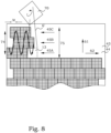
- Figure 7 illustrates schematically an embodiment of a dual-strip writing that could be achieved using a resonant MEMS mirror.
- the curve 76 indicates the motion of the position for the center of the laser illumination pattern 13 if a laser would be constantly turned on.
- This curve 76 is composed by a constant velocity in the scan direction 62 of the mechanical movement caused by the stage positioning device and an oscillating motion in the sweep direction 61 caused by the resonating MEMS mirror.
- a laser pule is turn on and laser illumination pattern 13 is written on the target surface 44.
- a resonant MEMS mirror would move the 2D-SLM image - the laser illumination pattern 13 - to different possible positions in the sweep direction 61.
- the velocity in scan direction 62 is reduced by number of used positions in the sweep direction 61.
- the mirror moves image in the sweep direction 61 with an oscillation frequency corresponding to a fraction, typically 2-4, of the SLM update frequency.
- the positions in the sweep direction are the outcome of the combination of exposure light pulse rate, mirror deflection amplitude and frequency, and laser synchronization in relation to resonant phase. For 2-4 positions in the sweep direction, the strips can be placed exactly equidistant.
- Figure 8 illustrates schematically another embodiment of a three-strip writing that could be achieved using a resonant MEMS mirror.
- three equidistant positions in the sweep direction 61 are selected.
- a laser pulse is emitted and a laser illumination pattern 13 is written on the target surface 44.
- the amplitude 74 of the resonant mirror movement has to be larger than for the quasi-static MEMS mirror case, and may even be larger than the step 75 in the sweep direction 61.
- the laser pulse has to be controlled to occur with different time separations.
- Figure 9 illustrates schematically another embodiment of a four-strip writing that could be achieved using a resonant MEMS mirror.
- the amplitude 74 of the resonant mirror movement is almost as large as the step 75 in the sweep direction 61.
- Four equidistant strips 45A-D are possible to achieve in parallel writing.
- the necessary mechanical speed in the scan direction can thereby be reduced to 1 ⁇ 4.
- one may notice that the time difference ⁇ t between the writing occasions for the different strips is the same, i.e. the shift between the different strips is equidistant also in the scan direction 62. This is possible to achieve together with the positioning of the four strips equidistant in the sweep direction 61.
- the laser pulses thus have to be controlled to occur at these regular time instances, with a certain phase shift between the resonant motion and the occasions for the laser pulses. Since the SLM typically is moved constantly relative the target surface, the exposure occasions, equidistant in time, also results in equidistant spatial offsets of the laser illumination patterns 13, as mentioned above.
- the present technical solution is particularly well suited if the pattern generator is a direct writer. The speed of writing is then of most significant importance.
- the technical solution may also be applicable to e.g. mask writers, even if the velocity in scan direction currently typically is not critically high for such write engine.
- Such writers are typically based on an Acousto-Optic Modulator (AOM) and/or Acousto-Optic Deflector (AOD) writer operation.
- AOM Acousto-Optic Modulator
- AOD Acousto-Optic Deflector
- the present alternation between strips may be used for alternating the sweeps between several strips to reduce the required X-velocity or number of strokes for multipass writing. It is however presently concluded that such an implementation may require a large redesign to fit the mirror after the deflector.
- Figure 10 is a flow diagram of steps of an embodiment of a method for operating a pattern generator.
- print data is provided, representing a pattern to be generated.
- Pulsed laser light is in step S20 supplied to a SLM.
- the SLM is in step S30 controlled to generate laser illumination patterns according to the print data.
- a relative position between the SLM and the writing plane is mechanically changed in a scan direction, parallel to the writing plane.
- an optical end system is arranged for positioning the laser illumination pattern on a writing plane.
- a strip switch of the optical end system is controlled to optically move a position of the laser illumination pattern on the writing plane in a sweep direction, parallel to the writing plane but perpendicular to the scan direction.
- the controlling of the spatial light module and the supplying of pulsed laser light is further performed in dependence of the controlling of the strip switch for controlling the SLM to generate individual specimens of the laser illumination patterns at at least two predetermined positions in the sweep direction, with a distance in the sweep direction relative to a closest other predetermined position being less or equal to a width in the sweep direction of the laser illumination pattern on the writing plane.
- steps S20-S55, and optionally also step S10 are performed in cooperation with each other and typically at least partially overlapping in time. This is illustrated by the dotted box S15.
- the step S55 of controlling the strip switch moves the position of the laser illumination pattern on the writing plane in a cyclic motion pattern.
- a complete cycle of the cyclic motion pattern is performed within a period less or equal to a quotient of a width in the scan direction of the laser illumination pattern on the writing plane divided with a constant scan velocity of the relative position between the SLM and the writing plane.
- the controlling of the spatial light module and the supplying of pulsed laser light are synchronized with the cyclic motion pattern to generate the individual specimens of the laser illumination patterns at the at least two predetermined positions in the sweep direction.
- the method comprises the further step S60, in which a relative position between the SLM and the writing plane is mechanically changed in steps in the sweep direction.
- An amplitude of the cyclic motion pattern in the sweep direction is equal or larger than the steps in the sweep direction.
- the step S30 of controlling the SLM controls the SLM to generate laser illumination patterns at more than two predetermined positions in the sweep direction.
- the more than two predetermined positions are equidistant in the sweep direction.
- the step S55 of controlling the strip switch comprises controlling of a microelectromechanical-system mirror.
- the step S55 of controlling the strip switch comprises controlling of a resonant microelectromechanical-system mirror.
- the step S55 of controlling the strip switch comprises moving the position of the laser illumination pattern on the writing plane in a cyclic motion pattern with a frequency equal to a resonance frequency of the microelectromechanical-system mirror.
- the step S55 of controlling the strip switch comprises controlling of a quasi-static microelectromechanical-system mirror.
Landscapes
- Physics & Mathematics (AREA)
- General Physics & Mathematics (AREA)
- Engineering & Computer Science (AREA)
- Plasma & Fusion (AREA)
- Optics & Photonics (AREA)
- Exposure Of Semiconductors, Excluding Electron Or Ion Beam Exposure (AREA)
- Mechanical Light Control Or Optical Switches (AREA)
Priority Applications (4)
| Application Number | Priority Date | Filing Date | Title |
|---|---|---|---|
| EP23182592.8A EP4485072A1 (de) | 2023-06-30 | 2023-06-30 | Mustergenerator und verfahren zur ansteuerung eines mustergenerators |
| TW113118691A TW202503429A (zh) | 2023-06-30 | 2024-05-21 | 圖形產生器及驅動圖形產生器的方法 |
| PCT/EP2024/066783 WO2025002879A1 (en) | 2023-06-30 | 2024-06-17 | Pattern generator and method for driving pattern generator |
| CN202480031597.8A CN121079636A (zh) | 2023-06-30 | 2024-06-17 | 图案生成器和用于驱动图案生成器的方法 |
Applications Claiming Priority (1)
| Application Number | Priority Date | Filing Date | Title |
|---|---|---|---|
| EP23182592.8A EP4485072A1 (de) | 2023-06-30 | 2023-06-30 | Mustergenerator und verfahren zur ansteuerung eines mustergenerators |
Publications (1)
| Publication Number | Publication Date |
|---|---|
| EP4485072A1 true EP4485072A1 (de) | 2025-01-01 |
Family
ID=87060665
Family Applications (1)
| Application Number | Title | Priority Date | Filing Date |
|---|---|---|---|
| EP23182592.8A Withdrawn EP4485072A1 (de) | 2023-06-30 | 2023-06-30 | Mustergenerator und verfahren zur ansteuerung eines mustergenerators |
Country Status (4)
| Country | Link |
|---|---|
| EP (1) | EP4485072A1 (de) |
| CN (1) | CN121079636A (de) |
| TW (1) | TW202503429A (de) |
| WO (1) | WO2025002879A1 (de) |
Citations (5)
| Publication number | Priority date | Publication date | Assignee | Title |
|---|---|---|---|---|
| EP1672431A1 (de) * | 2004-12-17 | 2006-06-21 | ASML Netherlands BV | Lithografischer Apparat, System und Verfahren zur Herstellung einer Vorrichtung |
| EP1795966B1 (de) * | 2005-12-09 | 2008-06-18 | ASML Netherlands BV | Lithographischer Apparat und Verfahren zur Herstellung einer Vorrichtung |
| US20090059295A1 (en) * | 2005-09-30 | 2009-03-05 | Mitsuru Mushano | Plotting Device and Image Data Creation Method |
| WO2011107602A2 (en) * | 2010-03-05 | 2011-09-09 | Micronic Mydata AB | Methods and device for laser processing |
| US20160085156A1 (en) * | 2014-08-08 | 2016-03-24 | David A. Markle | Maskless digital lithography systems and methods with image motion compensation |
-
2023
- 2023-06-30 EP EP23182592.8A patent/EP4485072A1/de not_active Withdrawn
-
2024
- 2024-05-21 TW TW113118691A patent/TW202503429A/zh unknown
- 2024-06-17 WO PCT/EP2024/066783 patent/WO2025002879A1/en not_active Ceased
- 2024-06-17 CN CN202480031597.8A patent/CN121079636A/zh active Pending
Patent Citations (5)
| Publication number | Priority date | Publication date | Assignee | Title |
|---|---|---|---|---|
| EP1672431A1 (de) * | 2004-12-17 | 2006-06-21 | ASML Netherlands BV | Lithografischer Apparat, System und Verfahren zur Herstellung einer Vorrichtung |
| US20090059295A1 (en) * | 2005-09-30 | 2009-03-05 | Mitsuru Mushano | Plotting Device and Image Data Creation Method |
| EP1795966B1 (de) * | 2005-12-09 | 2008-06-18 | ASML Netherlands BV | Lithographischer Apparat und Verfahren zur Herstellung einer Vorrichtung |
| WO2011107602A2 (en) * | 2010-03-05 | 2011-09-09 | Micronic Mydata AB | Methods and device for laser processing |
| US20160085156A1 (en) * | 2014-08-08 | 2016-03-24 | David A. Markle | Maskless digital lithography systems and methods with image motion compensation |
Also Published As
| Publication number | Publication date |
|---|---|
| WO2025002879A1 (en) | 2025-01-02 |
| TW202503429A (zh) | 2025-01-16 |
| CN121079636A (zh) | 2025-12-05 |
Similar Documents
| Publication | Publication Date | Title |
|---|---|---|
| US10261421B2 (en) | Controller for optical device, exposure method and apparatus, and method for manufacturing device | |
| US6859223B2 (en) | Pattern writing apparatus and pattern writing method | |
| US7215409B2 (en) | Image forming method and apparatus | |
| JP3938714B2 (ja) | 露光装置 | |
| RU2232411C2 (ru) | Усовершенствованный генератор рисунков | |
| KR101087862B1 (ko) | 연속적인 직접-기록 광 리쏘그래피 장치 및 방법 | |
| TWI430053B (zh) | A drawing system, a correction device for a tracing data, a method of manufacturing the substrate, a computer program product | |
| JP2009044060A (ja) | 描画装置および描画方法 | |
| JP7416090B2 (ja) | 光学装置、露光装置、フラットパネルディスプレイの製造方法、及びデバイス製造方法 | |
| TWI430052B (zh) | A drawing system, a correction device for a tracing data, a method of manufacturing the substrate, a computer program product | |
| KR101170067B1 (ko) | 묘화 장치 및 묘화 방법 | |
| JP2007305987A (ja) | 干渉露光及び他の露光を用いるリソグラフィ装置及びデバイス製造方法 | |
| KR101906538B1 (ko) | 교차 기입 전략 | |
| JP2006186371A (ja) | リソグラフィ装置及びデバイス製造方法 | |
| EP4485072A1 (de) | Mustergenerator und verfahren zur ansteuerung eines mustergenerators | |
| JP2009152607A (ja) | デバイス制御方法及び装置 | |
| JP4638826B2 (ja) | 描画装置及び描画方法 | |
| JP2004128272A (ja) | パターン描画装置およびパターン描画方法 | |
| US20020057328A1 (en) | Image recording method and image recording apparatus | |
| US7499146B2 (en) | Lithographic apparatus and device manufacturing method, an integrated circuit, a flat panel display, and a method of compensating for cupping | |
| JP2010021409A (ja) | 露光方法、露光装置および基板製造方法。 | |
| JP4017337B2 (ja) | 画像記録方法及び装置 | |
| JP2009302460A (ja) | 露光方法、露光装置、および電子デバイスの製造方法 |
Legal Events
| Date | Code | Title | Description |
|---|---|---|---|
| PUAI | Public reference made under article 153(3) epc to a published international application that has entered the european phase |
Free format text: ORIGINAL CODE: 0009012 |
|
| STAA | Information on the status of an ep patent application or granted ep patent |
Free format text: STATUS: THE APPLICATION HAS BEEN PUBLISHED |
|
| AK | Designated contracting states |
Kind code of ref document: A1 Designated state(s): AL AT BE BG CH CY CZ DE DK EE ES FI FR GB GR HR HU IE IS IT LI LT LU LV MC ME MK MT NL NO PL PT RO RS SE SI SK SM TR |
|
| STAA | Information on the status of an ep patent application or granted ep patent |
Free format text: STATUS: THE APPLICATION IS DEEMED TO BE WITHDRAWN |
|
| 18D | Application deemed to be withdrawn |
Effective date: 20250702 |