EP4485097A1 - Procédé d'installation assistée par ordinateur de composants électriques d'une machine agencés de manière décentralisée dans l'espace - Google Patents
Procédé d'installation assistée par ordinateur de composants électriques d'une machine agencés de manière décentralisée dans l'espace Download PDFInfo
- Publication number
- EP4485097A1 EP4485097A1 EP23181929.3A EP23181929A EP4485097A1 EP 4485097 A1 EP4485097 A1 EP 4485097A1 EP 23181929 A EP23181929 A EP 23181929A EP 4485097 A1 EP4485097 A1 EP 4485097A1
- Authority
- EP
- European Patent Office
- Prior art keywords
- installation
- component
- identifier
- identification
- machine
- Prior art date
- Legal status (The legal status is an assumption and is not a legal conclusion. Google has not performed a legal analysis and makes no representation as to the accuracy of the status listed.)
- Pending
Links
Images
Classifications
-
- G—PHYSICS
- G05—CONTROLLING; REGULATING
- G05B—CONTROL OR REGULATING SYSTEMS IN GENERAL; FUNCTIONAL ELEMENTS OF SUCH SYSTEMS; MONITORING OR TESTING ARRANGEMENTS FOR SUCH SYSTEMS OR ELEMENTS
- G05B19/00—Program-control systems
- G05B19/02—Program-control systems electric
- G05B19/04—Program control other than numerical control, i.e. in sequence controllers or logic controllers
- G05B19/042—Program control other than numerical control, i.e. in sequence controllers or logic controllers using digital processors
- G05B19/0423—Input/output
-
- G—PHYSICS
- G05—CONTROLLING; REGULATING
- G05B—CONTROL OR REGULATING SYSTEMS IN GENERAL; FUNCTIONAL ELEMENTS OF SUCH SYSTEMS; MONITORING OR TESTING ARRANGEMENTS FOR SUCH SYSTEMS OR ELEMENTS
- G05B19/00—Program-control systems
- G05B19/02—Program-control systems electric
- G05B19/04—Program control other than numerical control, i.e. in sequence controllers or logic controllers
- G05B19/042—Program control other than numerical control, i.e. in sequence controllers or logic controllers using digital processors
- G05B19/0426—Programming the control sequence
-
- G—PHYSICS
- G05—CONTROLLING; REGULATING
- G05B—CONTROL OR REGULATING SYSTEMS IN GENERAL; FUNCTIONAL ELEMENTS OF SUCH SYSTEMS; MONITORING OR TESTING ARRANGEMENTS FOR SUCH SYSTEMS OR ELEMENTS
- G05B2219/00—Program-control systems
- G05B2219/20—Pc systems
- G05B2219/25—Pc structure of the system
- G05B2219/25061—Configuration stored in central database
-
- G—PHYSICS
- G05—CONTROLLING; REGULATING
- G05B—CONTROL OR REGULATING SYSTEMS IN GENERAL; FUNCTIONAL ELEMENTS OF SUCH SYSTEMS; MONITORING OR TESTING ARRANGEMENTS FOR SUCH SYSTEMS OR ELEMENTS
- G05B2219/00—Program-control systems
- G05B2219/20—Pc systems
- G05B2219/25—Pc structure of the system
- G05B2219/25068—Check correct configuration of device
Definitions
- the present invention relates generally to the field of planning and assembly of machines such as automation systems, and in particular to a computer-aided installation of spatially decentralized electrical components of a machine.
- the underlying object of this invention is in particular to provide a solution which enables a simple, fast, safe and error-free installation of electrical components and at least partially overcomes the above-mentioned disadvantages of the prior art.
- the subject matter of the invention is a method having the features of claim 1, a system having the features of claim 13, a computer program having the features of claim 14 and a device having the features of claim 15. Further features and details of the invention emerge from the respective subclaims, the description and the drawings. Features and details that are in the connection with the method according to the invention, of course also in connection with the system according to the invention, the computer program according to the invention and the device according to the invention, and vice versa, so that with regard to the disclosure of the individual aspects of the invention, reference is or can always be made to each other.
- the subject matter of the invention is in particular a preferably computer-implemented method for a computer-aided installation of spatially decentralized electrical components of a machine, in particular an electrical system, preferably an automation system.
- the following steps of the method can be provided, which are preferably carried out one after the other and/or repeatedly:
- provision can be made of an installation specification, in particular an electrical circuit diagram.
- the installation specification can specify an assignment of the respective components to one or more installation locations of the machine.
- the installation specification can be provided in digital form, for example, and can be stored non-volatilely in a data storage device and/or a database.
- the electrical circuit diagram can be created, for example, using software via a graphical user interface.
- the graphical user interface enables, for example, a selection and placement of symbolic representations of electrical equipment of the machine, e.g. the components.
- the equipment can be connected to one another in order to represent the electrical connections in the circuit diagram.
- data structures and validation rules can be implemented to ensure the consistency and freedom from errors of the circuit diagram.
- Installation locations for the components can be specified in the circuit diagram and, if necessary, specified in a connection plan.
- the connection diagram can indicate the exact positions and connections of these installation locations to provide a clear and unambiguous representation of the electrical wiring and connections. This allows installers to efficiently and correctly make the connections between the equipment and the corresponding slots.
- the installation locations include, for example, physical slots and/or physical connections and/or local areas of the machine.
- the installation specification can specify an installation identifier, in particular equipment identifier, and an article identifier, in particular article number, for one or more installation locations, preferably as a unique identifier. This enables the components to be clearly assigned to the installation locations, which preferably represents the actual installation of the components on the machine.
- the installation marking and preferably the equipment marking refers in particular to the marking of components or, in general, electrical equipment to provide information about their type and/or identity and/or function and/or properties and/or safety features. These markings can traditionally not only be indicated in the circuit diagram, but can also be applied to the equipment itself in the form of physical identification means such as stickers, signs, labels or markings.
- the installation or equipment marking can include important information such as the device name and/or serial number and/or voltage range and/or power consumption and/or manufacturer information and/or warnings and/or other relevant information.
- the installation or equipment marking can be determined when the machine is planned and stored in the circuit diagram. In conventional solutions, the installation or equipment marking is also physically attached manually to the equipment such as the component.
- the receiving of an identifier of a component to be installed can be provided.
- the identifier can differ from the installation marking in the installation specification and in particular from the conventionally used installation or equipment markings.
- the identifier can also be attached to the component via a physical means of identification, e.g. printed on.
- a physical means of identification e.g. printed on.
- this can be done originally and generically for the components, regardless of a specific circuit diagram or a specific installation.
- components such as cables can originally be provided with a series and/or article marking or a network-capable connection module can originally have a network address.
- the use of a physical means of identification such as a print of this information enables the identifier to be read in easily by machine in order to be able to receive the read identifier in the form of digital data.
- the received identifier can be assigned to at least one of the installation markings on the basis of the article markings in the installation specification.
- the article markings can be used to determine which of the installation markings the received identifier can be assigned to.
- the installation markings can also indicate different installation locations for which the installation markings are specified by the installation specification.
- the assignment thus enables at least one of the installation locations for the installation of the component to be installed to be determined on the basis of the assignment of the received identifier in a further process step.
- Several of the installation identifiers can also be considered for the assignment and thus also several installation locations, so that the desired installation location or the desired installation identifier can be selected if necessary.
- the invention not only makes it possible to dispense with the otherwise usual and time-consuming subsequent attachment of the installation marking to the component, it even allows a dynamic selection of suitable installation locations to be made during installation.
- the received identifier comprises a component identifier for the component to be installed, wherein the component identifier comprises a series identifier and/or an article identifier and/or a manufacturer identifier and/or network address, wherein preferably the article identifier of the component identifier and/or the article identifiers specified in the installation specification are each designed as generic identifiers of the components.
- the component identifier can only comprise original and therefore generic identifiers of the component. This can reduce the effort and susceptibility to errors due to the subsequent attachment of such identifiers.
- the assignment of the received identifier may further comprise: determining the generic suitability of the component to be installed for installation at at least one of the installation locations.
- the component to be installed may be assigned at least one of the article identifiers specified for the installation locations in the Installation specifications can be assigned to the component identification of the received identifier based on the article identification.
- the article identification of the component identification is simply compared with the article identifications in the installation specification.
- the article identifications in the installation specification are also assigned to the installation identifications and thus to the installation locations ("specified for the installation location"), so that a (suitable) installation location for the component can also be determined in this way.
- the specification of the article identifications and installation identifications for the installation locations can be provided in such a way that the article identifications indicate the suitability of the type specified by the article identifications for installation at these installation locations. Suitability can therefore preferably be determined if the article identifications indicate a match.
- At least one of the installation locations for which the component to be installed is suitable for installation can be selected. Since the article identifiers only indicate the type suitable for installation and not a specific component, several installation locations for the installation of the component can be considered.
- the component identifier of the received identifier can be assigned at least partially, in particular at least the series identifier, to the installation identifier specified for the selected installation location. In this way, the component can be specified for installation at the installation location and therefore receive the installation identifier specified for the selected installation location.
- a respective type of component is specified both by the received identifier and by the article markings in the installation specification, wherein in order to determine the at least one installation location for the component to be installed, it can also be provided: determining a generic suitability of the component to be installed for installation at at least one of the installation locations by comparing the type of component to be installed with the types according to the article markings in the installation specification in order to classify the component to be installed as suitable for installation at at least one of the installation locations.
- the identifier comprises at least a unique and preferably one-to-one identification for the component to be installed.
- the component to be installed can still be clearly and preferably one-to-one distinguished from the other components, in particular also from other manufacturers of the components, as with conventional identification.
- This advantage over known solutions is preferably achieved by providing a combination of a serial identification and manufacturer identification or a network address to identify the component and preferably functionally replacing a component-side installation identification on the component to be installed for the installation.
- the updated installation specification can be used in this way for further installation of the machine.
- the updated installation specification can also be accessed at least partially automatically if necessary in order to carry out and/or check the physical installation of the machine at least partially automatically, e.g. to check for correctness with respect to the installation specification.
- the serial identification can be designed to clearly identify the component and in particular an operating resource and thus distinguish it from other components or operating resources.
- Each of the serial markings used can therefore be unique to avoid confusion.
- the serial markings can be designed as serial numbers with a combination of numbers and/or letters.
- the invention can provide that the components are designed as electrical equipment of the machine in the form of an electrical system, which are assigned to different types, wherein the components according to a first type comprise several decentrally arranged connecting elements, in particular cables, and according to a second type comprise several decentrally arranged connecting modules, wherein the connecting modules each comprise several connection points for electrical connection to the connecting elements, to control other devices on the machine, in particular sensors and/or actuators, via the connecting elements.
- connection modules can be connected decentrally (in relation to a control cabinet that would otherwise be intended for central installation) via the connection modules.
- the received identifier comprises a component identification for the component to be installed, wherein the component identification can comprise different ones of the following identifications depending on a type of component to be installed: a unique identification, a serial identification, an article identification, a manufacturer identification, network address, preferably a MAC address, a machine-readable code, preferably a QR code.
- the identifier has a serial identification, in particular a serial number, in order to identify the component to be installed - preferably uniquely - for the manufacturer of the component.
- the serial identification can be manufacturer-related and thus ensure unique identification only for the manufacturer.
- the identifier can have an article identification, preferably article number, in order to identify the type and/or technical properties of the component.
- the article identification can also identify the component for the manufacturer - preferably uniquely.
- the article identification can also be manufacturer-related and thus ensure unique identification only for the manufacturer of the component.
- the identifier can have a manufacturer identification that identifies the manufacturer of the component. The combination of article identification and manufacturer identification or series identification and manufacturer identification can also result in unique identification for different manufacturers.
- the installation specification includes a predefined specification on a modular and/or decentralized structure of the machine, in particular the electrical system, preferably an electrical and/or mechanical and/or network connection plan.
- the component to be installed is a connecting element, in particular a cable, and/or a connecting module for the decentralized connection of sensors and/or actuators via connecting elements to a control device.
- the received identifier and/or preferably a component identification of the received identifier is an original identification of the component to be installed, wherein preferably the identifier and in particular the component identification at the time of manufacture and/or at the time of has been attached to the component to be installed at the time of assembly, in particular printed and/or applied and/or glued by laser engraving and/or laser labeling, wherein the identifier preferably comprises a code, in particular a bar code or QR code, in order to be recorded for reception by a reading device.
- system according to the invention thus brings with it the same advantages as have been described in detail with reference to a method according to the invention.
- the system can be suitable for carrying out the steps of a method according to the invention.
- the invention also relates to a computer program, comprising instructions which, when the computer program is executed by a computer, cause the computer to carry out the steps of a method according to the invention.
- a device for data processing can be the subject of the invention, comprising means for carrying out the steps of a method according to the invention.
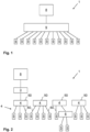
- centralized control cabinet systems see Fig. 1
- decentralized systems see Fig. 2
- control modules are attached directly to the systems.
- the corresponding processes are carried out by different people, such as system planners, electrical planners, installers, system programmers, etc.
- a special feature of decentralized systems is the distribution of the modules at different points on a machine in comparison to centralized control cabinet systems.
- FIG. 1 A central interconnection by means of a control cabinet 9 is shown schematically in order to compare this with a decentralized interconnection by means of spatially decentralized electrical components 4 of a machine 1 in Fig. 2
- the components 4 can comprise various types such as connecting elements 60, for example cables, and connecting modules 50.
- connecting elements 60 for example cables
- connecting modules 50 instead of connecting all devices 5 such as sensors and actuators directly to the control cabinet 9 - as in Fig. 1 shown - can be used in decentralized interconnection in Fig. 2 several components 4, i.e. in particular the connection modules 50, are used to connect the devices 5 in the field.
- the connection modules 50 like the control cabinet 9, enable the devices 5 to be coupled to a control device 8 such as a PLC (i.e.
- connection modules 50 can be provided in a decentralized manner and distributed in the vicinity of the devices 5.
- a central control cabinet 9 is at least partially divided into several decentralized connection modules 50.
- the connection modules 50 thus only partially connect the devices 5, whereby the connection modules 50 together or, for example, one and/or several connection modules 50 can carry out the entire connection via one and/or several hubs 6.
- a controller module 3 also referred to as master module 3 can be connected upstream of several of the individual connection modules 50.
- the controller module 3 can then control the associated Configure connection modules 50.
- the connection modules 50 connected thereto can be regarded as peripheral connection modules 50. It is also possible for the interconnection to be further subdivided using at least one hub 6.
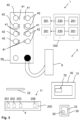
- Fig. 3 1 shows parts of a system 2 according to embodiments of the invention.
- the system 2 can be provided for computer-aided installation of spatially decentralized electrical components 4 of a machine 1.
- the components 4 can thus comprise at least some of the operating resources which are required for the installation and thus for providing the function of the machine 1.
- the components 4 can each comprise an identifier 11 which is designed to identify the component 4 at least uniquely and/or according to its type.
- the identifier 11 can have a component identifier 200 which can result from a combination or compilation of several individual identifiers such as an article identifier 201 and/or a series identifier 202 and/or a manufacturer identifier 203 and/or a network address 208.
- the component identifier 200 can have only one of these identifiers, e.g. B. the network address 208.
- the system 2 can be provided with a reader 22 for detecting the identifier 11.
- the reader 22 can be designed as a mobile, portable device which a user can use directly on the component 4 such as a cable 60 to detect the identifier 11.
- a device 30 can be provided in the system 2 for data processing.
- the device 30, specifically a computer program 20 in a data memory 33 of the device 30, can receive the detected identifier 11 and assign it to at least one installation marking 230 on the basis of generic markings 201 in an installation specification 300 for the computer-aided, decentralized installation of the electrical components 4 in a machine 1.
- the installation specification 300 can be designed as an electrical circuit diagram and provided digitally.
- the installation specification 300 is stored at least partially in the data memory 33 of the device 30 and/or in an external data memory (e.g. a cloud-based database) in a non-volatile manner.
- the installation specification 300 is designed, for example, as a digital electrical circuit diagram 300, which in particular has a (digitized) connection plan.
- Fig. 3 the installation specification 300 is shown schematically in such a way that several installation markings 230, in particular each in the form of a device marking, and article markings 201, in particular each in the form of an article number, are assigned to one another and are defined for several installation locations 301.
- the installation locations 301 are, for example, the connections of the machine 1 intended for installation and include, for example, the Fig. 3 shown connection points 42 of the connection modules 50.
- the components 4 can comprise connection elements 60 such as cables or also the connection modules 50, which, depending on the type, can be connected to one or more of the connections of the machine 1 according to the connection plan.
- the article identification 201 can specify the type and the installation identification 230 can be clearly assigned to the installation location 301, i.e., for example, one of the connection points 42.
- a certain component 4 can be connected based on its type.
- a specific component 4 e.g.
- a specific cable of a certain type and with a certain serial number does not have to be assigned to a certain installation location 301 in the installation specification 300 from the outset - it is sufficient to make this assignment flexibly during installation.
- the assignment can be permanently stored in the installation specification 300 in order to document the installation accordingly.
- an automated check is then carried out to determine whether component 4 has actually been connected to the selected installation location 301.
- the component identification 200 of the connected component 4 can be determined and compared with the stored assignment in the installation specification 300.
- a computer program 20 according to embodiments of the invention is shown, which comprises instructions which, when the program is executed by a computer 30, cause the computer 30 to carry out the steps of the method 100 according to embodiments of the invention.
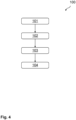
- Fig. 4 process steps of the process 100 are visualized.
- the installation specification 300 is used for installation because it assigns the components 4 to one or more installation locations 301 of the machine 1.
- the installation specification 300 indicates at which installation locations 301 the components 4 are to be installed according to a predefined plan. This assignment can be specified step by step for all components 4 during installation, but can previously only be specified with regard to the required type of components 4 in the installation specification 300. Therefore, the installation specification 300 can specify an installation identifier 230, in particular equipment identifier, and an article identifier, in particular article number, for each of the one or more installation locations 301, preferably as a unique identifier.
- the article identification 201 can indicate the required type of component 4 for one of the installation locations 301 and the installation identification 230 can clearly assign the component 4, which is yet to be specified, to this installation location 301 according to the required type.
- the identifier 11 of a component 4 of the components 4 to be installed can first be received according to a second method step 102 and assigned to at least one of the installation identifiers 230 on the basis of the article identifiers 201 in the installation specification 300 according to a third method step 103. Then, according to a fourth method step 104, at least one of the installation locations 301 for the installation of the component 4 to be installed can be determined on the basis of the assignment 103 of the received identifier 11.
- those installation locations 301 for the installation of the component 4 to be installed and thus as installation locations 301 suitable for the installation can be determined for which an article identifier 201 is specified in the installation specification 300 that indicates the type of component 4 to be installed.
- the component 4 that is installed at this installation location 301 can then be specified.
- the installation at this installation location 301 can also be documented, e.g. by storing at least part of the identifier 11 in the installation template 300 assigned to the installation identifier 230 defined for the selected installation location 301.
- the received identifier 11 can be used.
- the received identifier 11 can comprise a component identifier 200 for the component 4 to be installed, wherein the component identifier 200 preferably comprises a series identifier 202 and/or an article identifier 201 and/or a manufacturer identifier 203 and/or network address 208 (see. Fig. 3 ). This makes it possible to determine whether the component 4 to be installed is suitable for installation at at least one of the installation locations 301.
- the component 4 to be installed can be assigned to at least one of the article identifiers 201 specified for the installation locations 301 in the installation specification 300 using the article identifier 201 of the component identifier 200 of the received identifier 11, for example by determining which of the article identifiers 201 in the installation specification 300 the article identifier 201 of the component identifier 200 matches.
- the installation locations 301 for which these matching article identifiers 201 are specified are determined in this way and can be selected for installation.
- the component identification 200 of the received identifier 11 can then be assigned at least partially, in particular at least the serial identification 202, to the installation identification 230 specified for the selected installation location 301.
- the selection can be made manually by a user, e.g. via a graphical user interface 32 (see. Fig. 3 ).
- the installation specification 300 updated according to the documentation can then be used to continue the installation of machine 1 and can be successively updated again each time one of the components 4 is installed.
- the method 100 not only enables a dynamic specification of the components 4 to specific installation locations 301, but also further support of a user (e.g. installer) during installation.
- installation information based on the assignment 103 of the received identifier can be output, in particular on a graphical user interface 32 and/or via display elements 41 of the connection modules 50.
- the installation information enables an indication of the at least one determined installation location 301 and preferably at least one of the installation locations 301 for which the component 4 to be installed is suitable for installation.
- the installation locations 301 include, for example, the connection points 42, to which one of the display elements 41 can be assigned.
- the assignment can be made clear to a user by the corresponding spatial arrangement of the display elements 41 in the vicinity of the respectively assigned connection points 42 on the connection module 50, as shown in Fig. 3 can be seen as an example.
- the display elements 41 can be activated, for example, in order to display the associated connection points 42 that correspond to the determined installation locations 301. The user can then make the selection, which can again be visually confirmed by the display elements 41 if necessary.
- the installation location 301 can also be selected automatically, e.g. according to predefined criteria in order to determine the best suitability. The selected installation location 301 can then be issued as an installation suggestion.
- the user interface 32 visualizes a digital twin of at least part of the machine 1, and preferably visualizes a topology and/or a mechanical and/or an electrical connection plan of at least part of the machine 1. It is thus possible to visually indicate a type of map with the installation locations 301, on which the determined installation locations 301 are highlighted.
- the determined installation locations 301 can be displayed using virtual and/or augmented reality or communicated via an acoustic output.
- the received identifier 11 and/or preferably a component identification 200 of the received identifier 11 can be an original identification of the component 4 to be installed, in contrast to the installation identification 230.
- the identifier 11 does not have to be generated subsequently based on an installation specification 300.
- the identifier 11 can always be the same for different installations and installation specifications 300, in particular since it is unique for the specific component 4.
- the identifier 11 can have been attached to the component 4 to be installed at the time of manufacture and/or at the time of assembly, in particular printed and/or by laser engraving and/or laser labeling, wherein the identifier 11 can comprise a code, in particular a bar code or QR code.
- the automated storage described above can be advantageous. For example, all information is stored in the right place in the various documents of the installation specification, such as the circuit diagram or the connection plan. The person carrying out the respective step then only has to acknowledge the entries.
- the components mentioned can be, for example, the components 4 and/or other components of the machine 1.
- the installation documentation can, for example, document at least one of the following pieces of information: work steps of the user with additional information on the work steps such as processing time, which machine is being worked on, which user, for example which installer or fitter, carried out the activities and when, which component has been wired and/or cabled, has the assembly step been completed, which port/connection point was used, are there any open cables and what are the properties of the open cable, e.g. length, environmental parameters, e.g. temperature, humidity, current project status, protection class, e.g. IP67, the user, especially the worker, can also enter the reason for the plan deviation in the event of deviations from the plan.
- the installation documentation can, for example, be stored in a database. A user can, if necessary, trigger the documentation with physical actions (key press, screen, double click).
- an evaluation unit can be provided which evaluates the documented information, preferably the user's processing times for the respective work steps.
- An artificial intelligence method can also be used for this, which, for example, optimizes the results of the evaluation unit.
- the results show the user optimization potential in order to make a machine more efficient in the future, optimize components 4 or assemblies and improve assembly and disassembly processes.
- the comments are taken into account in the event of deviations from the plan.
- the documentation can work with components 4 that are not preconfigured or connected to a PLC. This avoids errors that can arise from using modules that are externally identical but differently configured. Due to the communication capability of the connection modules 50 and the integration of all relevant information, the system can also be used to guide the user when installing the automation technology.
- the systematic collection and documentation of all relevant information for example the components used, the execution of installation and maintenance tasks or problems that have occurred, also leads to secure knowledge about the current system status.
- the automated collection and assignment of this information significantly speeds up the process and relieves human installers of the documentation task. Automated collection and storage of information to be documented can significantly reduce the risk of missing and/or incorrect documentation.
- a transmission of the information can be carried out as a bidirectional information transfer between the system 2 and the components 4, in particular connection modules 50. This can be carried out without the individual components 4 being connected to a control system of the machine 1 (PLC 8) and/or being preconfigured for their future tasks in the machine 1.
- PLC control system of the machine 1
- aspects have been described in connection with a device, it is clear that these aspects also represent a description of the corresponding method, where an element or device corresponds to a method step or a feature of a method step. Analogously, aspects described in connection with a method step also represent a description of a corresponding block or element or feature of a corresponding device.
- Embodiments of the invention may be implemented on a computer system.
- the computer system may be a local computing device (e.g.
- the computer system may be a distributed computing system (e.g., a personal computer, laptop, tablet computer, or mobile phone) with one or more processors and one or more storage devices, or a distributed computing system (e.g., a cloud computing system with one or more processors and one or more storage devices distributed at different locations, e.g., at a local client and/or one or more remote server farms and/or data centers).
- the computing system may include any circuit or combination of circuits.
- the computing system may include one or more processors of any type.
- processor may refer to any type of computing circuit, e.g., a microprocessor, a microcontroller, a complex instruction set computing (CISC) microprocessor, a reduced instruction set computing (RISC) microprocessor, a very long instruction word (VLlW) microprocessor, a graphics processor, a digital signal processor (DSP), a multi-core processor, a field programmable gate array (FPGA), or any other type of processor or processing circuit.
- CISC complex instruction set computing
- RISC reduced instruction set computing
- VLlW very long instruction word
- DSP digital signal processor
- FPGA field programmable gate array
- circuitry may be a custom circuit, an application specific integrated circuit (ASIC), or the like, such as one or more circuits (e.g., a communications circuit) for use in wireless devices such as cellular phones, tablet computers, laptop computers, two-way radios, and similar electronic systems.
- the computer system may include one or more storage devices, which may include one or more storage elements appropriate for the particular application, such as main memory in the form of random access memory (RAM), one or more hard disk drives, and/or one or more drives that handle removable storage media such as compact disks (CDs), flash memory cards, digital video disks (DVDs), and the like.
- RAM random access memory
- CDs compact disks
- DVDs digital video disks
- the computer system may also include a display device, one or more speakers, and a keyboard and/or a controller, which may include a mouse, a trackball, a touch screen, a voice recognition device, or other device that enables a system user to enter information into and receive information from the computer system.
- a display device one or more speakers
- a keyboard and/or a controller which may include a mouse, a trackball, a touch screen, a voice recognition device, or other device that enables a system user to enter information into and receive information from the computer system.
- Some or all of the method steps may be performed by (or using) a hardware device, such as a processor, a microprocessor, a programmable computer, or an electronic circuit. In some embodiments, some or more of the key method steps may be performed by such a device.
- a hardware device such as a processor, a microprocessor, a programmable computer, or an electronic circuit. In some embodiments, some or more of the key method steps may be performed by such a device.
- embodiments of the invention may be implemented in hardware or in software.
- the implementation may be carried out using a non-transferable storage medium such as a digital storage medium, for example a floppy disk, a DVD, a Blu-Ray, a CD, a ROM, a PROM, an EPROM, an EEPROM or a FLASH memory, on which electronically readable control signals are stored that interact (or can interact) with a programmable computer system so that the respective method is carried out. Therefore, the digital storage medium may be computer readable.
- Some embodiments of the invention include a data carrier with electronically readable control signals capable of cooperating with a programmable computer system to perform one of the methods described herein.
- embodiments of the present invention can be implemented as a computer program product with a program code, wherein the program code serves to carry out one of the methods when the computer program product is run on a computer.
- the program code can, for example, be stored on a machine-readable carrier.
- inventions include the computer program for carrying out one of the methods described here stored on a machine-readable medium.
- one embodiment of the present invention is therefore a computer program with a program code for carrying out one of the methods described herein when the computer program runs on a computer.
- a further embodiment of the present invention is therefore a storage medium (or a data carrier or a computer-readable medium) on which the computer program for carrying out one of the methods described herein is stored when executed by a processor.
- the data carrier, the digital storage medium or the recorded medium is typically tangible and/or non-transferable.
- a further embodiment of the present invention is a device as described herein, comprising a processor and the storage medium.
- a further embodiment of the invention is therefore a data stream or a sequence of signals which the computer program uses to carry out one of the functions described herein.
- the data stream or signal sequence can, for example, be designed in such a way that it can be transmitted via a data communication connection, e.g. via the Internet.
- Another embodiment includes a processing means, e.g., a computer or programmable logic device, configured or adapted to perform any of the methods described herein.
- a processing means e.g., a computer or programmable logic device, configured or adapted to perform any of the methods described herein.
- a further embodiment comprises a computer on which the computer program for carrying out one of the methods described herein is installed.
- a further embodiment of the invention comprises a device or system configured to transmit a computer program for carrying out one of the methods described herein to a recipient (e.g., electronically or optically).
- the recipient may be, for example, a computer, a mobile device, a storage device, or the like.
- the device or system may, for example, comprise a file server for transmitting the computer program to the recipient.
- a programmable logic device e.g., a field programmable gate array
- a field programmable gate array may cooperate with a microprocessor to perform any of the methods described herein. In general, the methods are preferably performed by any hardware device.
Landscapes
- Physics & Mathematics (AREA)
- General Physics & Mathematics (AREA)
- Engineering & Computer Science (AREA)
- Automation & Control Theory (AREA)
- Management, Administration, Business Operations System, And Electronic Commerce (AREA)
Priority Applications (4)
| Application Number | Priority Date | Filing Date | Title |
|---|---|---|---|
| EP23181929.3A EP4485097A1 (fr) | 2023-06-28 | 2023-06-28 | Procédé d'installation assistée par ordinateur de composants électriques d'une machine agencés de manière décentralisée dans l'espace |
| CN202480043453.4A CN121569250A (zh) | 2023-06-28 | 2024-04-10 | 用于计算机辅助安装机器的空间上分散的电气组件的方法 |
| DE112024002004.6T DE112024002004A5 (de) | 2023-06-28 | 2024-04-10 | Verfahren für eine computergestützte Installation von räumlich dezentral angeordneten, elektrischen Komponenten einer Maschine |
| PCT/EP2024/059752 WO2025002615A1 (fr) | 2023-06-28 | 2024-04-10 | Procédé d'installation prise en charge par ordinateur de composants électriques spatialement décentralisés d'une machine |
Applications Claiming Priority (1)
| Application Number | Priority Date | Filing Date | Title |
|---|---|---|---|
| EP23181929.3A EP4485097A1 (fr) | 2023-06-28 | 2023-06-28 | Procédé d'installation assistée par ordinateur de composants électriques d'une machine agencés de manière décentralisée dans l'espace |
Publications (1)
| Publication Number | Publication Date |
|---|---|
| EP4485097A1 true EP4485097A1 (fr) | 2025-01-01 |
Family
ID=87036729
Family Applications (1)
| Application Number | Title | Priority Date | Filing Date |
|---|---|---|---|
| EP23181929.3A Pending EP4485097A1 (fr) | 2023-06-28 | 2023-06-28 | Procédé d'installation assistée par ordinateur de composants électriques d'une machine agencés de manière décentralisée dans l'espace |
Country Status (4)
| Country | Link |
|---|---|
| EP (1) | EP4485097A1 (fr) |
| CN (1) | CN121569250A (fr) |
| DE (1) | DE112024002004A5 (fr) |
| WO (1) | WO2025002615A1 (fr) |
Citations (2)
| Publication number | Priority date | Publication date | Assignee | Title |
|---|---|---|---|---|
| US20160216706A1 (en) * | 2015-01-26 | 2016-07-28 | Fisher-Rosemount Systems, Inc. | Commissioning field devices in a process control system supported by big data |
| WO2016154321A1 (fr) * | 2015-03-24 | 2016-09-29 | Carrier Corporation | Apprentissage basé sur plan d'architecte et enregistrement de dispositifs répartis |
-
2023
- 2023-06-28 EP EP23181929.3A patent/EP4485097A1/fr active Pending
-
2024
- 2024-04-10 CN CN202480043453.4A patent/CN121569250A/zh active Pending
- 2024-04-10 WO PCT/EP2024/059752 patent/WO2025002615A1/fr not_active Ceased
- 2024-04-10 DE DE112024002004.6T patent/DE112024002004A5/de active Pending
Patent Citations (2)
| Publication number | Priority date | Publication date | Assignee | Title |
|---|---|---|---|---|
| US20160216706A1 (en) * | 2015-01-26 | 2016-07-28 | Fisher-Rosemount Systems, Inc. | Commissioning field devices in a process control system supported by big data |
| WO2016154321A1 (fr) * | 2015-03-24 | 2016-09-29 | Carrier Corporation | Apprentissage basé sur plan d'architecte et enregistrement de dispositifs répartis |
Also Published As
| Publication number | Publication date |
|---|---|
| CN121569250A (zh) | 2026-02-24 |
| WO2025002615A1 (fr) | 2025-01-02 |
| DE112024002004A5 (de) | 2026-03-05 |
Similar Documents
| Publication | Publication Date | Title |
|---|---|---|
| EP2567297B1 (fr) | Procédé et système de production de paramètres de surveillance dans un environnement industriel se basant sur une architecture orientée services (aos) | |
| EP4345556B1 (fr) | Procédé d'installation assistée par ordinateur de composants agencés de manière décentralisée dans l'espace d'une machine | |
| EP3452928B1 (fr) | Procede et systeme de configuration d'une armoire electrique | |
| EP2019347A1 (fr) | Procédé d'échange d'informations relatives à l'entretien doté d'un système d'entretien assisté par ordinateur | |
| EP2808749B1 (fr) | Procédé d'échange d'informations de commande entre des appareils de commande et d'observation d'un système d'automatisation industriel et système d'automatisation industriel | |
| EP4365807B1 (fr) | Procédé de test assisté par ordinateur d'un élément d'installation pour un environnement d'installation | |
| EP4485097A1 (fr) | Procédé d'installation assistée par ordinateur de composants électriques d'une machine agencés de manière décentralisée dans l'espace | |
| EP4365691B1 (fr) | Procédé de détermination assistée par ordinateur de l'efficacité de l'installation de composants électriques d'une machine agencés de manière décentralisée dans l'espace | |
| EP4345703B1 (fr) | Procédé d'installation assistée par ordinateur de composants électriques d'une machine agencés de manière décentralisée dans l'espace | |
| EP2255498B1 (fr) | Autorisation de fonctionnement d'unités d'automatisation reliées à une installation et installation correspondante | |
| EP4345547A1 (fr) | Procédé d'installation assistée par ordinateur de composants électriques d'une machine agencés de manière décentralisée dans l'espace | |
| EP2965157B1 (fr) | Procédé et dispositif permettant de faire fonctionner une installation de traitement et/ou de fabrication | |
| EP4584650A1 (fr) | Procédé d'installation assistée par ordinateur de composants spatialement décentralisés d'une machine | |
| EP4584651A1 (fr) | Procédé de fonctionnement d'un module de connexion | |
| WO2024068855A1 (fr) | Procédé d'installation assistée par ordinateur de composants électriques, disposés de manière décentralisée dans l'espace, d'une machine, par de multiples utilisateurs avec un support spécifique | |
| WO2024068741A1 (fr) | Procédé de test et de documentation assistés par ordinateur d'une opération d'installation d'un utilisateur pour l'installation de composants spatialement décentralisés d'une machine | |
| EP4594827A1 (fr) | Procédé de fourniture assistée par ordinateur d'une spécification d'adaptation pour une technologie d'installation électrotechnique | |
| EP4345674A1 (fr) | Procédé de création assistée par ordinateur d'une topologie électrique décentralisée pour une machine | |
| EP4692969A1 (fr) | Procédé de mise à jour d'une spécification d'installation dans une installation assistée par ordinateur d'une installation industrielle | |
| EP3474198A1 (fr) | Dispositif et procédé de commande et de gestion d'une installation industrielle | |
| EP2515261A1 (fr) | Système de documentation pour une installation et son procédé de fonctionnement |
Legal Events
| Date | Code | Title | Description |
|---|---|---|---|
| STAA | Information on the status of an ep patent application or granted ep patent |
Free format text: STATUS: EXAMINATION IS IN PROGRESS |
|
| PUAI | Public reference made under article 153(3) epc to a published international application that has entered the european phase |
Free format text: ORIGINAL CODE: 0009012 |
|
| 17P | Request for examination filed |
Effective date: 20240419 |
|
| AK | Designated contracting states |
Kind code of ref document: A1 Designated state(s): AL AT BE BG CH CY CZ DE DK EE ES FI FR GB GR HR HU IE IS IT LI LT LU LV MC ME MK MT NL NO PL PT RO RS SE SI SK SM TR |