EP4485103A1 - Stillstandssteuerung mit manipulierter variabler vorwärtssteuerung - Google Patents
Stillstandssteuerung mit manipulierter variabler vorwärtssteuerung Download PDFInfo
- Publication number
- EP4485103A1 EP4485103A1 EP24184244.2A EP24184244A EP4485103A1 EP 4485103 A1 EP4485103 A1 EP 4485103A1 EP 24184244 A EP24184244 A EP 24184244A EP 4485103 A1 EP4485103 A1 EP 4485103A1
- Authority
- EP
- European Patent Office
- Prior art keywords
- manipulated variable
- standstill
- drive body
- specified
- drive
- Prior art date
- Legal status (The legal status is an assumption and is not a legal conclusion. Google has not performed a legal analysis and makes no representation as to the accuracy of the status listed.)
- Withdrawn
Links
Images



Classifications
-
- G—PHYSICS
- G05—CONTROLLING; REGULATING
- G05B—CONTROL OR REGULATING SYSTEMS IN GENERAL; FUNCTIONAL ELEMENTS OF SUCH SYSTEMS; MONITORING OR TESTING ARRANGEMENTS FOR SUCH SYSTEMS OR ELEMENTS
- G05B19/00—Program-control systems
- G05B19/02—Program-control systems electric
- G05B19/18—Numerical control [NC], i.e. automatically operating machines, in particular machine tools, e.g. in a manufacturing environment, so as to execute positioning, movement or co-ordinated operations by means of program data in numerical form
- G05B19/416—Numerical control [NC], i.e. automatically operating machines, in particular machine tools, e.g. in a manufacturing environment, so as to execute positioning, movement or co-ordinated operations by means of program data in numerical form characterised by control of velocity, acceleration or deceleration
-
- G—PHYSICS
- G05—CONTROLLING; REGULATING
- G05B—CONTROL OR REGULATING SYSTEMS IN GENERAL; FUNCTIONAL ELEMENTS OF SUCH SYSTEMS; MONITORING OR TESTING ARRANGEMENTS FOR SUCH SYSTEMS OR ELEMENTS
- G05B19/00—Program-control systems
- G05B19/02—Program-control systems electric
- G05B19/18—Numerical control [NC], i.e. automatically operating machines, in particular machine tools, e.g. in a manufacturing environment, so as to execute positioning, movement or co-ordinated operations by means of program data in numerical form
- G05B19/19—Numerical control [NC], i.e. automatically operating machines, in particular machine tools, e.g. in a manufacturing environment, so as to execute positioning, movement or co-ordinated operations by means of program data in numerical form characterised by positioning or contouring control systems, e.g. to control position from one programmed point to another or to control movement along a programmed continuous path
- G05B19/33—Numerical control [NC], i.e. automatically operating machines, in particular machine tools, e.g. in a manufacturing environment, so as to execute positioning, movement or co-ordinated operations by means of program data in numerical form characterised by positioning or contouring control systems, e.g. to control position from one programmed point to another or to control movement along a programmed continuous path using an analogue measuring device
- G05B19/35—Numerical control [NC], i.e. automatically operating machines, in particular machine tools, e.g. in a manufacturing environment, so as to execute positioning, movement or co-ordinated operations by means of program data in numerical form characterised by positioning or contouring control systems, e.g. to control position from one programmed point to another or to control movement along a programmed continuous path using an analogue measuring device for point-to-point control
- G05B19/351—Numerical control [NC], i.e. automatically operating machines, in particular machine tools, e.g. in a manufacturing environment, so as to execute positioning, movement or co-ordinated operations by means of program data in numerical form characterised by positioning or contouring control systems, e.g. to control position from one programmed point to another or to control movement along a programmed continuous path using an analogue measuring device for point-to-point control the positional error is used to control continuously the servomotor according to its magnitude
- G05B19/358—Numerical control [NC], i.e. automatically operating machines, in particular machine tools, e.g. in a manufacturing environment, so as to execute positioning, movement or co-ordinated operations by means of program data in numerical form characterised by positioning or contouring control systems, e.g. to control position from one programmed point to another or to control movement along a programmed continuous path using an analogue measuring device for point-to-point control the positional error is used to control continuously the servomotor according to its magnitude with a combination of feedback covered by G05B19/353 - G05B19/356
-
- F—MECHANICAL ENGINEERING; LIGHTING; HEATING; WEAPONS; BLASTING
- F16—ENGINEERING ELEMENTS AND UNITS; GENERAL MEASURES FOR PRODUCING AND MAINTAINING EFFECTIVE FUNCTIONING OF MACHINES OR INSTALLATIONS; THERMAL INSULATION IN GENERAL
- F16D—COUPLINGS FOR TRANSMITTING ROTATION; CLUTCHES; BRAKES
- F16D65/00—Parts or details
- F16D65/14—Actuating mechanisms for brakes; Means for initiating operation at a predetermined position
-
- G—PHYSICS
- G05—CONTROLLING; REGULATING
- G05B—CONTROL OR REGULATING SYSTEMS IN GENERAL; FUNCTIONAL ELEMENTS OF SUCH SYSTEMS; MONITORING OR TESTING ARRANGEMENTS FOR SUCH SYSTEMS OR ELEMENTS
- G05B19/00—Program-control systems
- G05B19/02—Program-control systems electric
- G05B19/18—Numerical control [NC], i.e. automatically operating machines, in particular machine tools, e.g. in a manufacturing environment, so as to execute positioning, movement or co-ordinated operations by means of program data in numerical form
- G05B19/19—Numerical control [NC], i.e. automatically operating machines, in particular machine tools, e.g. in a manufacturing environment, so as to execute positioning, movement or co-ordinated operations by means of program data in numerical form characterised by positioning or contouring control systems, e.g. to control position from one programmed point to another or to control movement along a programmed continuous path
-
- G—PHYSICS
- G05—CONTROLLING; REGULATING
- G05B—CONTROL OR REGULATING SYSTEMS IN GENERAL; FUNCTIONAL ELEMENTS OF SUCH SYSTEMS; MONITORING OR TESTING ARRANGEMENTS FOR SUCH SYSTEMS OR ELEMENTS
- G05B19/00—Program-control systems
- G05B19/02—Program-control systems electric
- G05B19/18—Numerical control [NC], i.e. automatically operating machines, in particular machine tools, e.g. in a manufacturing environment, so as to execute positioning, movement or co-ordinated operations by means of program data in numerical form
- G05B19/404—Numerical control [NC], i.e. automatically operating machines, in particular machine tools, e.g. in a manufacturing environment, so as to execute positioning, movement or co-ordinated operations by means of program data in numerical form characterised by control arrangements for compensation, e.g. for backlash, overshoot, tool offset, tool wear, temperature, machine construction errors, load, inertia
-
- G—PHYSICS
- G05—CONTROLLING; REGULATING
- G05D—SYSTEMS FOR CONTROLLING OR REGULATING NON-ELECTRIC VARIABLES
- G05D13/00—Control of linear speed; Control of angular speed; Control of acceleration or deceleration, e.g. of a prime mover
- G05D13/62—Control of linear speed; Control of angular speed; Control of acceleration or deceleration, e.g. of a prime mover characterised by the use of electric means, e.g. use of a tachometric dynamo, use of a transducer converting an electric value into a displacement
-
- B—PERFORMING OPERATIONS; TRANSPORTING
- B25—HAND TOOLS; PORTABLE POWER-DRIVEN TOOLS; MANIPULATORS
- B25J—MANIPULATORS; CHAMBERS PROVIDED WITH MANIPULATION DEVICES
- B25J9/00—Program-controlled manipulators
- B25J9/16—Program controls
- B25J9/1628—Program controls characterised by the control loop
- B25J9/1641—Program controls characterised by the control loop compensation for backlash, friction, compliance, elasticity in the joints
-
- B—PERFORMING OPERATIONS; TRANSPORTING
- B25—HAND TOOLS; PORTABLE POWER-DRIVEN TOOLS; MANIPULATORS
- B25J—MANIPULATORS; CHAMBERS PROVIDED WITH MANIPULATION DEVICES
- B25J9/00—Program-controlled manipulators
- B25J9/16—Program controls
- B25J9/1674—Program controls characterised by safety, monitoring, diagnostic
-
- G—PHYSICS
- G05—CONTROLLING; REGULATING
- G05B—CONTROL OR REGULATING SYSTEMS IN GENERAL; FUNCTIONAL ELEMENTS OF SUCH SYSTEMS; MONITORING OR TESTING ARRANGEMENTS FOR SUCH SYSTEMS OR ELEMENTS
- G05B2219/00—Program-control systems
- G05B2219/30—Nc systems
- G05B2219/37—Measurements
- G05B2219/37324—Derive position, speed from acceleration
-
- G—PHYSICS
- G05—CONTROLLING; REGULATING
- G05B—CONTROL OR REGULATING SYSTEMS IN GENERAL; FUNCTIONAL ELEMENTS OF SUCH SYSTEMS; MONITORING OR TESTING ARRANGEMENTS FOR SUCH SYSTEMS OR ELEMENTS
- G05B2219/00—Program-control systems
- G05B2219/30—Nc systems
- G05B2219/39—Robotics, robotics to robotics hand
- G05B2219/39186—Flexible joint
-
- G—PHYSICS
- G05—CONTROLLING; REGULATING
- G05B—CONTROL OR REGULATING SYSTEMS IN GENERAL; FUNCTIONAL ELEMENTS OF SUCH SYSTEMS; MONITORING OR TESTING ARRANGEMENTS FOR SUCH SYSTEMS OR ELEMENTS
- G05B2219/00—Program-control systems
- G05B2219/30—Nc systems
- G05B2219/39—Robotics, robotics to robotics hand
- G05B2219/39195—Control, avoid oscillation, vibration due to low rigidity
-
- G—PHYSICS
- G05—CONTROLLING; REGULATING
- G05B—CONTROL OR REGULATING SYSTEMS IN GENERAL; FUNCTIONAL ELEMENTS OF SUCH SYSTEMS; MONITORING OR TESTING ARRANGEMENTS FOR SUCH SYSTEMS OR ELEMENTS
- G05B2219/00—Program-control systems
- G05B2219/30—Nc systems
- G05B2219/41—Servomotor, servo controller till figures
- G05B2219/41137—Torque compensation for levitation effect of motor
-
- G—PHYSICS
- G05—CONTROLLING; REGULATING
- G05B—CONTROL OR REGULATING SYSTEMS IN GENERAL; FUNCTIONAL ELEMENTS OF SUCH SYSTEMS; MONITORING OR TESTING ARRANGEMENTS FOR SUCH SYSTEMS OR ELEMENTS
- G05B2219/00—Program-control systems
- G05B2219/30—Nc systems
- G05B2219/41—Servomotor, servo controller till figures
- G05B2219/41154—Friction, compensation for friction
-
- G—PHYSICS
- G05—CONTROLLING; REGULATING
- G05B—CONTROL OR REGULATING SYSTEMS IN GENERAL; FUNCTIONAL ELEMENTS OF SUCH SYSTEMS; MONITORING OR TESTING ARRANGEMENTS FOR SUCH SYSTEMS OR ELEMENTS
- G05B2219/00—Program-control systems
- G05B2219/30—Nc systems
- G05B2219/41—Servomotor, servo controller till figures
- G05B2219/41156—Injection of vibration anti-stick, against static friction, dither, stiction
-
- G—PHYSICS
- G05—CONTROLLING; REGULATING
- G05B—CONTROL OR REGULATING SYSTEMS IN GENERAL; FUNCTIONAL ELEMENTS OF SUCH SYSTEMS; MONITORING OR TESTING ARRANGEMENTS FOR SUCH SYSTEMS OR ELEMENTS
- G05B2219/00—Program-control systems
- G05B2219/30—Nc systems
- G05B2219/41—Servomotor, servo controller till figures
- G05B2219/41183—Compensation of lag during standstill
-
- G—PHYSICS
- G05—CONTROLLING; REGULATING
- G05B—CONTROL OR REGULATING SYSTEMS IN GENERAL; FUNCTIONAL ELEMENTS OF SUCH SYSTEMS; MONITORING OR TESTING ARRANGEMENTS FOR SUCH SYSTEMS OR ELEMENTS
- G05B2219/00—Program-control systems
- G05B2219/30—Nc systems
- G05B2219/41—Servomotor, servo controller till figures
- G05B2219/41285—Dynamic brake of AC, DC motor
-
- G—PHYSICS
- G05—CONTROLLING; REGULATING
- G05B—CONTROL OR REGULATING SYSTEMS IN GENERAL; FUNCTIONAL ELEMENTS OF SUCH SYSTEMS; MONITORING OR TESTING ARRANGEMENTS FOR SUCH SYSTEMS OR ELEMENTS
- G05B2219/00—Program-control systems
- G05B2219/30—Nc systems
- G05B2219/41—Servomotor, servo controller till figures
- G05B2219/41448—Ffw friction compensation for speed error, derived from position reference
-
- G—PHYSICS
- G05—CONTROLLING; REGULATING
- G05B—CONTROL OR REGULATING SYSTEMS IN GENERAL; FUNCTIONAL ELEMENTS OF SUCH SYSTEMS; MONITORING OR TESTING ARRANGEMENTS FOR SUCH SYSTEMS OR ELEMENTS
- G05B2219/00—Program-control systems
- G05B2219/30—Nc systems
- G05B2219/42—Servomotor, servo controller kind till VSS
- G05B2219/42215—Stop machine in a predetermined position
Definitions
- the present invention relates to a method for standstill control of a drive body on which a friction force acts, wherein a setting manipulated variable is determined and converted by means of an actuator into a drive force acting on the drive body in order to bring the drive body to a standstill and/or to keep it at a standstill. Furthermore, the present invention relates to a drive system comprising a drive body, a control unit, and an actuator.
- speed and positions may refer here to linear speeds, angular speeds, rotational speeds, path speeds, and positions corresponding to these speeds.
- speed and positions are understood as speeds and positions of (mechanical) bodies, which in turn can be components of mechanical single- or multi-body systems.
- a single- or multi-body system is understood to mean a mechanical system of at least one individual mechanical body, wherein several individual mechanical bodies can be mechanically coupled to one another (e.g., by joints or force elements such as springs or dampers) and are under the influence of forces (e.g., forces generated by actuators or servo motors or electric motors).
- forces e.g., forces generated by actuators or servo motors or electric motors.
- a multi-body system extended by an actuator to generate the above-mentioned forces is called a drive system.
- Examples of drive systems with speeds and/or positions to be controlled include internal combustion engines whose crankshaft speeds are to be controlled, electrical machines whose rotor speeds or rotor positions are to be controlled, or, generally, machine-driven drive trains with multiple masses/inertias whose angular speeds are to be controlled.
- EP 3 958 446 A1 teaches a linear motor system with a guide track, a plurality of electromagnets distributed along the guide track, and at least one transport unit which is guided by the guide track and can be moved along it, and is vibrated to improve position control.
- DE 10 2019 133 025 A1 discloses a method for position control for an electromechanically assisted steering system, in which controller parameters are adapted based on a frequency response identified during operation.
- EP 0473914 A2 further shows a system for controlling the position of an actuator in a motor vehicle, wherein a target to be controlled is influenced by a reference governor, which in turn depends on an estimated value of a position to be controlled, in order to improve the dynamics of the system under different operating conditions.
- potential energy can be stored in a wide variety of drive systems during positioning processes. This can be due to various reasons, but in practice is usually caused by friction effects (e.g., bearing friction, friction effects between coupled loads).
- Potential energy stored in a drive system can manifest itself in different ways, but in particular through tensions that remain when the system is at a standstill, e.g., in a remaining tension of a mechanical spring or a mechanical shaft of a multi-body system driven in the drive system, or also in a remaining tilting of a body in an uncontrollable degree of freedom, e.g., in a linear drive system, in a tilting of a transport unit in a spatial direction that differs from a direction of movement along which the transport unit can be moved in a controlled manner, e.g., a tilting about an axis of rotation that cannot be controlled by the control unit for controlling a movement of a transport unit.
- a drive system with a drive body and at least one coupling body mechanically coupled to the drive body, usually via a mechanical shaft, on which coupling body static friction acts.
- a position controller is often used to determine a manipulated variable for adjusting or setting a position of the drive body to a target position, and the manipulated variable is converted by an actuator into a drive force acting on the drive body.
- the scenario can arise that the coupling body ends its movement at the end of a positioning process, and comes to a standstill before the drive body has reached the target position specified for it and is therefore still moving.
- Storage of potential energy can also occur in a single friction body, e.g., when a position of an upper surface of the friction body is positioned, a lower surface opposite the upper surface is restrained by friction, such as by static friction or sliding friction or rolling friction or rolling friction, the upper surface and the lower surface move relative to each other during positioning, and the single body twists in on itself.
- the known prior art does not take into account potential energy stored in drive systems and therefore does not offer any approaches to counteract vibrations resulting in particular from the dissipation of potential energy. It is therefore an object of the present invention to provide a method for operating a drive system which enables a controlled reduction in potential energy undesirably stored when a single-body or multi-body system is brought to a standstill.
- the independent claims for the method mentioned at the outset provide for determining a setting manipulated variable for the drive body to be brought to a standstill or for the drive body brought to a standstill or for the drive body held at a standstill, which setting manipulated variable alone results in a drive force that does not overcome the friction force, as well as specifying an activation manipulated variable and changing the determined setting manipulated variable to a relaxation manipulated variable by means of the activation manipulated variable, so that the relaxation manipulated variable is converted by the actuator into a relaxation drive force, acting on the drive body to move the drive body, wherein the activation manipulated variable is specified such that the relaxation drive force overcomes the friction force acting on the drive body at least temporarily during the standstill control.
- the setting manipulated variable is determined by means of a controller from a deviation between at least one movement variable of the drive body and a standstill set point specified for the at least one movement variable, so that the at least one movement variable of the drive body is set to the specified standstill set point.
- a closed control loop is used to adjust the at least one movement variable.
- closed control loops are in no way mandatory for the implementation of the present invention.
- feedback of a measured movement variable can also be dispensed with, and thus no closed control loop ("feed-back control,” “closed-loop control”) can be used, but, rather, a feed-forward control system well known from control engineering (“feed-forward control,” “open-loop control”).
- feed-back control closed-loop control
- feed-forward control open-loop control
- the use of a control system can be advantageous and in particular preferable to feedback-based controls.
- activation manipulated variable to be determined and used to change the setting manipulated variable only when the drive body has been held at a standstill for a specified minimum standstill period, and/or for the activation manipulated variable to be determined in the form of a periodic signal with a specified activation amplitude and/or a specified activation frequency, wherein the activation manipulated variable preferably has a time average value that corresponds to the value zero, and/or for the activation manipulated variable to be used to change the setting manipulated variable only for a specified activation period.
- the invention can be precisely tailored to a given application by suitable variation/adaptation of these parameters and is therefore particularly flexible in use compared to concepts from the prior art.
- Limiting the activation manipulated variable to an activation time period allows, in particular, that the activation manipulated variable not be switched on for an unnecessarily long time, but only for as long as is necessary to reduce potential energy. In this way, no unnecessary actuating energy is added, and, above all, no energy is unnecessarily wasted.
- a position of the drive body can be determined as a movement variable of the drive body, and a target position for the determined position can be specified as a standstill set point, or, of course, a speed of the drive body can also be determined as a movement variable of the drive body, and a vanishing target speed for the determined speed can be specified as a standstill set point.
- a further advantageous embodiment of the invention can provide for the activation manipulated variable to be determined and used to change the setting manipulated variable only if a magnitude of a position deviation between the position of the drive body and the specified target position when the drive body is at a standstill is above a specified deviation threshold value, wherein the sign of the activation manipulated variable can be selected as a sign opposite to the sign of the position deviation or as a sign corresponding to the sign of the position deviation.
- this can often also lead to a reduction in control errors that still exist at standstill, which can also allow an increase in setting or adjustment accuracy.
- a position and a speed of the drive body in a first coordinate direction as movement variables, wherein the drive force generated by the actuator acts on the drive body along this first coordinate direction, and to determine a second position of the drive body in a second coordinate direction different from the first coordinate direction and a second speed of the drive body along the second coordinate direction as further movement variables, and to determine the activation manipulated variable in this scenario only then and use it to change the setting manipulated variable if a magnitude of a second position deviation between the determined second position and a second target position specified for the second position is above a specified second position threshold value.
- this can be used to reduce tilting of drive bodies in particular, which occurs in spatial directions that are different from the spatial direction along which the set movement variable occurs, and which can also result in a storage of potential energy.
- a resonant multi-body system with at least n resonance frequencies is formed in the drive system.
- the activation manipulated variable in the form of a periodic signal with a specified activation amplitude and/or a specified activation frequency is specified, wherein the activation frequency is selected to be greater than the largest of the n resonance frequencies of the resonant multi-body system, or is selected to be greater than or equal to the smallest of the n resonance frequencies of the resonant multi-body system, or equal to one of the n resonance frequencies of the resonant multi-body system, wherein it may additionally be provided that a magnitude of a drive force resulting from a conversion of the relaxation manipulated variable by the actuator overcomes, at least temporarily, a sum of the friction force acting on the drive body and the friction forces acting on the number n of further bodies, which result from the respective acting frictions.
- excitation at a resonance point offers the possibility of generating a large effect with only small excitation amplitudes and thus achieving the stated goals, i.e., a reduction in potential energy or a reduction in mechanical tension, as quickly as possible.
- the control unit of which is designed to determine a setting manipulated variable for the drive body to be brought to a standstill or for the drive body that is brought to a standstill or for the drive body that is held at a standstill, which setting manipulated variable alone results in a drive force that does not overcome the friction force, as well as to specify an activation manipulated variable and to change the determined setting manipulated variable to a relaxation manipulated variable by means of the activation manipulated variable, and the actuator of which is further designed to convert the relaxation manipulated variable into a relaxation drive force, acting on the drive body, to move the stationary drive body, wherein the activation manipulated variable is specified in such a way that the relaxation drive force at least temporarily overcomes the friction force, acting on the drive body, during the standstill control.
- Fig. 1 shows a control loop 1 for controlling a movement variable BG of a multi-body system MKS according to the prior art.
- the multi-body system MKS to be controlled is a two-body system with two bodies J A , J K , a drive body J A , and a coupling body J K mechanically coupled to the drive body J A .
- a multi-body system MKS which is controlled by means of a control loop 1 as shown in Fig. 1
- can also have more than two bodies J A , J K and can be given, for example, as a three-, four-, or five-body system, but also only one body - specifically, only one drive body J A .
- the problem of unintentionally stored potential energy solved by the present invention can occur in all of these cases.
- closed control loop 1 shown in Fig. 1 is to be regarded as purely exemplary and in particular serves to provide a clear and comprehensible representation of the invention.
- the standstill control presented below could also be implemented without closed feedback.
- the term "standstill control” therefore includes, in the context of this application, both a regulation system in the classical sense with feedback and a control without feedback.
- standstill control there are no restrictions arising from the use of a control system or from the use of a classic regulation system.
- a multi-body system MKS as shown in Fig. 1 can be a rotary or a translatory multi-body system MKS, i.e., a multi-body system MKS, whose bodies J A , J R perform translational movements, rotational movements, or superimpositions of translational and rotational movements. It is also possible that one body of the multi-body system MKS moves rotationally and another body moves translationally.
- body we will therefore use the generic terms "body,” “speed,” “force,” “wave force,” etc.
- MKS rotary multi-body systems
- MKS multi-body systems
- drive axes of machine tools include drive trains, test benches with a loading machine and a test object connected to the loading machine via a mechanical shaft (e.g., an internal combustion engine to be tested), printing rollers, or other multi-body systems (MKS).
- MKS multi-body systems
- the mechanical coupling of the drive body Ja, and the coupling body J K is achieved via a spring element c and a damper element d (corresponding to the usual designation of stiffness with “c” or damping with “d”).
- the spring element c and the damper element d thereby form an elastic, mechanical shaft.
- relative movements between the drive body Ja, and the coupling body J K result in shaft forces Fw transmitted via the spring element c and the damper element d, i.e., shaft forces Fw transmitted via the mechanical shaft formed by the spring element c and the damper element d, which influence the movements of the bodies J A , J K in a known manner.
- Friction can occur for different reasons, so that the frictions ⁇ 1 , ⁇ 2 considered here can be static friction or sliding friction or rolling friction or a combination of these frictions.
- the friction ⁇ 2 acting on the coupling body J K can be much stronger than the friction ⁇ 1 acting on the drive body J A .
- a friction model known from the prior art is shown in Fig. 2 , in which Coulomb friction ⁇ C and viscous (speed-dependent) friction ⁇ v act in combination.
- the frictions ⁇ 1 and ⁇ 2 shown in Fig. 1 can therefore correspond to a Coulomb friction ⁇ C , a viscous (speed-dependent) friction ⁇ v , or a combination of these frictions.
- the frictions ⁇ 1 and ⁇ 2 cause friction forces F r1 , F r2 acting on the bodies in a known manner, e.g., in the case of speed-proportional friction, according to a product of friction and speed ( ⁇ v), in the case of Coulomb friction ⁇ C , according to a product of friction and the sign of the speed ( ⁇ sign(v)), in the case of static friction, according to a friction force compensating for a drive force, etc.
- These relationships are well known to a specialist in the field of drive technology (cf., e.g., The Mechatronics Handbook, R.H. Bishop, CRC Press, 2002 ), so details will not be discussed here.
- a position x of the drive body Ja can be determined as a movement variable BG, or a speed v of the drive body J A , or an acceleration a or a force, etc.
- Various possibilities for determining positions and/or speeds and/or accelerations and/or forces are known in the prior art, which are sufficiently known to a person skilled in the field of drive technology, e.g., the use of sensors, such as rotary encoders or translatory encoders.
- a position x of the drive body Ja is determined and controlled as a movement variable BG.
- a position x can be measured directly as a movement variable BG, e.g., by a position sensor, which immediately generates a position measurement signal and consequently no longer requires any further processing of a signal generated by a sensor to determine a speed measurement signal.
- a position x can also be determined from another measurement signal, e.g., by integrating a speed signal, or it can be calculated from other signals using the observer technique well known from control engineering, e.g., from measured electrical currents or voltages or from magnetic fluxes, etc.
- the position x determined as movement variable BG is fed to the controller R in the case shown in Fig. 1 .
- the controller R uses the movement variable BG and a standstill set point B soll specified as the target position x soll , to determine an adjustment manipulated variable us for adjusting the position x to the target position x soll .
- a deviation e between the target position x soll and position x is usually determined within the controller R, and the setting manipulated variable us is determined from the determined deviation e, the control error e, using a predefined control law.
- Such a control law can involve a variety of approaches known from control engineering, such as approaches from the areas of sliding mode control, backstepping control, model predictive control, or flatness-based control.
- cascaded control loops are often used in this connection, in which a higher-level position controller specifies a target speed v soll , for a lower-level speed controller R v as a manipulated variable, which the lower-level speed controller R v subsequently regulates by means of a comparison with a speed v of the drive body J A .
- two or more movement variables BG can be used in the control.
- the setting manipulated variable us determined by the controller R does not act directly on the multi-body system MKS, specifically on the drive body Ja, and ultimately on the movement variable BG to be controlled, but the setting manipulated variable us (information signal) is still converted by an actuator A into a corresponding power variable F A , i.e., into a real (drive) force, a real torque, a real current, such as a drive current i A to generate a drive force, etc.
- a controller such as a controller R in particular, for controlling a movement variable can be realized on suitable microprocessor-based hardware, which preferably forms a control unit, such as, for example, on a microcontroller, or in an integrated circuit (ASIC, FPGA).
- a control unit such as, for example, on a microcontroller, or in an integrated circuit (ASIC, FPGA).
- ASIC integrated circuit
- FPGA integrated circuit
- the prior art also offers a variety of options for an actuator A for converting a setting manipulated variable us (information signal) into a drive force F A (power signal), such as servo motors or electric motors in general (asynchronous motor, synchronous motor, stepper motor), linear motors, hydraulic actuators, etc.
- a body of the multi-body system MKS can be a component of the servo motor - for example, its rotor.
- the aforementioned microprocessor-based hardware for implementing controllers, etc. can also be part of the servo motor and be wired to the aforementioned sensors, encoders, or rotary encoders.
- Fig. 3 first shows a topological change of the multi-body system MKS shown in Fig. 1 , which occurs in the context of the exemplary position control considered in the present case, especially at low speeds of the bodies J A , J K .
- the coupling body J K of the multi-body system MKS is subjected to a friction ⁇ 2 that cannot be overcome by the wave force Fw, the coupling body J K is braked, despite a drive force F A that is other than zero and despite a wave force Fw that is other than zero, comes to a standstill, and possibly also remains at a standstill.
- the controller R which specifies a drive force F A and only perceives a coupling body J K that follows this drive force F A less and less, the coupling body J K behaves like a body with very high or infinitely high inertia or with very high or infinitely high mass.
- the multi-body system MKS can be represented in a first approximation as a constrained single-body system, as shown in Fig. 3 .
- the coupling body J K is subsequently already fixed, while the drive body J A is still moving, e.g., because it has not yet reached the target position x soll , intended for it, the mechanical shaft connection between the drive body Ja, and the coupling body J K twists.
- an activation manipulated variable u akt is provided for this purpose to change the controller manipulated variable us, which is explained in more detail below with reference to Fig. 4 .
- the statements made previously with regard to Fig. 1 e.g., with regard to the multi-body system MKS or controller R or control unit for implementing the controller R, remain unchanged for the block diagram shown in Fig. 4 .
- the block diagram shown in Fig. 4 it also applies that, in addition to a position x, a speed v or an acceleration a can be captured as the movement variable BG to be controlled.
- the control circuit shown in Fig. 4 is initially provided for determining a setting manipulated variable us from a deviation e between at least one movement variable BG of the drive body Ja, and a standstill set point B soll specified for the at least one movement variable BG, wherein the determined setting manipulated variable us is converted by means of an actuator A into a drive force F A , acting on the drive body J A , in order to set the at least one movement variable BG to the standstill set point B soll , so that the drive body Ja, is brought to a standstill and/or held at a standstill if the drive body Ja, was already at a standstill.
- standstill set points B soll are typically provided, which correspond to a vanishing target speed, i.e., a target speed with the value zero.
- the relaxation manipulated variable u ent is subsequently converted by the actuator A into a relaxation drive force F ent , acting on the drive body J A , to move the stationary drive body J A , wherein the activation manipulated variable u akt is specified in such a way that the relaxation drive force F A at least temporarily overcomes the friction force F r , acting on the drive body J A , during the standstill control.
- "changing" the setting manipulated variable us by the activation manipulated variable u akt means generating a new manipulated variable, specifically the relaxation manipulated variable u ent , from the setting manipulated variable us and the activation manipulated variable u akt .
- the activation manipulated variable u akt can be added to the setting manipulated variable us, as shown in Fig.
- the activation manipulated variable u akt can be multiplied by the setting manipulated variable us, or the activation manipulated variable u akt and the setting manipulated variable us can be linked to one another by means of a specified mathematical relationship, e.g., by both manipulated variables acting as inputs into a dynamic, multi-variable system and being mapped to a common output, which then corresponds to the relaxation manipulated variable u ent .
- a suitably trained specialist can make a suitable selection to determine the relaxation manipulated variable u ent .
- Changing the setting manipulated variable us by the activation manipulated variable u akt naturally also includes the case that the setting manipulated variable us disappears, i.e., assumes the value zero, and the relaxation manipulated variable u ent is then formed entirely by the activation manipulated variable u akt (the relaxation manipulated variable u ent then usually corresponds to the activation manipulated variable u akt ).
- Such scenarios usually occur in the case of a summation of activation manipulated variable u akt and setting manipulated variable us
- Fig. 4 The afore-mentioned steps according to the invention take place in the embodiment shown in Fig. 4 in the block V representing a pilot control unit, whereby the determination of the activation manipulated variable u akt can also take place in the controller R.
- the block V can of course also be implemented on a suitable control unit.
- three further signals are made available to block V, a movement variable BG of the drive body J A , a standstill set point B soll specified for this movement variable BG of the drive body J A , and the derivative BD of the movement variable BG determined by differentiation, which can correspond, for example, to a speed.
- a second derivative if, for example, an acceleration is to be taken into account
- a third derivative if, for example, a jerk is to be taken into account.
- block V it is by no means mandatory to supply all of these quantities to block V. What is crucial is that, in block V, it can be detected whether the drive body Ja, is at a standstill or not, or at least is close to reaching a standstill. This can be done, for example, by monitoring whether a speed v x corresponds to the value zero for a specified duration or is already very low, or by monitoring whether a position corresponds to a target value x soll , for a specified duration, depending on which variables are selected as movement variables.
- suitable control measures are taken to ensure that a movement of the drive body Ja, resulting from the relaxation drive force F ent leads only to a repeated deviation e between the controlled movement variable BG and the standstill set point B soll specified for it, which, during the standstill control, does not exceed a specified maximum deviation e max of 10% of a value of the standstill set point B soll , specified during the standstill control, or 5% of a value of the standstill set point B soll , specified during the standstill control, or 1% of a value of the standstill set point B soll , specified during the standstill control, or 0.5% of a value of the standstill set point B soll , specified during the standstill control.
- a person with average training in control engineering knows which steps can be taken for this purpose, such as a manipulated variable limitation that means that the relaxation manipulated variable F ent can only slightly overcome the acting friction forces, e.g., that the relaxation manipulated variable F ent is only 1% or 5% or 10% greater than the acting friction forces.
- the change of the setting manipulated variable us by an activation manipulated variable u akt can be linked to further conditions.
- the activation manipulated variable u akt only be determined and used to change the setting manipulated variable us if the drive body Ja, has remained at a standstill for a specified minimum standstill period t 0,min .
- the minimum downtime t 0,min can be adapted to specific application cases and can, for example, be 0.01 seconds or 0.1 seconds or 1 second or 10 seconds, or it can also correspond to a longer or shorter period of time.
- the activation manipulated variable u akt is selected in the form of a periodic signal with a specified activation amplitude A F and a specified activation frequency f F , whereby in particular the time average value during the activation period t akt corresponds to the value zero, which is often of great advantage in practice, since such curves alone do not usually result in permanent deflections of the moving bodies.
- the activation manipulated variable u akt is realized as a random signal and, in Fig. 5c , as a signal with increasing amplitude A F , which increases until the bodies of the multi-body system MKS execute a movement, and the stored potential energy E pot is reduced.
- an activation amplitude A F and/or an activation frequency f F and/or an activation time duration t add of the activation manipulated variable u akt can be changed by means of an adaptation method during the movement of the drive body J A , wherein different algorithms from the field of adaptive systems can be used, such as least squares methods or maximum likelihood methods or other suitable algorithms.
- a course of an activation manipulated variable u akt can also be fixed a priori, e.g., by using prior knowledge about occurring friction forces ⁇ , etc., and the same time course of an activation manipulated variable u akt can always be used. It is also conceivable to make a selection from a finite number of predefined time courses of an activation manipulated variable u akt during the standstill control, which can be randomly based or can also depend on the state of the actuator A and/or the drive body J A . There are various options for specifying or determining the activation manipulated variable u akt , which a specialist knows how to use appropriately.
- the drive body Ja, and the coupling body J K coupled to the drive body Ja form an oscillating system, which in any case has at least one resonance frequency.
- care can be taken here to ensure that no resonance frequencies of a given multi-body system MKS are excited, which can be ensured, for example, by choosing the activation frequency f F to be larger, preferably significantly larger, e.g., twice or five times or ten times larger, than the resonance frequency of the oscillating multi-body system MKS.
- the activation frequency f F can also be useful and advantageous to tune the activation frequency f F exactly to a resonance frequency of the multi-body system MKS and thus to activate it at a resonance point, whereby a given activation amplitude A F of the activation manipulated variable u akt achieves the greatest possible effect.
- a conscious choice between resonance frequencies can also be advantageous, especially in so-called stiff systems whose resonance frequencies are far apart, and where, in this way, the most uniform possible excitation of all bodies of the multi-body system MKS is possible.
- the activation frequency f F and the activation amplitude A F of the activation manipulated variable u akt are chosen such that the multi-body system MKS is not able to completely follow the dynamics of the activation manipulated variable u akt .
- the movements generated by the activation manipulated variable u akt serve exclusively to compensate for tensions in the drive train which are caused by the described frictions ⁇ 1 , ⁇ 2 , such as in particular static friction, usually at the end of a positioning process when stopping. After a short relaxation phase, the additional activation manipulated variable u akt can be removed again when the system then comes to a standstill.
- Fig. 1 and Fig. 4 further quantities shown in Fig. 1 and Fig. 4 can be incorporated to implement the invention, as explained below.
- the activation manipulated variable u akt is only determined and used to change the setting manipulated variable us if a magnitude of the deviation e between the movement variable BG and the standstill set point B soll is above a specified deviation threshold value e min , or it can be provided that the sign of the activation manipulated variable u akt be selected as a sign opposite to the sign of the deviation e between the movement variable BG and the standstill set point B soll or as a sign corresponding to the sign of the deviation e.
- the change of the setting manipulated variable us by the activation manipulated variable u akt can be terminated as soon as the magnitude of deviation e between the movement variable BG and the standstill set point B soll falls below the specified deviation threshold value e min again. Since the invention reduces any existing tension and thus allows unnecessary restoring forces to be compensated for, energy can be saved in this way, especially in applications with long downtime phases.
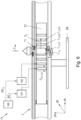
- FIG. 6 shows an example of a transport device 1 in the form of a long stator linear motor (LLM) 10 for moving transport units T 1 , ..., T k .
- the LLM 10 consists of a plurality of separate stator segments S 1 , ..., S p , of which only the segment S 1 with the transport unit T 1 is shown in Fig. 6 .
- the mechanical body of a transport unit T 1 corresponds to a drive body Ja, according to the invention.
- stator segments S 1 , ..., S p are usually assembled to form a stationary long stator 2.
- the stator segments S 1 , ..., S p can for this purpose be arranged on a stationary support structure SK.
- the stator segments S 1 , ..., S p can be designed in different geometric shapes, e.g., as straight segments or curved segments, in order to realize different transport paths.
- Electrical drive coils L m1 , ..., L mn are arranged along the long stator 2 in a known manner for each stator segment Sm in the longitudinal direction (shown in Fig. 6 only for the stator segment S 1 , n is an integer greater than one), which interact with drive magnets Y 1 , ..., Y L of the transport units T 1 , ..., T k .
- a drive force F A for each of the transport units T 1 , ..., T k is generated by controlling/setting coil voltages U L1 , ..., U Ln dropping across the drive coils L m1 , ..., L mn , in order to move the transport units T 1 , ..., T k and the drive bodies J A1 , ..., J Ak linked to them along the long stator 2.
- a plurality of drive coils L m1 , ..., L mn act simultaneously on a transport unit T 1 , ..., T k , which together generate the drive force FA.
- each coil voltage U L1 , ..., U Ln of each drive coil L m1 , ..., L mn in each stator segment S m is controlled by a coil control unit 101, 102, wherein a plurality of coil control units 101, 102 can also be combined into one control unit.
- Possible implementations of a coil control unit 101, 102 include microprocessor-based hardware, such as microcontrollers and integrated circuits (ASIC, FPGA).
- the system of drive magnets Y 1 , ..., Y L and drive coils L m1 , ..., L mn arranged on the long stator 2 forms an actuator A which converts a manipulated variable Fs required by a controller R, preferably by a position controller R, for the controlled movement of a transport unit T 1 into a drive force F A moving the transport unit T 1 .
- each of the transport units T 1 , ... , T k can be moved individually (speed, acceleration, path, direction) and independently (except for the avoidance of possible collisions) of the other transport units T 1 , ..., T k by means of a transport controller 100 that is superordinate to the coil control units 101, 102.
- the transport controller 100 can continuously predefine a position specification (equivalently also a speed specification) for each transport unit T 1 , ..., T k to be moved, which is converted by the coil control units 101, 102 into coil voltages U L11 , ..., U Lpn required for the movement of the transport unit T 1 , ..., T k .
- the coil control units 101, 102 receive set points SG 1 , ..., SG n for the control from the transport control 100, which can in particular be corresponding target positions x soll , or corresponding target speeds v soll . Since this basic principle of an LLM is sufficiently well known, it will not be discussed in detail here.
- the transport control 100 in particular the blocks position controller R x and pilot control unit V discussed with reference to Fig. 1 and Fig. 4 can be implemented.
- FIG. 7 shows four sequential scenarios a), b), c), and d).
- scenario a the transport unit T 1 and thus the drive body Ja, moves in the coordinate direction xR with a decreasing speed v towards a specified target position x soll (to the left).
- scenario b the upper side OS of the long stator 2 is subject to a large friction ⁇ 1 , which holds back the drive body J A .
- so-called V-rollers or V-groove guide rollers are often attached to the upper sides, which often lead to increased friction.
- a position sensor is attached at a selected and arbitrary point, e.g., in the geometric center of the transport unit T 1 - for example, a magnetoresistive AMR sensor well known from the prior art. If a position x given in the middle of the transport unit T 1 is now recorded as a movement variable BG and converted into a standstill set point B soll specified as a target position x soll , but a part, facing the upper side OS, of the transport unit T 1 is held back due to friction forces, the transport unit T 1 tilts, as shown in scenario b).
- the transport unit T 1 or the mechanical part of the transport unit T 1 i.e., the drive body J A , is twisted, which leads to undesired stored potential energy and the associated disadvantages.
- scenario c) after the transport unit T 1 has come to a standstill, an activation manipulated variable u akt is switched on, whereby the transport unit T 1 is set into vibration, the said potential energy is removed from the system by averaging effects, and the tilting in question is resolved.
- scenario d) in which the transport unit T 1 is in the specified target position x soll , in the x-direction xR, but the tilting described is eliminated.
- a tilting as described in scenarios a), b), c), and d) of Fig. 7 does not manifest itself in the direction of movement xR, but, rather, in a direction of movement yR that differs from the direction of movement xR, e.g., when a point on the upper side OS on the transport unit T 1 lies above or below a target value y soll specified for this point in the coordinate direction yR, the following procedure can be used to handle such cases in the context of this invention.
- the activation manipulated variable u akt only be determined and used to change the setting manipulated variable us if a magnitude of a second position deviation e y between the determined second position y and a second target position y soll specified for the second position y is above a specified second position threshold value y min , so that, in the present case of the LLM 10 shown in Fig. 6 and Fig. 7 , intervention is only carried out if a tilting as discussed above is present.
Landscapes
- Engineering & Computer Science (AREA)
- Physics & Mathematics (AREA)
- General Physics & Mathematics (AREA)
- Automation & Control Theory (AREA)
- Human Computer Interaction (AREA)
- Manufacturing & Machinery (AREA)
- General Engineering & Computer Science (AREA)
- Mechanical Engineering (AREA)
- Control Of Position Or Direction (AREA)
Applications Claiming Priority (1)
| Application Number | Priority Date | Filing Date | Title |
|---|---|---|---|
| AT505112023 | 2023-06-28 |
Publications (1)
| Publication Number | Publication Date |
|---|---|
| EP4485103A1 true EP4485103A1 (de) | 2025-01-01 |
Family
ID=91670479
Family Applications (1)
| Application Number | Title | Priority Date | Filing Date |
|---|---|---|---|
| EP24184244.2A Withdrawn EP4485103A1 (de) | 2023-06-28 | 2024-06-25 | Stillstandssteuerung mit manipulierter variabler vorwärtssteuerung |
Country Status (3)
| Country | Link |
|---|---|
| US (1) | US20250004440A1 (de) |
| EP (1) | EP4485103A1 (de) |
| CN (1) | CN119225437A (de) |
Citations (6)
| Publication number | Priority date | Publication date | Assignee | Title |
|---|---|---|---|---|
| EP0473914A2 (de) | 1990-08-16 | 1992-03-11 | Robert Bosch Gmbh | System zur Regelung eines Stellwerks in einem Kraftfahrzeug |
| US20060071625A1 (en) * | 2003-07-29 | 2006-04-06 | Hiroyuki Nakata | Robot arm control method and control device |
| US20070260356A1 (en) * | 2003-05-22 | 2007-11-08 | Abb Ab | Control Method for a Robot |
| JP5299255B2 (ja) * | 2009-03-18 | 2013-09-25 | 株式会社デンソーウェーブ | ロボット制御装置 |
| DE102019133025A1 (de) | 2019-12-04 | 2021-06-10 | Zf Automotive Germany Gmbh | Verfahren zur Positionsregelung für ein Lenksystem |
| EP3958446A1 (de) | 2020-08-21 | 2022-02-23 | Schneider Electric Industries SAS | Linearmotorsystem und betriebsverfahren für ein solches |
Family Cites Families (2)
| Publication number | Priority date | Publication date | Assignee | Title |
|---|---|---|---|---|
| US8602170B2 (en) * | 2007-11-14 | 2013-12-10 | Inventio Ag | Multiple brake device for elevator with monitoring |
| JP2021090343A (ja) * | 2019-12-03 | 2021-06-10 | ベーウントエル・インダストリアル・オートメイション・ゲゼルシャフト・ミト・ベシュレンクテル・ハフツング | 安全機能 |
-
2024
- 2024-06-25 CN CN202410829286.8A patent/CN119225437A/zh active Pending
- 2024-06-25 EP EP24184244.2A patent/EP4485103A1/de not_active Withdrawn
- 2024-06-26 US US18/755,171 patent/US20250004440A1/en active Pending
Patent Citations (6)
| Publication number | Priority date | Publication date | Assignee | Title |
|---|---|---|---|---|
| EP0473914A2 (de) | 1990-08-16 | 1992-03-11 | Robert Bosch Gmbh | System zur Regelung eines Stellwerks in einem Kraftfahrzeug |
| US20070260356A1 (en) * | 2003-05-22 | 2007-11-08 | Abb Ab | Control Method for a Robot |
| US20060071625A1 (en) * | 2003-07-29 | 2006-04-06 | Hiroyuki Nakata | Robot arm control method and control device |
| JP5299255B2 (ja) * | 2009-03-18 | 2013-09-25 | 株式会社デンソーウェーブ | ロボット制御装置 |
| DE102019133025A1 (de) | 2019-12-04 | 2021-06-10 | Zf Automotive Germany Gmbh | Verfahren zur Positionsregelung für ein Lenksystem |
| EP3958446A1 (de) | 2020-08-21 | 2022-02-23 | Schneider Electric Industries SAS | Linearmotorsystem und betriebsverfahren für ein solches |
Non-Patent Citations (1)
| Title |
|---|
| TAKAHASHI I ET AL: "High resolution position control under 1 sec. of an induction motor with full digitized methods", INDUSTRY APPLICATIONS SOCIETY ANNUAL MEETING, 1989., CONFERENCE RECORD OF THE 1989 IEEE, IEEE, 1 October 1989 (1989-10-01), pages 632 - 638vol.1, XP032143972, DOI: 10.1109/IAS.1989.96715 * |
Also Published As
| Publication number | Publication date |
|---|---|
| CN119225437A (zh) | 2024-12-31 |
| US20250004440A1 (en) | 2025-01-02 |
Similar Documents
| Publication | Publication Date | Title |
|---|---|---|
| Kiong et al. | Precision motion control: design and implementation | |
| CN109217616B (zh) | 用于运行运输装置的方法及其应用和运输装置及其应用 | |
| Sun et al. | Dual-motor coordination for high-quality servo with transmission backlash | |
| Meckl et al. | Experimental evaluation of shaped inputs to reduce vibration for a cartesian robot | |
| Erkorkmaz et al. | High bandwidth control of ball screw drives | |
| Khan et al. | Speed control of DC motor under varying load using PID controller | |
| JP2012516446A (ja) | 電磁アクチュエータの適応制御のための装置、制御器、及び方法 | |
| CN113646131B (zh) | 具有多重振动检测的机床中的振动衰减 | |
| KR102248547B1 (ko) | 1차 데드비트 관측기를 이용한 위치 제어 시스템 및 제어방법 | |
| Renton et al. | Motion control for linear motor feed drives in advanced machine tools | |
| EP0401018A2 (de) | Hochpräzises Positioniersystem | |
| Dong et al. | An experimental investigation of the effects of the compliant joint method on feedback compensation of pre-sliding/pre-rolling friction | |
| Smith et al. | Adaptive control strategies for a precision machine tools axis | |
| US20250004440A1 (en) | Standstill control with manipulated variable feedforward | |
| KR102410575B1 (ko) | 리니어 모터 스테이지의 제어 방법 및 제어 장치 | |
| Ro et al. | Nonlinear micro-dynamic behavior of a ball-screw driven precision slide system | |
| US20240151279A1 (en) | Method for standstill control of a multi-body system | |
| EP2752718B1 (de) | Aktuatorsteuervervahren und aktuatorsteuervorrichtung | |
| Xiong et al. | Modified internal model control scheme for the drive part with elastic joints in robotic system | |
| Qingding et al. | Robust fuzzy variable structure control of PMLSM servo system | |
| Park et al. | Energy-efficient PM-flux-based sensorless soft landing control for binary electromagnetic actuator | |
| US20040172171A1 (en) | Control structure for the active damping of low-frequency oscillations in numerically controlled machine tools | |
| Kuo et al. | Precision Position Control of a Permanent Magnet Linear Synchronous Motor Using Advanced PID Control | |
| CN110998462B (zh) | 用于机器元件的直接/间接混合驱动的调节器结构 | |
| Weiß et al. | Optimization of Motion Control for a Variably Excited Linear Hybrid Stepper Motor |
Legal Events
| Date | Code | Title | Description |
|---|---|---|---|
| PUAI | Public reference made under article 153(3) epc to a published international application that has entered the european phase |
Free format text: ORIGINAL CODE: 0009012 |
|
| STAA | Information on the status of an ep patent application or granted ep patent |
Free format text: STATUS: THE APPLICATION HAS BEEN PUBLISHED |
|
| AK | Designated contracting states |
Kind code of ref document: A1 Designated state(s): AL AT BE BG CH CY CZ DE DK EE ES FI FR GB GR HR HU IE IS IT LI LT LU LV MC ME MK MT NL NO PL PT RO RS SE SI SK SM TR |
|
| STAA | Information on the status of an ep patent application or granted ep patent |
Free format text: STATUS: THE APPLICATION IS DEEMED TO BE WITHDRAWN |
|
| 18D | Application deemed to be withdrawn |
Effective date: 20250702 |