EP4485105A1 - System und verfahren zur überwachung von defekten von industriell bearbeiteten plattenkanten und entsprechender industriell bearbeiteter werkzeugmaschine - Google Patents
System und verfahren zur überwachung von defekten von industriell bearbeiteten plattenkanten und entsprechender industriell bearbeiteter werkzeugmaschine Download PDFInfo
- Publication number
- EP4485105A1 EP4485105A1 EP24183277.3A EP24183277A EP4485105A1 EP 4485105 A1 EP4485105 A1 EP 4485105A1 EP 24183277 A EP24183277 A EP 24183277A EP 4485105 A1 EP4485105 A1 EP 4485105A1
- Authority
- EP
- European Patent Office
- Prior art keywords
- edge
- panel
- measuring device
- machine tool
- control unit
- Prior art date
- Legal status (The legal status is an assumption and is not a legal conclusion. Google has not performed a legal analysis and makes no representation as to the accuracy of the status listed.)
- Pending
Links
Images





Classifications
-
- G—PHYSICS
- G05—CONTROLLING; REGULATING
- G05B—CONTROL OR REGULATING SYSTEMS IN GENERAL; FUNCTIONAL ELEMENTS OF SUCH SYSTEMS; MONITORING OR TESTING ARRANGEMENTS FOR SUCH SYSTEMS OR ELEMENTS
- G05B19/00—Program-control systems
- G05B19/02—Program-control systems electric
- G05B19/418—Total factory control, i.e. centrally controlling a plurality of machines, e.g. direct or distributed numerical control [DNC], flexible manufacturing systems [FMS], integrated manufacturing systems [IMS] or computer integrated manufacturing [CIM]
- G05B19/41875—Total factory control, i.e. centrally controlling a plurality of machines, e.g. direct or distributed numerical control [DNC], flexible manufacturing systems [FMS], integrated manufacturing systems [IMS] or computer integrated manufacturing [CIM] characterised by quality surveillance of production
-
- G—PHYSICS
- G05—CONTROLLING; REGULATING
- G05B—CONTROL OR REGULATING SYSTEMS IN GENERAL; FUNCTIONAL ELEMENTS OF SUCH SYSTEMS; MONITORING OR TESTING ARRANGEMENTS FOR SUCH SYSTEMS OR ELEMENTS
- G05B2219/00—Program-control systems
- G05B2219/30—Nc systems
- G05B2219/32—Operator till task planning
- G05B2219/32177—Computer assisted quality surveyance, caq
-
- G—PHYSICS
- G05—CONTROLLING; REGULATING
- G05B—CONTROL OR REGULATING SYSTEMS IN GENERAL; FUNCTIONAL ELEMENTS OF SUCH SYSTEMS; MONITORING OR TESTING ARRANGEMENTS FOR SUCH SYSTEMS OR ELEMENTS
- G05B2219/00—Program-control systems
- G05B2219/30—Nc systems
- G05B2219/32—Operator till task planning
- G05B2219/32182—If state of tool, product deviates from standard, adjust system, feedback
-
- G—PHYSICS
- G05—CONTROLLING; REGULATING
- G05B—CONTROL OR REGULATING SYSTEMS IN GENERAL; FUNCTIONAL ELEMENTS OF SUCH SYSTEMS; MONITORING OR TESTING ARRANGEMENTS FOR SUCH SYSTEMS OR ELEMENTS
- G05B2219/00—Program-control systems
- G05B2219/30—Nc systems
- G05B2219/45—Nc applications
- G05B2219/45174—Making panels
Definitions
- This solution relates to a system and a method for monitoring defects of industrially-processed panel edges and to a corresponding industrial-processing machine tool.
- the edging process comprises operations aimed at coating/ennobling the lateral surfaces of the panels and is carried out, on an industrial level, with automatic or semi-automatic machine tools, called edgebanding machines, by applying edges made of various types of materials (for example plastic, wood, cellulose, metal), which are generally glued with hot-melt adhesives.
- edgebanding machines automatic or semi-automatic machine tools, called edgebanding machines, by applying edges made of various types of materials (for example plastic, wood, cellulose, metal), which are generally glued with hot-melt adhesives.
- the edging can comprise, for example, the following operations (of known type and not described in detail herein): grinding of the panel; application of the glue and heating of the edge; application of the edge; heading; rough-milling; smoothing/trimming; scraping of the edge and of the glue; brushing; dressing.
- Figure 1 shows a panel 1, for example a wooden panel, having a first and a second main extension surface S 1 , S 2 (in a horizontal plane xy in the reference system indicated in Figure 1 ) and lateral surfaces S L , which laterally delimit the panel 1 (in particular, two longitudinal surfaces, in the plane xz, and two transverse surfaces, in the plane yz of the reference system of Figure 1 ) .
- the panel 1 is provided with an edge 2, having been applied, by means of the aforementioned edging operations, to one of the longitudinal surfaces, to coat/ennoble the appearance of the respective lateral surface.
- the panels resulting from the aforementioned edging operations may feature "edging defects", i.e. anomalies present on the edged panel with respect to an expected result.
- Such edging defects may include, for example, one or more of the following errors: parallelism errors; linearity errors; radius errors; squaring errors; shaping errors; splintering; orange peel; slivers; thickness errors; heading errors; excess errors, etc.
- Figure 2A shows a panel, again indicated with number 1, which has a squaring error in the plane yz;
- Figure 2B shows a panel 1 with a radius error in the plane xy;
- Figure 2C shows a panel 1 with shaping defects;
- Figure 2D shows a panel 1 with excess defects in the plane yz.
- the panels may not meet both aesthetic specifications (for example, from the point of view of pleasantness to the eye or touch) and functional specifications (for example, with regard to the ability of the edge to effectively adhere to the panel).
- aesthetic specifications for example, from the point of view of pleasantness to the eye or touch
- functional specifications for example, with regard to the ability of the edge to effectively adhere to the panel.
- a properly applied edge makes the panel mechanically more resistant over time, when subjected to external agents such as humidity and operating temperatures.
- the object of this solution is to at least partly solve the problems discussed above and to fulfil the aforementioned need.
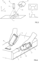
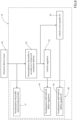
- a panel edge defect monitoring system As schematically shown in Figure 3 , a panel edge defect monitoring system, indicated in general with 10, comprises a measuring device 12, configured to perform a dimensional measurement of a section of an edge-panel system, wherein the edge-panel system, indicated with 14, is the assembly consisting of a portion of a panel, indicated again with 1, and of an edge, indicated again with 2, applied on said portion, as a closing element of a corresponding lateral surface of the panel 1, applied by means of an edging process.
- the measuring device 12 can be configured to perform a detection of the three-dimensional pattern of the outer surface of the edge-panel system 14.
- the measuring device 12 is configured to perform a profile measurement, for detecting a profile of the section of the edge-panel system 14.
- the measuring device 12 is made in a casing 12', of a portable type, being operable by a user to perform the aforementioned dimensional/profile measurement.
- a casing 12' of a portable type, being operable by a user to perform the aforementioned dimensional/profile measurement.
- different ways of implementing the same measuring device 12 can be envisaged.
- the profile measured by the measuring device 12 corresponds to a section of the edge-panel system 14 in the plane yz (in the example, transverse to the longitudinal extension of the panel 1); however, it is underlined that the same measuring device 12 can be operated to measure different profiles, relating to different sections of the edge-panel system 14.
- the monitoring system 10 further comprises a control unit 16, operatively coupled to the measuring device 12 and configured to receive dimensional measurement data from the measuring device 12, in particular data associated with the aforesaid profile, deriving from the measurements carried out, and to process said dimensional measurement data to determine information concerning the presence of defects associated with the aforesaid edge-panel system 14.
- a control unit 16 operatively coupled to the measuring device 12 and configured to receive dimensional measurement data from the measuring device 12, in particular data associated with the aforesaid profile, deriving from the measurements carried out, and to process said dimensional measurement data to determine information concerning the presence of defects associated with the aforesaid edge-panel system 14.
- control unit 16 is configured to determine defect indicators or indices, which characterize the measured profile of the edge-panel system 14.
- defect indicators can, for example, be associated with (without being limited to the following list): parallelism errors; linearity errors; radius errors; squaring errors; shaping errors; splintering; orange peel; slivers; thickness errors; heading errors; excess errors, etc.
- control unit 16 is configured to provide, for example through wireless communication, the processed information concerning the presence of defects associated with the aforesaid edge-panel system 14 (for example, the aforesaid defect indicators) to a machine tool 20, for example a numerical control machine, which performed the edging operations for the manufacturing of the edge 2.
- This machine tool 20 can thus optimize, based on the same information (used as a feedback), processing parameters for processing of the panels 1 and the corresponding edges 2, in order to reduce processing errors and processing waste and/or non-compliant products.
- the machine tool 20, provided - in a known manner - with a respective controller 21 will also be able to determine, based on the aforementioned information concerning the presence of defects associated with the edge-panel system 14, solutions for ordinary or extraordinary maintenance of the same machine tool 20.
- a respective controller 21 for example a PLC, Programmable Logic Controller
- the machine tool 20 in particular designed for processing of wood panels, may, for example, comprise an oblong base provided with longitudinal guide members parallel to a first, substantially horizontal, direction; a plurality of cross members mounted between the longitudinal guide members parallel to a second, substantially horizontal, direction, which is transverse to the first direction; and at least one support block mounted on each cross member to hold at least one panel (not shown herein).
- the processing machine 20 is further provided with an overhead crane, which is movable along the base in the first direction, extends above the base in the second direction and normally supports at least one processing head provided with a tool (not shown herein) for processing of the panels (for example, to perform the aforementioned edging operation).
- the control unit 16 (or the machine tool 20, through the respective controller 21) will also be able to carry out, based on the same information concerning the presence of defects of the edge-panel system 14, assessments regarding the quality of the semi-finished products used, including for example: the edge 2, the panel 1, the glue used, again in order to reduce processing errors and processing waste and/or non-compliant products.
- control unit 16 is implemented by means of a processing unit separate from the measuring device 12 and from the machine tool 20
- the same control unit 16 could alternatively be realized within the measuring device 12, in an integrated manner; or it could be part of the controller 21 of the machine tool 20; or still it could be realized remotely, for example by means of a cloud server.
- the measuring device 12, the aforesaid control unit 16 and the machine tool 20 (and the respective controller 21) can be part of an IoT (Internet of Things) platform or network, schematically indicated with 22, comprising for example a cloud storage unit, for implementing a two-way communication and storage of the information concerning the monitoring operations (including the aforesaid information concerning the presence of defects, the aforesaid assessments about the quality of the products used, the aforesaid determinations of ordinary or extraordinary maintenance).
- IoT Internet of Things
- the information concerning the monitoring operations including the aforesaid information concerning the presence of defects, the aforesaid assessments about the quality of the products used, the aforesaid determinations of ordinary or extraordinary maintenance.
- this IoT network 22 may create relationships between the defect indicators and/or the machine parameters and/or the processing conditions (in terms of machine type, machine operator, environmental conditions, edge type, panel type, tool type, processing parameters) through "data analytics" techniques. These relationships can, for example (but not limitedly to this example), be useful to an operator to keep the production process under control, to suggest optimal processing conditions to the machine tool 20 upon first set-up, if these have occurred in the past based on previous experiences (heuristic knowledge); and also to a manufacturer of the machine tool 20 to classify the performances of its machine fleet.
- the measuring device 12 can be provided with a starting element 26, for example in the form of a turn-on button, configured so as to start the operation of the measuring device 12.
- the measuring device 12 (or the aforementioned control unit 16) can be configured, after operations have started, to verify the presence and compliance with predetermined measurement conditions, for example in relation to a correct positioning of the measuring device 12 with respect to the object under analysis (the aforementioned edge-panel system 14).
- the measuring device 12 can, for example, be provided with a position sensor (not shown), in order to determine a position with respect to the edge-panel system 14; and compliance with the measuring conditions can be determined if the position measured by the position sensor fulfils a given condition, for example is lower than a given threshold.
- a position sensor not shown
- the measuring device 12 can be provided with a user interface, HMI (Human Machine Interface) 28, provided with input elements, for example buttons or keys, and with a display, which can be configured to provide an indication (for example, a visual or audible indication) as to whether the aforesaid measuring conditions are respected.
- HMI Human Machine Interface
- the measuring device 12 (or the aforementioned control unit 16) can be configured to determine the activation of the measurement functions concerning the surface to be detected and subsequent provision of the measurement data to the controller 21 of the machine tool 20, only if compliance with the aforesaid measurement conditions is determined.
- the measuring device 12 performs a contactless measurement, at a certain distance from the edge-panel system 14.
- the aforementioned measuring device 12 is instead configured to perform a measurement in contact with the aforementioned edge-panel system 14.
- the measuring device 12 comprises a coupling element 29, which can properly be shaped or made so as to be coupled to the outer profile of the edge-panel system 14, for carrying out the dimensional measurements.
- This coupling element 29 can therefore facilitate the alignment of the measuring device 12 with the edge-panel system 14 and, hence, the correct positioning of the measuring device 12 for the execution of the dimensional/profile measurements.
- the aforementioned measuring device 12 can entail the use of various types of surface/profile measuring systems, for example (but not limited to the following list):
- a possible embodiment for the measuring device 12, shown in Figure 5 is based on a laser line triangulation system.
- the measuring device 12 comprises, in this case: a laser line projector 30, having a first optical axis A1; and a camera 32 with a second optical axis A2, inclined at a given angle ⁇ with respect to the first optical axis A1 of the projector 30.
- the control unit 16 associated with the measuring device 12 is, in this case, configured to process the image acquired by the camera 32 and extract the profile of the section (in the example, in the plane yz) of the edge-panel system 14 illuminated by the laser line.
- the measuring device 12 and/or the control unit 16 may further comprise an interface configured to receive characteristics of the panel 2 to be investigated. These characteristics may be, for example and without be exhaustive:
- the measuring device 12 may comprise a barcode or QR code reader for this purpose, so as to read an identification code present on the edge-panel system 14 and automatically acquire, for example upon pressing of a dedicated button 26', the aforementioned characteristics of the panel 2, appropriately encoded in the code.
- the monitoring system 10 may comprise a separate apparatus 33 for reading the aforementioned barcode and/or QR code (or the like), suitably coupled to the measuring device 12 and/or to the control unit 16, so as to provide the information requested for optimization of the measurement of the measuring device 12 and/or of the implementation of the algorithms for determining the defect indicators by the control unit 16.
- the aforementioned control unit 16 can therefore comprise a first interface for receiving the measurement data sent by the measuring device 12; and also a second interface for receiving the characteristics of the panel 2 to be investigated (and/or of the machine tool 20).
- the two interfaces may coincide.
- the aforementioned second interface can be configured to receive the characteristics of the panel 2 from an operator, who can directly interact with the aforementioned control unit 16 or with the controller 21 of the machine tool 20.
- the operator can also define tolerances of acceptability of the defects that can characterize the edging process, depending on the performances of the machine tool 20.
- control unit 16 may further comprise:
- the control unit 16 may further comprise a first output interface, configured to be coupled to and communicate with the controller 21 of the machine tool 20, for the transfer of the new configuration and processing parameters to the machine tool 20; and, furthermore, a second output interface, forming part of a human-machine interface (comprising at least one displaying element or display), where the results of the processing can be shown, including the aforementioned indicators describing the defects of the edging process, requests of maintenance for the machine tool 20, assessments on the quality of the semi-finished products.
- a first output interface configured to be coupled to and communicate with the controller 21 of the machine tool 20, for the transfer of the new configuration and processing parameters to the machine tool 20
- a second output interface forming part of a human-machine interface (comprising at least one displaying element or display), where the results of the processing can be shown, including the aforementioned indicators describing the defects of the edging process, requests of maintenance for the machine tool 20, assessments on the quality of the semi-finished products.
- This procedure comprises, step 40, the preparation of the measuring device 12 and, for example, the appropriate positioning of the measuring device 12 with respect to the edge-panel system 14.
- the measuring device 12 is then started, step 42, for example by means of the corresponding starting element 26 (or, alternatively, by means of an external trigger, received for example from the controller 21 of the machine tool 20).
- the procedure can then entail the definition of the characteristics of the panel 2 to be investigated (and/or of the machine tool 20), for example by means of the aforementioned reading of barcode and/or QR code information by means of the measuring device 12 or by means of the separate apparatus 33. These characteristics can also be sent to the control unit 16.
- the measuring device 12 can then verify the existence of the measuring conditions and, only in the case of a positive outcome, start the procedure for measuring the dimensional characteristics of the panel 2, step 43.
- the measuring device can measure the profile of a section of the edge-panel system 14.
- the measurement data is then sent, step 44, to the control unit 16, which automatically processes the acquired data, step 45, in order to determine the information concerning the defects of the edging process, including, in particular, the defect indications (or indices).
- the profile of the section of the edge-panel system 14 can be displayed by means of the user interface 28.
- the information concerning the defects can be provided to a user, through visual feedback or feedback of other nature, as shown in step 47.
- indications can be provided about the nature and acceptability of the processed defects; in case of defect indices that do not guarantee the requested tolerances of acceptability, the control unit 16 can, for example, suggest an automatic redefinition of the processing parameters and/or the execution of maintenance for the machine tool 20.
- control unit 16 can provide the controller 21 of the machine tool 20 with information concerning the detected defects, in order, for example, to modify processing parameters implemented by the same machine tool 20.
- the control unit 16, if required, can directly provide the controller 21 of the machine tool 20 with configuration/processing parameters properly modified according to the detected defects.
- the automatic processing of the measurement data by the control unit 16 can entail the application of traditional algorithms, namely based on the determination of output data by means of predetermined relationships with the input data; or of artificial intelligence algorithms, for example based on decision trees or neural networks.
- Figure 8 shows a possible algorithm (of a traditional type, namely not based on artificial intelligence) that can be implemented by the aforementioned stage for calculating the defect indicators to calculate a "radius” defect indicator; and also a "square" defect indicator in the plane yz.
- This algorithm entails receiving the measurement data, step 50, in particular the aforementioned profile of the section of the edge-panel system 14, detected by the measuring device 12; this profile can also be displayed by the control unit 16 through the corresponding user interface 28, as shown in step 51.
- a step, denoted with 52, is carried out involving the rotation-translation of the profile in accordance with a predefined coordinate system.
- step 53 by means of a first system of mathematical/geometric relationships, which is not described in detail herein, a first defect index, in the example a radius index, can be calculated.
- This first defect index can further be displayed by means of the user interface 28, step 54.
- step 55 by means of a second system of mathematical/geometric relationships, which is also not described in detail, a second defect index can be calculated, in the example a squaring error in the plane yz.
- This second defect index can further be displayed by means of the user interface 28, step 56.
- This algorithm can entail, similarly to what discussed above, receiving the measurement data, here shown at step 60, in particular the aforementioned profile of the section of the edge-panel system 14; this profile can also be displayed by the control unit 16 through the corresponding user interface 28, as shown in step 61.
- the algorithm then proceeds with the application of a trained artificial intelligence model, step 62, capable of extracting, step 64, classes of the defect indices of the profile of the section of the edge-panel system 14, in particular for the determination of the aforementioned defect indices, which can be displayed by means of the aforementioned user interface 28, step 65.
- a trained artificial intelligence model step 62, capable of extracting, step 64, classes of the defect indices of the profile of the section of the edge-panel system 14, in particular for the determination of the aforementioned defect indices, which can be displayed by means of the aforementioned user interface 28, step 65.
- the procedure entails a training step, denoted with 66, for training the artificial intelligence model, not only based on training data, but also based on the results of the measurements, by means of appropriate feedback, as indicated in step 68.
- this feedback can be a function of a correlation between an expected output and an actually recorded output, for example in the form of a root of the mean squared error.
- the training step can entail the training of a plurality of artificial intelligence models, indicated with M 1 ...M n , one for each one of the defect indices to be measured (for example a radius index, a squaring error index, etc.), which are properly trained by means of training data and of a comparison between the measurements and the expected target.
- This training may also require the operator to provide a classification of the identified defects and of the measured panel assessment indices, using the aforementioned user interface 28.
- the described solution provides an effective automated system for monitoring defects of an edge-panel system, based on a profile measurement, extracting the (dimensional, geometric) profile of a section of the edge-panel system, for the subsequent calculation of the defect indicators that characterise the measured profile.
- these indices can be used to carry out various controls and actions, including, but not limited to:
- the system also advantageously provides feedback to an operator through a human-machine interface, which can, for example, indicate if minimum test conditions are respected, for example if the object under analysis is positioned and oriented correctly with respect to the measuring device and is placed at the right distance; the measurement can advantageously be carried out only if the previous feedback has given a positive result (for example, only if the object under analysis has been positioned and oriented correctly with respect to the measuring device and is placed at the right distance).
- the system also allows measurement to be carried out on different materials and also with different colours, transparency, texture, dimensions, etc., being able to automatically adjust the parameters of the system, for example by means of the aforementioned operation of reading of a barcode (or similar identification code) applied on the panel.
- a barcode or similar identification code
- the integration of the measuring device, of the control unit and of the processing machine tool in an IoT network is also advantageous.
- the measuring device 12 could be fixed (non-portable) and external to the machine tool 20, as schematically shown in Figure 10 ; or it could be integrated in the machine tool 20, downstream and/or upstream of the corresponding processing units used for the panel 1, as schematically shown in Figure 11 ; or still it could be moved by a robot 70 or a similar automated actuator element, as schematically shown in Figure 12 .
- the defect monitoring operations could also be performed in real time, during processing of the panels 1 by the machine tool 20.
- a further aspect of this solution can entail the use of a reference sample 80, having a precisely known profile, by way of example shown in Figure 13 , which allows periodic checks to be carried out on the correspondence of the measured data with expectations.
- the use of this reference sample 80 allows to avoid drifts of the measuring instrument between one calibration and the next one.
- the result of the performed check can be viewed through the user interface 28 or the control unit 16.
Landscapes
- Engineering & Computer Science (AREA)
- General Engineering & Computer Science (AREA)
- Manufacturing & Machinery (AREA)
- Quality & Reliability (AREA)
- Physics & Mathematics (AREA)
- General Physics & Mathematics (AREA)
- Automation & Control Theory (AREA)
- General Factory Administration (AREA)
Applications Claiming Priority (1)
| Application Number | Priority Date | Filing Date | Title |
|---|---|---|---|
| IT202300013398 | 2023-06-28 |
Publications (1)
| Publication Number | Publication Date |
|---|---|
| EP4485105A1 true EP4485105A1 (de) | 2025-01-01 |
Family
ID=88098191
Family Applications (1)
| Application Number | Title | Priority Date | Filing Date |
|---|---|---|---|
| EP24183277.3A Pending EP4485105A1 (de) | 2023-06-28 | 2024-06-20 | System und verfahren zur überwachung von defekten von industriell bearbeiteten plattenkanten und entsprechender industriell bearbeiteter werkzeugmaschine |
Country Status (1)
| Country | Link |
|---|---|
| EP (1) | EP4485105A1 (de) |
Citations (3)
| Publication number | Priority date | Publication date | Assignee | Title |
|---|---|---|---|---|
| CN211615960U (zh) * | 2019-12-12 | 2020-10-02 | 电子科技大学中山学院 | 基于视觉识别的木材封边设备 |
| US20210157310A1 (en) * | 2018-08-12 | 2021-05-27 | Skf Ai, Ltd. | System and method for forecasting industrial machine failures |
| US20230064767A1 (en) * | 2020-02-12 | 2023-03-02 | Homag Gmbh | Method and device for identifying workpieces |
-
2024
- 2024-06-20 EP EP24183277.3A patent/EP4485105A1/de active Pending
Patent Citations (3)
| Publication number | Priority date | Publication date | Assignee | Title |
|---|---|---|---|---|
| US20210157310A1 (en) * | 2018-08-12 | 2021-05-27 | Skf Ai, Ltd. | System and method for forecasting industrial machine failures |
| CN211615960U (zh) * | 2019-12-12 | 2020-10-02 | 电子科技大学中山学院 | 基于视觉识别的木材封边设备 |
| US20230064767A1 (en) * | 2020-02-12 | 2023-03-02 | Homag Gmbh | Method and device for identifying workpieces |
Non-Patent Citations (1)
| Title |
|---|
| CHEN LUN-CHI ET AL: "Edge-glued wooden panel defect detection using deep learning", WOOD SCIENCE AND TECHNOLOGY, SPRINGER VERLAG, BERLIN, DE, vol. 56, no. 2, 31 January 2022 (2022-01-31), pages 477 - 507, XP037751730, ISSN: 0043-7719, [retrieved on 20220131], DOI: 10.1007/S00226-021-01316-3 * |
Similar Documents
| Publication | Publication Date | Title |
|---|---|---|
| JP7550462B2 (ja) | 自動検査方法 | |
| CN111929309B (zh) | 一种基于机器视觉的铸造件外观缺陷检测方法及系统 | |
| US10922510B2 (en) | Method, automation system and computer system for detecting optical codes | |
| JP2002508071A (ja) | ボディ・シェルの表面欠陥を自動的に認識する方法およびこの方法を実施する装置 | |
| JP2019135638A (ja) | 生産プロセス中に異常なワークピースを自動検出するためのデータ駆動方法 | |
| CN105531214B (zh) | 用于跟踪片材中的缺陷的设备和方法 | |
| US20220147871A1 (en) | Method and system for quality control in industrial manufacturing | |
| Minnetti et al. | Smart portable laser triangulation system for assessing gap and flush in car body assembly line | |
| Iglesias et al. | Application of computer vision techniques to estimate surface roughness on wood-based sanded workpieces | |
| US12293511B2 (en) | Anomaly detection system in the automatic placement of composites during the manufacturing of structural elements | |
| CN112183919A (zh) | 质量预测系统和质量预测方法 | |
| CN118458461A (zh) | 物件的纠偏方法及纠偏装置 | |
| CN120314280A (zh) | 一种金刚石钻石粒高精度智能质检系统 | |
| EP4485105A1 (de) | System und verfahren zur überwachung von defekten von industriell bearbeiteten plattenkanten und entsprechender industriell bearbeiteter werkzeugmaschine | |
| CN104729423B (zh) | 一种用于检测异形玻璃几何参数的测量方法 | |
| CN210108267U (zh) | 橡胶半制品宽度尺寸在线检测装置 | |
| WO2019167012A1 (en) | System for measuring gap and flush | |
| US20250078248A1 (en) | In-process inspection for automated fiber placement | |
| CN120551757A (zh) | 一种农机变速箱的装配辅助防错系统及方法 | |
| EP3193158A1 (de) | System und verfahren zur beurteilung des visuellen erscheinungsbildes einer reflektierenden oberfläche | |
| CN114062198B (zh) | 乌氏黏度计自动检定系统及检定方法 | |
| KR20240069858A (ko) | 노즐의 분사 불량 검사 시스템 및 이를 이용한 노즐의 분사 불량 검사 방법 | |
| CN106197361B (zh) | 一种不锈钢板表面光洁度在线检测装置 | |
| Cavaliere et al. | Development of a system for the analysis of surface defects in die-cast components using machine vision | |
| KR20140065500A (ko) | 잔류 스케일 측정 장치 및 방법 |
Legal Events
| Date | Code | Title | Description |
|---|---|---|---|
| PUAI | Public reference made under article 153(3) epc to a published international application that has entered the european phase |
Free format text: ORIGINAL CODE: 0009012 |
|
| STAA | Information on the status of an ep patent application or granted ep patent |
Free format text: STATUS: THE APPLICATION HAS BEEN PUBLISHED |
|
| AK | Designated contracting states |
Kind code of ref document: A1 Designated state(s): AL AT BE BG CH CY CZ DE DK EE ES FI FR GB GR HR HU IE IS IT LI LT LU LV MC ME MK MT NL NO PL PT RO RS SE SI SK SM TR |
|
| STAA | Information on the status of an ep patent application or granted ep patent |
Free format text: STATUS: REQUEST FOR EXAMINATION WAS MADE |
|
| 17P | Request for examination filed |
Effective date: 20250627 |