EP4485553A1 - Lithiumergänzungsvorrichtung und lithiumergänzungsverfahren - Google Patents
Lithiumergänzungsvorrichtung und lithiumergänzungsverfahren Download PDFInfo
- Publication number
- EP4485553A1 EP4485553A1 EP22951504.4A EP22951504A EP4485553A1 EP 4485553 A1 EP4485553 A1 EP 4485553A1 EP 22951504 A EP22951504 A EP 22951504A EP 4485553 A1 EP4485553 A1 EP 4485553A1
- Authority
- EP
- European Patent Office
- Prior art keywords
- lithium
- regions
- calendering
- electrode plate
- fast roller
- Prior art date
- Legal status (The legal status is an assumption and is not a legal conclusion. Google has not performed a legal analysis and makes no representation as to the accuracy of the status listed.)
- Pending
Links
Images




Classifications
-
- H—ELECTRICITY
- H01—ELECTRIC ELEMENTS
- H01M—PROCESSES OR MEANS, e.g. BATTERIES, FOR THE DIRECT CONVERSION OF CHEMICAL ENERGY INTO ELECTRICAL ENERGY
- H01M4/00—Electrodes
- H01M4/02—Electrodes composed of, or comprising, active material
- H01M4/04—Processes of manufacture in general
-
- H—ELECTRICITY
- H01—ELECTRIC ELEMENTS
- H01M—PROCESSES OR MEANS, e.g. BATTERIES, FOR THE DIRECT CONVERSION OF CHEMICAL ENERGY INTO ELECTRICAL ENERGY
- H01M4/00—Electrodes
- H01M4/02—Electrodes composed of, or comprising, active material
- H01M4/04—Processes of manufacture in general
- H01M4/043—Processes of manufacture in general involving compressing or compaction
- H01M4/0435—Rolling or calendering
-
- H—ELECTRICITY
- H01—ELECTRIC ELEMENTS
- H01M—PROCESSES OR MEANS, e.g. BATTERIES, FOR THE DIRECT CONVERSION OF CHEMICAL ENERGY INTO ELECTRICAL ENERGY
- H01M10/00—Secondary cells; Manufacture thereof
- H01M10/04—Construction or manufacture in general
- H01M10/0404—Machines for assembling batteries
-
- H—ELECTRICITY
- H01—ELECTRIC ELEMENTS
- H01M—PROCESSES OR MEANS, e.g. BATTERIES, FOR THE DIRECT CONVERSION OF CHEMICAL ENERGY INTO ELECTRICAL ENERGY
- H01M10/00—Secondary cells; Manufacture thereof
- H01M10/04—Construction or manufacture in general
- H01M10/0431—Cells with wound or folded electrodes
-
- H—ELECTRICITY
- H01—ELECTRIC ELEMENTS
- H01M—PROCESSES OR MEANS, e.g. BATTERIES, FOR THE DIRECT CONVERSION OF CHEMICAL ENERGY INTO ELECTRICAL ENERGY
- H01M10/00—Secondary cells; Manufacture thereof
- H01M10/05—Accumulators with non-aqueous electrolyte
- H01M10/052—Li-accumulators
-
- H—ELECTRICITY
- H01—ELECTRIC ELEMENTS
- H01M—PROCESSES OR MEANS, e.g. BATTERIES, FOR THE DIRECT CONVERSION OF CHEMICAL ENERGY INTO ELECTRICAL ENERGY
- H01M4/00—Electrodes
- H01M4/02—Electrodes composed of, or comprising, active material
- H01M4/04—Processes of manufacture in general
- H01M4/0402—Methods of deposition of the material
- H01M4/0404—Methods of deposition of the material by coating on electrode collectors
-
- H—ELECTRICITY
- H01—ELECTRIC ELEMENTS
- H01M—PROCESSES OR MEANS, e.g. BATTERIES, FOR THE DIRECT CONVERSION OF CHEMICAL ENERGY INTO ELECTRICAL ENERGY
- H01M4/00—Electrodes
- H01M4/02—Electrodes composed of, or comprising, active material
- H01M4/04—Processes of manufacture in general
- H01M4/0402—Methods of deposition of the material
- H01M4/0409—Methods of deposition of the material by a doctor blade method, slip-casting or roller coating
-
- Y—GENERAL TAGGING OF NEW TECHNOLOGICAL DEVELOPMENTS; GENERAL TAGGING OF CROSS-SECTIONAL TECHNOLOGIES SPANNING OVER SEVERAL SECTIONS OF THE IPC; TECHNICAL SUBJECTS COVERED BY FORMER USPC CROSS-REFERENCE ART COLLECTIONS [XRACs] AND DIGESTS
- Y02—TECHNOLOGIES OR APPLICATIONS FOR MITIGATION OR ADAPTATION AGAINST CLIMATE CHANGE
- Y02E—REDUCTION OF GREENHOUSE GAS [GHG] EMISSIONS, RELATED TO ENERGY GENERATION, TRANSMISSION OR DISTRIBUTION
- Y02E60/00—Enabling technologies; Technologies with a potential or indirect contribution to GHG emissions mitigation
- Y02E60/10—Energy storage using batteries
Definitions
- the present application relates to the field of battery technology, in particular to a lithium supplementing apparatus and a lithium supplementing method.
- Energy saving and emission reduction is a key to the sustainable development of the automotive industry.
- the electric vehicle becomes an important part the sustainable development of the automobile industry due to its advantages of energy saving and environmental protection.
- the battery technology is another vital factor for its development.
- lithium supplementing can be performed on a battery, so as to supplement loss of active lithium during the use of the battery, thereby improving the service life of the battery; in addition, loss of active lithium during the first charging process of the battery can also be supplemented, thereby improving the energy density of the battery. Therefore, how to efficiently perform lithium supplementing on batteries becomes a problem to be solved.
- the present application provides a lithium supplementing apparatus and a lithium supplementing method, which can efficiently perform lithium supplementing on a battery.
- a lithium supplementing apparatus including: a plurality of calendering devices used for respectively transferring lithium on a plurality of lithium strips to a plurality of first regions distributed in a first direction on a coating device, the first direction being a width direction of a first electrode plate to be subjected to lithium supplementing; the coating device used for respectively coating lithium of the plurality of first regions on a plurality of second regions corresponding to the plurality of first regions on the first electrode plate; and a segmenting device used for segmenting the first electrode plate according to the plurality of second regions so as to form a plurality of segmented second electrode plates.
- lithium on a plurality of lithium strips is respectively transferred to a plurality of first regions distributed in the width direction of a electrode plate on a coating device at the same time, and the lithium in the plurality of first regions is transferred to a corresponding plurality of second regions on a first electrode plate by a coating device, and then a segmenting device segments the first electrode plate on the basis of the plurality of second regions, so as to form a plurality of segmented second electrode plates.
- the lithium supplementing efficiency is greatly improved.
- a calendering device includes calendering rollers
- a coating device includes a fast roller
- the lithium strips pass through between the fast roller and the calendering rollers, so that lithium on the lithium strips is transferred to the first regions corresponding to the lithium strips on the fast roller.
- roller systems are used to transfer lithium on the lithium strips to a coating device, in which each calendering device includes calendering rollers, and the coating device includes a fast roller; and by means of the relative movement between the calendering rollers and the fast roller, lithium on the lithium strips is transferred to the first regions corresponding to the lithium strips on the fast roller when the lithium strips pass through between the fast roller and the calendering rollers, which is easy to implement and has high reliability.
- a protective belt is provided between the lithium strips and the calendering rollers, the protective belt and the lithium strips pass through between the fast roller and the calendering rollers at the same time, and the protective belt is used for isolating the lithium strips from the calendering rollers.
- the protective belt can protect the lithium strips, so as to prevent the lithium strips from being damaged when passing through between the fast roller and the calendering rollers.
- the material of the protective belt is polyethylene terephthalate (PET), which is easy to acquire and has a low cost.
- the calendering device further includes back rollers, the calendering rollers are located between the back rollers and the fast roller, and the back rollers are used for providing a supporting force towards the fast roller for the calendering rollers.
- the size of the calendering rollers is generally smaller than that of the fast roller, when the calendering rollers and the fast roller move relative to each other, the side of the calendering rollers facing the fast roller may bear a relatively large pressure, which easily causes loss to the calendering rollers so as to affect the service life thereof.
- the pressure applied by the fast roller to the calendering rollers can be balanced, thereby protecting the calendering rollers.
- the calendering device further includes a scraper used for controlling the width of the lithium in the first regions on the fast roller in the first direction.
- a scraper used for controlling the width of the lithium in the first regions on the fast roller in the first direction.
- the coating device further includes a laminating roller, and the first electrode plate passes through between the fast roller and the laminating roller, so as to coat lithium in the first regions on the fast roller onto the second regions corresponding to the first regions on the first electrode plate.
- roller systems are used to transfer lithium on a coating device to a first electrode plate;
- the coating device further includes a laminating roller arranged opposite to a fast roller; by means of the relative movement between the laminating roller and the fast roller, the first electrode plate passes through between the fast roller and the laminating roller, so as to coat lithium in the first regions on the fast roller onto the second regions corresponding to the first regions on the first electrode plate, which is easy to implement and has high reliability.
- the lithium supplementing apparatus can simultaneously form a plurality of second electrode plates with different widths after being subjected to lithium supplementing, thereby achieving better applicability.
- the lithium supplementing apparatus includes a first sub-apparatus and a second sub-apparatus, each of the first sub-apparatus and the second sub-apparatus includes a plurality of calendering devices and a coating device, the first sub-apparatus is used for coating lithium on the plurality of second regions on the first surface of the first electrode plate, and the second sub-apparatus is used for coating lithium on the plurality of second regions on the second surface of the first electrode plate.
- two surfaces of the first electrode plate are successively subjected to lithium supplementing, thereby enhancing the lithium supplementing effect of the second electrode plates.
- the segmenting device includes a mechanical cutter or a laser cutter, and the first electrode plate is segmented by means of the mechanical cutter or the laser cutter, which is easy to operate and has high reliability.
- the lithium supplementing apparatus further includes a plurality of winding devices for winding the plurality of second electrode plates after being subjected to lithium supplementing.
- the winding of the plurality of second electrode plates is completed by the plurality of winding devices, which is simple to operate and has high reliability.
- a lithium supplementing method including: by means of a plurality of calendering devices, respectively transferring lithium on a plurality of lithium strips to a plurality of first regions distributed in a first direction on a coating device, the first direction being a width direction of a first electrode plate to be subjected to lithium supplementing; by means of the coating device, respectively coating lithium of the plurality of first regions on a plurality of second regions corresponding to the plurality of first regions on the first electrode plate; and by means of a segmenting device, segmenting the first electrode plate according to the plurality of second regions so as to form a plurality of segmented second electrode plates.
- the calendering device includes calendering rollers
- the coating device includes a fast roller
- the respectively transferring lithium in the plurality of lithium strips to a plurality of first regions distributed in a first direction on the coating device includes: the lithium strips passing through between the fast roller and the calendering rollers so that the lithium on the lithium strips is transferred to the first regions corresponding to the lithium strips on the fast roller.
- the providing a protective belt between the lithium strips and the calendering rollers, and the lithium strips passing through between the fast roller and the calendering rollers includes: the protective belt and the lithium strips passing through between the fast roller and the calendering rollers at the same time, the protective belt being used for isolating the lithium strips from the calendering rollers.
- the material of the protective belt is PET.
- the calendering device further includes a scraper
- the method further includes: by means of the scraper, controlling the width of the lithium of the first regions on the fast roller in the first direction.
- the coating device further includes a laminating roller; and the respectively coating the lithium in the plurality of first regions onto the plurality of second regions corresponding to the plurality of first regions on the first electrode plate includes: the first electrode plate passing through between the fast roller and the laminating roller to coat lithium in the first regions onto the second regions corresponding to the first regions on the first electrode plate.
- At least part of second regions among the plurality of second regions have different widths in the first direction.
- the method further includes: by means of a plurality of winding devices, winding the plurality of second electrode plates after being subjected to lithium supplementing.
- a battery in the embodiments of the present application refers to a single physical module that includes one or more battery cells to provide a higher voltage and a larger capacity.
- the battery mentioned in the present application may include a battery module or a battery pack, etc.
- a battery generally includes a box for enclosing one or more battery cells; the box can prevent liquids or other foreign substances from affecting charging or discharging of the battery cells.
- a battery cell may include an electrode assembly and an electrolyte, wherein the electrode assembly is composed of a positive electrode plate, a negative electrode plate and a separator; the battery cells work by mainly relying on metal ions which move between the positive electrode plate and the negative electrode plate; the positive electrode plate includes a positive electrode current collector and a positive electrode active material layer; the positive electrode active material layer is coated on the surface of the positive electrode current collector; the current collector uncoated with the positive electrode active material layer protrudes from the current collector coated with the positive electrode active material layer; and the current collector uncoated with the positive electrode active material layer serves as a positive electrode tab; taking a lithium ion battery as an example, the material of the positive electrode current collector may be aluminum, and the positive electrode active material may be lithium cobalt oxide, lithium iron phosphate, three-dimensional lithium, lithium manganate.
- the negative electrode plate includes a negative electrode current collector and a negative electrode active material layer; the negative electrode active material layer is coated on a surface of the negative electrode current collector; the current collector uncoated with the negative electrode active material layer protrudes from the current collector coated with the negative electrode active material layer; and the current collector uncoated with the negative electrode active material layer serves as a negative electrode tab; the material of the negative electrode current collector may be copper, and the negative electrode active material may be graphite, carbon, silicon. etc.
- the separator may be made of polypropylene (polypropylene, PP) or polyethylene (polyethylene, PE). etc.
- the electrode assembly may be of a wound structure or a laminated structure, and the embodiments of the present application are not limited thereto.
- active lithium is continuously consumed by the batteries in normal use, resulting in greatly reduced service life of the batteries.
- the present application proposes a lithium supplementing solution, in which lithium on a plurality of lithium strips is simultaneously transferred to different regions of a coating device by means of a plurality of calendering devices, and lithium in different regions thereof is simultaneously transferred to different regions of a first electrode plate by means of the coating device, then a plurality of second electrode plates after being subjected to lithium supplementing are formed by means of segmentation, and as the plurality of second electrode plates after being subjected to lithium supplementing can be obtained at the same time, the lithium supplementing efficiency is greatly improved.
- the electric devices may be, for example, a vehicle, a mobile phone, a portable device, a notebook, a ship, a spacecraft, an electric toy, an electric tool. etc.
- the vehicle can be an oil-fueled vehicle, a gas vehicle or a new energy vehicle, and the new energy vehicle can be a pure electric vehicle, a hybrid vehicle or an extended-range vehicle, etc.
- the spacecraft includes an airplane, a rocket, a space shuttle, a spaceship, etc.
- the electric toy includes a stationary or mobile electric toy, such as a game machine, an electric vehicle toy, an electric ship toy, an electric plane toy.
- the electric tool includes a metal cutting electric tool, a grinding electric tool, an electric tool for assembling an electric tool and an electric tool for railway, such as an electric drill, an electric grinder, an electric spanner, an electric screwdriver, an electric hammer, an electric hammer drill, a concrete vibrator, an electric planer, etc.
- a metal cutting electric tool such as an electric drill, an electric grinder, an electric spanner, an electric screwdriver, an electric hammer, an electric hammer drill, a concrete vibrator, an electric planer, etc.
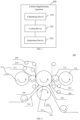
- Fig. 1 is a schematic block diagram of a lithium supplementing apparatus according to the embodiments of the present application.
- the lithium supplementing apparatus 100 includes a plurality of calendering devices 110, a coating device 120, and a segmenting device 130; in which the plurality of calendering devices 110 are used for respectively transferring lithium on the plurality of lithium strips 200 to a plurality of first regions 1211 distributed in a first direction X on the coating device 120, the first direction X being a width direction of a first electrode plate 210 to be subjected to lithium supplementing;
- the coating device 120 is used for coating the lithium in the plurality of first regions 1211 onto a plurality of second regions 1221 corresponding to the plurality of first regions 1211 on the first electrode plate 210 respectively;
- the segmenting device 130 is used for segmenting the first electrode plate 210 according to the plurality of second regions 1221 so as to form a plurality of segmented second electrode plates 220.
- the plurality of first regions 1211 are a plurality of regions distributed in the first direction X on the coating device 120
- the plurality of second regions 1221 are a plurality of regions distributed in the first direction X on the first electrode plate 210
- lithium on each of the first regions 1211 on the coating device 120 is coated onto the corresponding second regions 1221 on the first electrode plate 210.
- the first direction X is a width direction of the first electrode plate 210, i.e. the width direction of the first electrode plate 210.
- the first electrode plate 210 is a electrode plate with a large width. After lithium is coated onto the plurality of second regions 1221 on the first electrode plate 210 at the same time, the plurality of second electrode plates 220 corresponding to the plurality of second regions 1221 are formed by means of segmentation, where each of the second electrode plates 220 includes a corresponding second region 1221 after being subjected to lithium supplementing.
- the lithium on the lithium strips 200 is simultaneously transferred to the plurality of first regions 1211 distributed in the width direction X of the electrode plate on the coating device 120; by the coating device 120, the lithium in the plurality of first region 1211 is transferred to the corresponding plurality of second region 1221 on the first electrode plate 210; and then, the segmenting device 130 segments the first electrode plate 210 on the basis of the plurality of second regions 1221, so as to form a plurality of segmented second electrode plates 220.
- the lithium supplementing efficiency is greatly improved.
- a calendering device 110 includes calendering rollers 111
- a coating device 120 includes a fast roller 121
- lithium strips 200 pass through between the fast roller 121 and the calendering rollers 111, so that lithium on the lithium strips 200 is transferred to first regions 1211 on the fast roller 121 corresponding to the lithium strips 200.
- the lithium on the lithium strips 200 is transferred to the coating device 120 by using roller systems, in which the calendering device 110 includes calendering rollers 111, and the coating device 120 includes a fast roller 121; by means of relative movement between the calendering rollers 111 and the fast roller 121, the lithium strips 200 passes through between the fast roller 121 and the calendering rollers 111, so that lithium on each lithium strip 200 is transferred to the first regions 1211 on the fast roller 121 corresponding to the lithium strips 200, which is easy to implement and has high reliability.
- roller systems in which the calendering device 110 includes calendering rollers 111, and the coating device 120 includes a fast roller 121; by means of relative movement between the calendering rollers 111 and the fast roller 121, the lithium strips 200 passes through between the fast roller 121 and the calendering rollers 111, so that lithium on each lithium strip 200 is transferred to the first regions 1211 on the fast roller 121 corresponding to the lithium strips 200, which is easy to implement and has
- the coating device 120 further includes a laminating roller 122, and the first electrode plate 210 passes through between the fast roller 121 and the laminating roller 122, so as to coat lithium in the first regions 1211 on the fast roller 121 onto the second regions 1221 on the first electrode plate 210 corresponding to the first regions 1211.
- the lithium on the coating device 120 is transferred to the first electrode plate 210 by using roller systems
- the coating device 120 further includes a laminating roller 122 provided opposite to the fast roller 121, and by means of the relative movement between the laminating roller 122 and the fast roller 121, the first electrode plate 210 passes through between the fast roller 121 and the laminating roller 122, so that the lithium in the first regions 1211 on the fast roller 121 is coated onto the second regions 1221 on the first electrode plate 210 corresponding to the first regions 1211, which is easy to implement and has high reliability.
- Fig. 2 is a schematic structural diagram of a possible implementation of the lithium supplementing apparatus 100 shown in Fig. 1 .
- the calendering device 110 includes calendering rollers 111
- the coating device 120 includes a fast roller 121 and a laminating roller 122.
- the plurality of calendering rolls 111 surround the fast roller 121 and are staggered in the first direction X, that is, the roller surfaces of the calendering rollers 111 do not overlap in the first direction X.
- the lithium strips 200 pass through between the fast roller 121 and the calendering rollers 111, the lithium on the lithium strips 200 is transferred to the first regions 1211 on the fast roller 121 corresponding to the lithium strips 200.
- the lithium in the first regions 1211 on the fast roller 121 is transferred to the second regions 1221 on the first electrode plate 210 corresponding to the first regions 1211.
- the size of the calendering rollers 111 is smaller than the size of the fast roller 121, for example, as shown in Fig. 2 , the diameter of the calendering rollers 111 is smaller than the diameter of the fast roller 121, and the size of the calendering rollers 11 in the first direction X is also smaller than the size of the fast roller 121.
- the side of the calendering rollers 111 facing the fast roller 121 may bear a relatively large pressure, which tends to cause loss to the calendering rollers 111, and affects the service life thereof.
- the calendering device 110 can further include back rollers 112, the calendering rollers 111 are located between the back rollers 112 and the fast roller 121, and the back rollers 112 are used to provide a supporting force to the calendering rollers 111 toward the fast roller 121.
- the back rollers 112 By adding the back rollers 112, a supporting force towards the fast roller 121 is provided to the calendering rollers 111, and the pressure applied to the calendering rollers 111 by the fast roller 121 can be balanced, thereby protecting the calendering rollers 111.
- Fig. 2 shows a plurality of calendering devices 110.
- Fig. 3 shows a case where there is only one calendering device 110, and "one-into-one" can be achieved, i.e. only one second electrode plate 220 is sent out after a first electrode plate 210 is sent into the lithium supplementing apparatus 100.
- Fig. 4 shows a case where two calendering devices 110 are provided, i.e.
- Figs. 5 and 6 show a case where three calendering devices 110 are provided, i.e. "one-into-three” can be achieved, that is, three second electrode plates 220 are sent out after a first electrode plate 210 is sent into the lithium supplementing apparatus 100.
- Fig. 7 shows a case where four calendering devices 110 are provided, i.e. "one-into-four” can be achieved, that is, four second electrode plates 220 are sent out after a first electrode plate 210 is sent into the lithium supplementing apparatus 100.
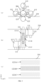
- Fig. 3 is a schematic diagram of the relative positions of the calendering devices 110 and the coating device 120 in the lithium supplementing apparatus 100 shown in Fig. 2 , in which (a) in Fig. 3 is a side view of the calendering devices 11 and the coating device 120, (b) is a top view thereof, and (c) is a schematic diagram of the surface of the first electrode plate 210 facing towards the calendering devices 110.
- Each calendering device 110 includes calendering rollers 111 and back rollers 112, and the coating device 120 includes a fast roller 121 and a laminating roller 122. It can be determined from Fig.
- the fast roller 121 and the calendering rollers 111 are oppositely provided in a Y direction, the Y direction is perpendicular to the first direction X, and the first direction X is the width direction of the first electrode plate 210.
- the lithium strips 200 pass through between the fast roller 121 and the calendering rollers 111, the lithium on the lithium strips 200 is transferred to the first regions 1211 of the fast roller 121.
- the first electrode plate 210 passes through between the fast roller 121 and the laminating roller 122, the lithium in the first regions 1211 of the fast roller 121 is transferred to the second regions 1221 on the first electrode plate 210 corresponding to the first region 1211.
- FIG. 4 Compared with Fig. 3 , two calendering devices 110 are provided in Fig. 4 .
- Fig. 4 (a) is a side view of the calendering devices 110 and the coating device 120, (b) is a top view thereof, and (c) is a schematic diagram of the surface of the first electrode plate 210 facing the calendering devices 110. It can be determined from Fig. 4 that two calendering rollers 111 are provided on both sides of the fast roller 121 in the Y direction, and the two calendering rollers 111 are staggered in the first direction X.
- One lithium strip 200 passes through between the fast roller 121 and one calendering roller 111, and the other lithium strip 200 passes through between the fast roller 121 and the other calendering roller 111.
- lithium on the two lithium strips 200 can be simultaneously transferred to two first regions 1211 arranged in the first direction X of the fast roller 121, including a first region 1211A and a first region 1211B.
- the first region 1211A and the first region 1211B are filled with different line patterns to distinguish them.
- the lithium in the first region 1211A of the fast roller 121 is transferred to the second region 1221A on the first electrode plate 210 corresponding to the first region 1211A, and the lithium in the first region 1211B of the fast roller 121 is transferred to the second region 1221B on the first electrode plate 210 corresponding to the first region 1211B.
- FIG. 5 Compared with Fig. 4 , three calendering devices 110 are provided in Fig. 5 .
- Fig. 5 (a) is a side view of the calendering devices 110 and the coating device 120, (b) is a top view thereof, and (c) is a schematic diagram of the surface of the first electrode plate 210 facing the calendering devices 110.
- two calendering rollers 111 are arranged on both sides of the fast roller 121 in the Y direction, and another calendering roller 111 is arranged on a side of the fast roller 121 in the first direction X; and the three calendering rolls 111 are staggered in the first direction X.
- the lithium strips 200 passes through between the fast roller 121 and each of the calendering rollers 111, so that the lithium on the lithium strips 200 is simultaneously transferred to the three first regions 1211 of the fast roller 121 arranged in the first direction X, including a first region 1211A, a first region 1211B and a first region 1211C.
- the first region 1211A, the first region 1211B and the first region 1211C are filled with different line patterns so as to distinguish them.
- the lithium in the first region 1211A of the fast roller 121 is transferred to the second region 1221A of the first electrode plate 210 corresponding to the first region 1211A
- the lithium in the first region 1211B of the fast roller 121 is transferred to the second region 1221B of the first electrode plate 210 corresponding to the first region 1211B
- the lithium in the first region 1211C of the fast roller 121 is transferred to the second region 1221C of the first electrode plate 210 corresponding to the first region 1211C.
- FIG. 6 Compared with Fig. 4 , three calendering devices 110 are provided in Fig. 6 .
- the difference between Figs. 6 and 5 is that the relative positions of the three calendering rollers 111 are different.
- (a) is a side view of the calendering devices 110 and the coating device 120
- (b) is a top view thereof
- (c) is a schematic diagram of the surface of the first electrode plate 210 facing the calendering devices 110. It can be determined from Fig.
- the lithium strips 200 pass through between the fast roller 121 and each of the calendering rollers 111, so that the lithium on the lithium strips 200 is simultaneously transferred to the three first regions 1211 of the fast roller 121 arranged in the first direction X, including a first region 1211A, a first region 1211B and a first region 1211C.
- the first region 1211A, the first region 1211B and the first region 1211C are filled with different line patterns so as to distinguish them. Then, when the first electrode plate 210 passes through between the fast roller 121 and the laminating roller 122 from left to right, the lithium in the first region 1211A of the fast roller 121 is transferred to the second region 1221A corresponding to the first region 1211A on the first electrode plate 210, the lithium in the first region 1211B of the fast roller 121 is transferred to the second region 1221B corresponding to the first region 1211B on the first electrode plate 210, and the lithium in the first region 1211C of the fast roller 121 is transferred to the second region 1221C corresponding to the first region 1211C on the first electrode plate 210.
- Fig. 7 Compared with Figs. 5 and 6 , four calendering devices 110 are provided in Fig. 7 .
- Fig. 7 (a) is a side view of the calendering devices 110 and the coating device 120, (b) is a top view thereof, and (c) is a schematic diagram of the surface of the first electrode plate 210 facing the calendering devices 110. It can be determined from Fig. 7 that, at two sides of the fast roller 121 in the Y direction, one side is provided with two calendering rollers 111, and the other side is provided with two calendering rollers 111; and the four calendering rollers 111 are staggered in the first direction X.
- the lithium strips 200 pass through between the fast roller 121 and each of the calendering rollers 111, so that the lithium on the lithium strips 200 is simultaneously transferred to the three first regions 1211 of the fast roller 121 arranged in the first direction X, including the first region 1211A, the first region 1211B and the first region 1211C.
- the first region 1211A, the first region 1211B, the first region 1211C and the first region 1211D are filled with different line patterns so as to distinguish them.
- the lithium in the first region 1211A of the fast roller 121 is transferred to the second region 1221A corresponding to the first region 1211A on the first electrode plate 210
- the lithium in the first region 1211B of the fast roller 121 is transferred to the second region 1221B corresponding to the first region 1211B on the first electrode plate 210
- the lithium in the first region 1211C of the fast roller 121 is transferred to the second region 1221C corresponding to the first region 1211C on the first electrode plate 210
- the lithium in the first region 1211D of the fast roller 121 is transferred to the second region 1221D corresponding to the first region 1211D on the first electrode plate 210.
- Figs. 3-7 are merely examples, and the relative position between the plurality of calendering rollers 111 and the fast roller 121 may also have other implementations.
- the number of calendering rollers 111 may also be larger.
- a protective belt 210 is provided between the lithium strips 200 and the calendering rollers 111, the protective belt 210 and the lithium strips 200 pass through between the fast roller 121 and the calendering rollers 111 at the same time, and the protective belt 210 is used for isolating the lithium strips 200 from the calendering rollers 111.
- the protective belt 210 can protect the lithium strips 200, so as to prevent the lithium strips 200 from being damaged when passing through between the fast roller 121 and the calendering rollers 111.
- the material of the protective belt 210 is, for example, polyethylene terephthalate (PET) and the like, which is easy to acquire and has a low cost.
- the calendering device 110 further includes a scraper 140, the scraper 140 being used for controlling the width of the lithium in the first direction X in the first region 1211 on the fast roller 111.
- the scraper 140 By means of the scraper 140, the width of the lithium in the first region 1211 of the fast roller 11 can be precisely controlled to match the width of the corresponding second electrode plate 220.
- the widths of lithium of the first region 1211A, the first region 1211B, the first region 1211C, and the first region 1211D in the first direction X may be controlled by the scraper 140.
- the scraper 140 corresponding to the first region 1211A can scrape off lithium outside the width W in the rotation process of the fast roller 121, and keep the lithium within the width W, so that the width of lithium transferred to the second region 1221A corresponding to the first region 1211A on the first electrode plate 210 is W, so as to match the width of the second electrode plate 220 corresponding to the second region 1221A.
- the second regions 1221 of the plurality of second regions 1221 have different widths in the first direction X. That is, the plurality of second regions 1221 may have the same width in the first direction X, or may have different widths in part or all of the first direction X.
- the widths in the first direction X of the first region 1211A, the first region 1211B, the first region 1211C, and the first region 1211D may be the same or different.
- the widths of the second regions 1221A, the second regions 1221B, the second regions 1221C, and the second regions 1221D on the first electrode plate 210 are also different, and after segmentation is performed by the segmenting device 130, the plurality of second electrode plates 220 with different widths can be formed.
- a plurality of second electrode plates 220 with different widths after being subjected to lithium supplementing may be simultaneously formed, and the lithium supplementing apparatus is more applicable.
- the lithium supplementing apparatus 100 includes a first sub-apparatus 101 and a second sub-apparatus 102, each of the first sub-apparatus 101 and the second sub-apparatus 02 includes the plurality of calendering devices 110 and the coating device 120, the first sub-apparatus 101 is used for coating lithium on the plurality of second regions 1221 on the first surface 210A of the first electrode plate 210, and the second sub-apparatus is used for coating lithium on the plurality of second regions 1221 on the second surface 210B of the first electrode plate 210.
- the lithium supplementing apparatus 100 includes two sets of sub-apparatuses, that is, a first sub-apparatus 101 and a second sub-apparatus 102; the first sub-apparatus 101 is used for performing lithium supplementing on a first surface 210A of a first electrode plate 210, and the second sub-apparatus 102 is used for performing lithium supplementing on a second surface 210B of the first electrode plate 210.
- the process of performing, by the second set of sub-apparatus 102, lithium supplementing on the second surface 210B of the first electrode plate 210 is similar to the described process of performing, by the first sub-apparatus 101, lithium supplementing on the first surface 210A of the first electrode plate 210.
- lithium supplementing is performed on the two surfaces of the first electrode plate 210 successively, thereby enhancing the lithium supplementing effect of the second electrode plate 220.
- segmentation is performed by means of the segmenting device 130 to form a plurality of second electrode plates 220.
- the first electrode plate 210 needs to be segmented by the segmenting device 130 on the basis of the plurality of second regions 1221, so as to form a plurality of segmented second electrode plates 220.
- the segmenting device 130 includes, for example, a mechanical cutter or a laser cutter, and segments the first electrode plate 210 by means of the mechanical cutter or the laser cutter, which is easy to operate and has high reliability.
- a circular cutter is taken as an example, and the circular cutter is used to segment the first electrode plate 210 on the basis of the plurality of second regions 1221, so as to form the plurality of second electrode plates 220 corresponding to the plurality of second regions.
- each segmented second electrode plate 220 may also be performed on each segmented second electrode plate 220 to form a part such as a tab, where the tab is formed in a region of the second electrode plate 220 in which lithium is not coated. Thereafter, the electrode assembly is formed by, for example, winding or laminating.
- the lithium supplementing apparatus 100 further includes an unwinding device 150 used for releasing the first electrode plate 210.
- the unwinding device 150 may be, for example, an unwinding roller 150.
- the lithium supplementing apparatus 100 further includes a plurality of winding devices 160, used for winding the plurality of second electrode plates 220 after being subjected to lithium supplementing.
- the winding devices 160 may be, for example, winding rollers 160.
- unwinding device 150 and the plurality of winding devices 160 By means of the unwinding device 150 and the plurality of winding devices 160, unwinding of the first electrode plate 210 and unwinding of the plurality of second electrode plates 220 are completed respectively, which is easy to operate and has high reliability.
- Fig. 9 shows a lithium supplementing method 300 according to the embodiments of the present application.
- the lithium supplementing method 300 may be executed by the lithium supplementing apparatus 100.
- the method 100 includes some or all of the following steps:
- the calendering device 110 includes calendering rollers 111
- the coating device 120 includes a fast roller 121
- the transferring lithium on the plurality of lithium strips 200 to a plurality of first regions 1211 distributed in a first direction X on the coating device 120 respectively includes: the lithium strips 200 passing through between the fast roller and the calendering rollers 111, so that the lithium on the lithium strips 200 is transferred to the first regions 1211 corresponding to the lithium strips 200 on the fast roller 121.
- a protective belt 210 is provided between the lithium strips 200 and the calendering rollers 111, and the lithium strips 200 passing through between the fast roller 121 and the calendering rollers 111 includes: the protective belt 210 and the lithium strips 200 passing through between the fast roller 121 and the calendering rollers 111 at the same time, the protective belt 210 being used for isolating the lithium strips 200 from the calendering rollers 111.
- the material of the protective belt 210 is PET.
- the calendering device 110 further includes a scraper 140
- the method further includes: controlling, by the scraper 140, the width of the first regions 1211 on the fast roller in the first direction X.
- the coating device 120 further includes a laminating roller 122, and the coating the lithium of the plurality of first regions 1211 onto the plurality of second regions 1221 of the first electrode plate 210 corresponding to the plurality of first regions 1211 respectively includes: the first electrode plate 210 passing through between the fast roller and the laminating roller 122, so as to coat the lithium of the first regions 1211 on the fast roller 121 onto the second regions 1221 of the first electrode plate 210 corresponding to the first regions 1211.
- At least some of the second regions 1221 of the plurality of second regions 1221 have different widths in the first direction X.
- the method 300 further includes: by means of a plurality of winding devices 160, respectively performing winding on the plurality of second electrode plates 220 after being subjected to lithium supplementing.
- the units described as separate parts may or may not be physically separate, and parts displayed as units may or may not be physical units, i.e. may be located in one position, or may be distributed on a plurality of network units. Some or all of the units may be selected according to actual requirements to achieve the purposes of the solutions of the embodiments.
Landscapes
- Engineering & Computer Science (AREA)
- Manufacturing & Machinery (AREA)
- Chemical & Material Sciences (AREA)
- Chemical Kinetics & Catalysis (AREA)
- Electrochemistry (AREA)
- General Chemical & Material Sciences (AREA)
- Battery Electrode And Active Subsutance (AREA)
Applications Claiming Priority (1)
| Application Number | Priority Date | Filing Date | Title |
|---|---|---|---|
| PCT/CN2022/106832 WO2024016226A1 (zh) | 2022-07-20 | 2022-07-20 | 补锂装置和补锂方法 |
Publications (2)
| Publication Number | Publication Date |
|---|---|
| EP4485553A1 true EP4485553A1 (de) | 2025-01-01 |
| EP4485553A4 EP4485553A4 (de) | 2025-06-11 |
Family
ID=89616628
Family Applications (1)
| Application Number | Title | Priority Date | Filing Date |
|---|---|---|---|
| EP22951504.4A Pending EP4485553A4 (de) | 2022-07-20 | 2022-07-20 | Lithiumergänzungsvorrichtung und lithiumergänzungsverfahren |
Country Status (4)
| Country | Link |
|---|---|
| US (1) | US20250087659A1 (de) |
| EP (1) | EP4485553A4 (de) |
| CN (1) | CN118974958A (de) |
| WO (1) | WO2024016226A1 (de) |
Family Cites Families (7)
| Publication number | Priority date | Publication date | Assignee | Title |
|---|---|---|---|---|
| JP2010212143A (ja) * | 2009-03-11 | 2010-09-24 | Nissan Motor Co Ltd | 電極製造方法および電極製造装置 |
| CN105845896B (zh) * | 2016-05-16 | 2018-07-13 | 宁德时代新能源科技股份有限公司 | 分体压延一次性覆膜补锂装置 |
| CN105845897B (zh) * | 2016-05-16 | 2018-07-13 | 宁德时代新能源科技股份有限公司 | 分体压延分体复合补锂装置 |
| CN207558931U (zh) * | 2017-12-21 | 2018-06-29 | 宁德时代新能源科技股份有限公司 | 补锂装置 |
| CN118645590A (zh) * | 2019-11-21 | 2024-09-13 | 宁德时代新能源科技股份有限公司 | 极片补锂装置和极片补锂方法 |
| CN111519135A (zh) * | 2020-03-30 | 2020-08-11 | 维达力实业(深圳)有限公司 | 遮蔽装置及补锂设备 |
| CN113889600B (zh) * | 2021-09-30 | 2023-04-14 | 蜂巢能源科技有限公司 | 一种预锂工艺、预锂装置及叠片工艺、叠片装置 |
-
2022
- 2022-07-20 WO PCT/CN2022/106832 patent/WO2024016226A1/zh not_active Ceased
- 2022-07-20 EP EP22951504.4A patent/EP4485553A4/de active Pending
- 2022-07-20 CN CN202280093961.4A patent/CN118974958A/zh active Pending
-
2024
- 2024-11-26 US US18/959,672 patent/US20250087659A1/en active Pending
Also Published As
| Publication number | Publication date |
|---|---|
| CN118974958A (zh) | 2024-11-15 |
| US20250087659A1 (en) | 2025-03-13 |
| WO2024016226A1 (zh) | 2024-01-25 |
| EP4485553A4 (de) | 2025-06-11 |
Similar Documents
| Publication | Publication Date | Title |
|---|---|---|
| US20230170592A1 (en) | Electrode assembly, battery cell, battery, and electric apparatus | |
| US12412933B2 (en) | Electrode assembly, battery cell, battery, manufacturing method and device for electrode assembly | |
| US20230163419A1 (en) | Battery cell, battery, power consuming apparatus, and method and apparatus for manufacturing battery cell | |
| US20230268601A1 (en) | Battery, power consumption device, and method and device for producing battery | |
| EP4068490A1 (de) | Batteriezelle, batterie, elektrische vorrichtung, herstellungsverfahren und vorrichtung für eine batteriezelle | |
| US12506155B2 (en) | Electrode assembly, battery cell, battery, and method and device for manufacturing electrode assembly | |
| US20230246199A1 (en) | Battery plate, electrode assembly, battery cell, battery and power consuming device | |
| US20240274777A1 (en) | Electrode sheet forming method, manufacturing method for wound electrode assembly, and manufacturing method for laminated electrode assembly | |
| US20240313303A1 (en) | Battery cell, battery, and electrical device | |
| US20250192398A1 (en) | Electrode assembly, battery cell, battery, and electrical device | |
| US20250149743A1 (en) | Battery cell, battery and electrical apparatus | |
| WO2023029795A1 (zh) | 电极组件、电池单体、电池及用电设备 | |
| US20240421435A1 (en) | Battery cell, battery module, battery, and electric apparatus | |
| CN115863787A (zh) | 电池单体、动力电池及用电设备 | |
| KR102958139B1 (ko) | 전극 조립체 및 그 제조 방법, 배터리 셀, 배터리 및 전기기기 | |
| US12341161B2 (en) | Electrode assembly, battery cell, battery and electric apparatus | |
| US20250087659A1 (en) | Lithium supplementing apparatus and lithium supplementing method | |
| EP4328991A1 (de) | Elektrodenanordnung, batteriezelle, batterie und elektrische vorrichtung | |
| US20240313359A1 (en) | Separator of electrode assembly, and method and device for preparing separator of electrode assembly | |
| US20240339626A1 (en) | Electrode assembly, battery cell, battery, and electric device | |
| EP4421971A1 (de) | Batterieelektrodenplatte, elektrodenanordnung, batteriezelle, batterie und elektrische vorrichtung | |
| EP4560819A1 (de) | Elektrodenanordnung und herstellungsverfahren dafür, sekundärbatterie und elektrische vorrichtung | |
| EP4276963A1 (de) | Elektrodenanordnung, zelle, batterie und leistungsvorrichtung | |
| US20250379262A1 (en) | Battery cell, battery, and power consuming apparatus | |
| US20240258585A1 (en) | Battery cell, battery and power consumption apparatus |
Legal Events
| Date | Code | Title | Description |
|---|---|---|---|
| STAA | Information on the status of an ep patent application or granted ep patent |
Free format text: STATUS: THE INTERNATIONAL PUBLICATION HAS BEEN MADE |
|
| PUAI | Public reference made under article 153(3) epc to a published international application that has entered the european phase |
Free format text: ORIGINAL CODE: 0009012 |
|
| STAA | Information on the status of an ep patent application or granted ep patent |
Free format text: STATUS: REQUEST FOR EXAMINATION WAS MADE |
|
| 17P | Request for examination filed |
Effective date: 20240924 |
|
| AK | Designated contracting states |
Kind code of ref document: A1 Designated state(s): AL AT BE BG CH CY CZ DE DK EE ES FI FR GB GR HR HU IE IS IT LI LT LU LV MC MK MT NL NO PL PT RO RS SE SI SK SM TR |
|
| A4 | Supplementary search report drawn up and despatched |
Effective date: 20250513 |
|
| RIC1 | Information provided on ipc code assigned before grant |
Ipc: H01M 10/0525 20100101ALI20250507BHEP Ipc: H01M 10/058 20100101ALI20250507BHEP Ipc: H01M 4/04 20060101AFI20250507BHEP |
|
| DAV | Request for validation of the european patent (deleted) | ||
| DAX | Request for extension of the european patent (deleted) |