EP4485576A1 - Sekundärbatterie, batteriemodul, batteriepack und elektrische vorrichtung - Google Patents
Sekundärbatterie, batteriemodul, batteriepack und elektrische vorrichtung Download PDFInfo
- Publication number
- EP4485576A1 EP4485576A1 EP22934332.2A EP22934332A EP4485576A1 EP 4485576 A1 EP4485576 A1 EP 4485576A1 EP 22934332 A EP22934332 A EP 22934332A EP 4485576 A1 EP4485576 A1 EP 4485576A1
- Authority
- EP
- European Patent Office
- Prior art keywords
- group
- optionally
- secondary battery
- positive electrode
- coating layer
- Prior art date
- Legal status (The legal status is an assumption and is not a legal conclusion. Google has not performed a legal analysis and makes no representation as to the accuracy of the status listed.)
- Pending
Links
Images


Classifications
-
- H—ELECTRICITY
- H01—ELECTRIC ELEMENTS
- H01M—PROCESSES OR MEANS, e.g. BATTERIES, FOR THE DIRECT CONVERSION OF CHEMICAL ENERGY INTO ELECTRICAL ENERGY
- H01M4/00—Electrodes
- H01M4/02—Electrodes composed of, or comprising, active material
- H01M4/36—Selection of substances as active materials, active masses, active liquids
- H01M4/362—Composites
- H01M4/366—Composites as layered products
-
- H—ELECTRICITY
- H01—ELECTRIC ELEMENTS
- H01M—PROCESSES OR MEANS, e.g. BATTERIES, FOR THE DIRECT CONVERSION OF CHEMICAL ENERGY INTO ELECTRICAL ENERGY
- H01M10/00—Secondary cells; Manufacture thereof
- H01M10/05—Accumulators with non-aqueous electrolyte
- H01M10/052—Li-accumulators
- H01M10/0525—Rocking-chair batteries, i.e. batteries with lithium insertion or intercalation in both electrodes; Lithium-ion batteries
-
- H—ELECTRICITY
- H01—ELECTRIC ELEMENTS
- H01M—PROCESSES OR MEANS, e.g. BATTERIES, FOR THE DIRECT CONVERSION OF CHEMICAL ENERGY INTO ELECTRICAL ENERGY
- H01M10/00—Secondary cells; Manufacture thereof
- H01M10/05—Accumulators with non-aqueous electrolyte
- H01M10/056—Accumulators with non-aqueous electrolyte characterised by the materials used as electrolytes, e.g. mixed inorganic/organic electrolytes
- H01M10/0564—Accumulators with non-aqueous electrolyte characterised by the materials used as electrolytes, e.g. mixed inorganic/organic electrolytes the electrolyte being constituted of organic materials only
- H01M10/0566—Liquid materials
- H01M10/0567—Liquid materials characterised by the additives
-
- H—ELECTRICITY
- H01—ELECTRIC ELEMENTS
- H01M—PROCESSES OR MEANS, e.g. BATTERIES, FOR THE DIRECT CONVERSION OF CHEMICAL ENERGY INTO ELECTRICAL ENERGY
- H01M4/00—Electrodes
- H01M4/02—Electrodes composed of, or comprising, active material
- H01M4/13—Electrodes for accumulators with non-aqueous electrolyte, e.g. for lithium-accumulators; Processes of manufacture thereof
- H01M4/136—Electrodes based on inorganic compounds other than oxides or hydroxides, e.g. sulfides, selenides, tellurides, halogenides or LiCoFy
-
- H—ELECTRICITY
- H01—ELECTRIC ELEMENTS
- H01M—PROCESSES OR MEANS, e.g. BATTERIES, FOR THE DIRECT CONVERSION OF CHEMICAL ENERGY INTO ELECTRICAL ENERGY
- H01M4/00—Electrodes
- H01M4/02—Electrodes composed of, or comprising, active material
- H01M4/36—Selection of substances as active materials, active masses, active liquids
- H01M4/58—Selection of substances as active materials, active masses, active liquids of inorganic compounds other than oxides or hydroxides, e.g. sulfides, selenides, tellurides, halogenides or LiCoFy; of polyanionic structures, e.g. phosphates, silicates or borates
-
- H—ELECTRICITY
- H01—ELECTRIC ELEMENTS
- H01M—PROCESSES OR MEANS, e.g. BATTERIES, FOR THE DIRECT CONVERSION OF CHEMICAL ENERGY INTO ELECTRICAL ENERGY
- H01M4/00—Electrodes
- H01M4/02—Electrodes composed of, or comprising, active material
- H01M4/36—Selection of substances as active materials, active masses, active liquids
- H01M4/58—Selection of substances as active materials, active masses, active liquids of inorganic compounds other than oxides or hydroxides, e.g. sulfides, selenides, tellurides, halogenides or LiCoFy; of polyanionic structures, e.g. phosphates, silicates or borates
- H01M4/5825—Oxygenated metallic salts or polyanionic structures, e.g. borates, phosphates, silicates, olivines
-
- H—ELECTRICITY
- H01—ELECTRIC ELEMENTS
- H01M—PROCESSES OR MEANS, e.g. BATTERIES, FOR THE DIRECT CONVERSION OF CHEMICAL ENERGY INTO ELECTRICAL ENERGY
- H01M4/00—Electrodes
- H01M4/02—Electrodes composed of, or comprising, active material
- H01M4/62—Selection of inactive substances as ingredients for active masses, e.g. binders, fillers
- H01M4/624—Electric conductive fillers
- H01M4/625—Carbon or graphite
-
- C—CHEMISTRY; METALLURGY
- C01—INORGANIC CHEMISTRY
- C01B—NON-METALLIC ELEMENTS; COMPOUNDS THEREOF; METALLOIDS OR COMPOUNDS THEREOF NOT COVERED BY SUBCLASS C01C
- C01B25/00—Phosphorus; Compounds thereof
- C01B25/16—Oxyacids of phosphorus; Salts thereof
- C01B25/26—Phosphates
- C01B25/45—Phosphates containing plural metal, or metal and ammonium
-
- H—ELECTRICITY
- H01—ELECTRIC ELEMENTS
- H01M—PROCESSES OR MEANS, e.g. BATTERIES, FOR THE DIRECT CONVERSION OF CHEMICAL ENERGY INTO ELECTRICAL ENERGY
- H01M4/00—Electrodes
- H01M4/02—Electrodes composed of, or comprising, active material
- H01M2004/021—Physical characteristics, e.g. porosity, surface area
-
- H—ELECTRICITY
- H01—ELECTRIC ELEMENTS
- H01M—PROCESSES OR MEANS, e.g. BATTERIES, FOR THE DIRECT CONVERSION OF CHEMICAL ENERGY INTO ELECTRICAL ENERGY
- H01M4/00—Electrodes
- H01M4/02—Electrodes composed of, or comprising, active material
- H01M2004/026—Electrodes composed of, or comprising, active material characterised by the polarity
- H01M2004/028—Positive electrodes
-
- H—ELECTRICITY
- H01—ELECTRIC ELEMENTS
- H01M—PROCESSES OR MEANS, e.g. BATTERIES, FOR THE DIRECT CONVERSION OF CHEMICAL ENERGY INTO ELECTRICAL ENERGY
- H01M2300/00—Electrolytes
- H01M2300/0017—Non-aqueous electrolytes
- H01M2300/0025—Organic electrolyte
-
- Y—GENERAL TAGGING OF NEW TECHNOLOGICAL DEVELOPMENTS; GENERAL TAGGING OF CROSS-SECTIONAL TECHNOLOGIES SPANNING OVER SEVERAL SECTIONS OF THE IPC; TECHNICAL SUBJECTS COVERED BY FORMER USPC CROSS-REFERENCE ART COLLECTIONS [XRACs] AND DIGESTS
- Y02—TECHNOLOGIES OR APPLICATIONS FOR MITIGATION OR ADAPTATION AGAINST CLIMATE CHANGE
- Y02E—REDUCTION OF GREENHOUSE GAS [GHG] EMISSIONS, RELATED TO ENERGY GENERATION, TRANSMISSION OR DISTRIBUTION
- Y02E60/00—Enabling technologies; Technologies with a potential or indirect contribution to GHG emissions mitigation
- Y02E60/10—Energy storage using batteries
Definitions
- This application relates to the field of lithium battery technologies, and in particular, to a secondary battery, a battery module, a battery pack, and an electric apparatus.
- lithium-ion batteries have been widely used in energy storage power supply systems such as hydroelectric, thermal, wind, and solar power plants, and many other fields including electric tools, electric bicycles, electric motorcycles, electric vehicles, military equipment, and aerospace.
- energy storage power supply systems such as hydroelectric, thermal, wind, and solar power plants
- electric tools such as electric bicycles, electric motorcycles, electric vehicles, military equipment, and aerospace.
- higher requirements are imposed on their energy density, cycling performance, safety performance, and the like.
- lithium manganese phosphate positive electrode active materials Compared with other positive electrode active materials, lithium manganese phosphate positive electrode active materials have higher safety and better cycle life. However, lithium manganese phosphate has a disadvantage of poor rate performance. Currently, this problem is typically addressed through methods such as coating or doping. It would be still desired to further improve the rate performance, cycling performance, high-temperature stability, and the like of lithium manganese phosphate positive electrode active materials.
- An objective of this application is to provide a secondary battery, a battery module, a battery pack, and an electric apparatus so as to solve the problem of poor rate performance and cycling performance of lithium manganese phosphate secondary batteries.
- a first aspect of this application provides a secondary battery including a positive electrode plate and a non-aqueous electrolyte, where a positive electrode active material includes a core and a shell enveloping the core, the core including Li 1+x Mn 1-y A y P 1-z R z O 4 , where x is in the range of -0.100 to 0.100, y is in the range of 0.001 to 0.500, z is in the range of 0.001 to 0.100, A is one or more selected from a group consisting of Zn, Al, Na, K, Mg, Mo, W, Ti, V, Zr, Fe, Ni, Co, Ga, Sn, Sb, Nb, and Ge, optionally one or more selected from a group consisting of Fe, Ti, V, Ni, Co, and Mg, and R is one or more selected from a group consisting of B, Si, N, and S; and the shell including a first coating layer enveloping the core and a second coating
- the non-aqueous electrolyte includes a first additive, the first additive including one or more from a group consisting of compounds shown in formula 1 and compounds shown in formula 2,
- the foregoing limitation on the value range of y is not only a limitation on the stoichiometric number of each element as A but also a limitation on the sum of the stoichiometric numbers of all elements as A.
- the stoichiometric numbers y1, y2, ..., yn of all of A1, A2, ..., An must fall within the value range defined by this application for y, and the sum of y1, y2, ..., yn must also fall within the value range.
- R is two or more elements
- the limitation on the value range of the stoichiometric number of R in this application also has the foregoing meaning.
- the lithium manganese phosphate positive electrode active material in this application is a core-shell structure with two coating layers, where the core includes Li 1+x Mn 1-y A y P 1-z R z O 4 .
- Element A doping at the manganese site of lithium manganese phosphate in the core helps to decrease the lattice change rate of lithium manganese phosphate during lithium deintercalation and intercalation, improve the structural stability of the lithium manganese phosphate positive electrode material, and greatly reduce the dissolution of manganese and reduce particle surface oxygen activity.
- Element R doping at the phosphorus site helps to change difficulty in varying the Mn-O bond length, thereby reducing the migration barrier of lithium ions, promoting the migration of lithium ions, and improving the rate performance of the secondary battery.
- the first coating layer of the positive electrode active material in this application includes a pyrophosphate and a phosphate.
- the high migration barrier (> 1 eV) of transition metals in the pyrophosphate can effectively inhibit the dissolution of transition metals.
- the crystalline phosphate has excellent ability to conduct lithium ions, and may decrease the amount of impurity lithium on the surface.
- the second coating layer can effectively improve the electrical conductivity and desolvation ability of LiMnPO 4 .
- the "barrier" function of the second coating layer can further hinder the migration of manganese ions into the electrolyte and reduce the corrosion of the active material by the electrolyte.
- lithium manganese phosphate in this application, it is possible to effectively inhibit the dissolution of manganese ions during lithium deintercalation and intercalation, and promote the migration of lithium ions, thereby improving the rate performance of the cell and improving the cycling performance and high-temperature performance of the secondary battery.
- a first additive is introduced into the non-aqueous electrolyte to form a polymer layer on the surface of the coating layer during charging of the lithium-ion battery. This prevents the dissolution of the coating layers, reduces the dissolution of manganese ions, lowers the catalytic activity of the coated carbon, and reduces active lithium consumption, thereby further improving the high-temperature cycling and storage performance of the secondary battery.
- R 1 and R 2 each independently represent any one of a hydrogen atom, a halogen atom, a C1-C4 alkyl group, a C1-C4 haloalkyl group, a C1-C4 alkoxy group, a C2-C4 alkenyl group, or a C2-C4 alkynyl group, and optionally, R 1 and R 2 each independently represent any one of a hydrogen atom, a halogen atom, a C1-C4 alkyl group, a C1-C2 haloalkyl group, or a C2-C3 alkenyl group.
- R 3 , R 4 , R 5 , and R 6 each independently represent any one of a hydrogen atom, a halogen atom, a C1-C4 alkyl group, a C1-C4 haloalkyl group, a C1-C4 alkoxy group, a C2-C4 alkenyl group, a C2-C4 alkynyl group, or a C2-C4 alkynyloxy group, optionally, R 3 , R 4 , R 5 , and R 6 each independently represent any one of a hydrogen atom, a halogen atom, a C1-C3 alkyl group, a C1-C2 haloalkyl group, a C1-C4 alkoxy group, a C2-C4 alkenyl group, or a C2-C4 alkynyloxy group, and R 3 , R 4 , R 5
- the first additive includes at least one of the following compounds:
- a percentage of the first additive is W1% by weight, W1 being 0.01 to 20, optionally 0.2 to 8 or 0.5 to 5.
- the mass percentage of the first additive in the electrolyte within the foregoing range can prevent the coating layers of pyrophosphate and phosphate from being dissolved, lower the catalytic activity of the coated carbon, and also avoid an increase in the impedance of the positive electrode, thereby further improving the high-temperature cycling and storage performance of the secondary battery without impairing the capacity and rate performance of the lithium-ion battery.
- the first additive is any one of the following compounds:
- the polymers formed by the first additives above are more stable during the charging process, thus improving the dissolution of Mn in the positive electrode active material of this application more efficiently.
- the first additive is used to form a polymer layer on the positive electrode, to prevent the dissolution of the coating layers, reduce the dissolution of manganese ions, lower the catalytic activity of the coated carbon, and reduce active lithium consumption.
- the first additive also increases the impedance of the positive electrode and deteriorates the capacity and rate performance of the secondary battery.
- the non-aqueous electrolyte also includes a second additive.
- the second additive includes one or more of cyclic sulfates. Each of the foregoing second additives can be used to generate a film on the positive electrode to form a low-resistance CEI film, further improving the capacity and rate performance of the secondary battery.
- the foregoing cyclic sulfates include at least one of the compounds shown in formula 3, where q represents 1, 2, or 3;
- R 14 represents one of a hydrogen atom, a halogen atom, a carbonyl group, a C1-C6 alkyl group, a C1-C3 haloalkyl group, a C1-C3 alkoxy group, a C1-C3 haloalkoxy group, and a cyclic sulfate group, and optionally R 14 represents one of a hydrogen atom, a halogen atom, a C1-C4 alkyl group, and a cyclic sulfate group;
- R 15 each independently represents one of a hydrogen atom, a halogen atom, a C1-C6 alkyl group, a C1-C3 haloalkyl group, a C1-C3 alkoxy group, a C1-C3 haloalkoxy group, a C
- the cyclic sulfates include at least one of the following compounds:
- the second additive includes at least one of the following compounds:
- a percentage of the second additive is W2% by weight, W2 being 0.01 to 20 (such as 0.01, 0.05, 0.1, 0.2, 0.3, 0.4, 0.5, 1, 2, 3, 4, 5, 8, 10, 12, 15, 18, or 20), optionally 0.1 to 10 or 0.3 to 7, so as to form a low-impedance CEI film with an appropriate thickness.
- a percentage of the first additive is W1% by weight, W1 being 0.01 to 20 (such as 0.01, 0.05, 0.1, 0.2, 0.3, 0.4, 0.5, 1, 2, 3, 4, 5, 8, 10, 12, 15, 18, or 20), optionally 0.1 to 10 or 0.7 to 7, and optionally A is the mass ratio of W2/W1, A being 0.1 to 10 (such as 0.1, 0.5, 1, 2, 3, 4, 5, 6, 7, 8, 9, or 10), optionally 0.2 to 5.
- the second additive can be used to effectively alleviate the problem of the increase in the impedance of positive electrode caused by the first additive, and further optimize the improvement effect of the first additive on battery capacity and rate performance.
- the non-aqueous electrolyte further includes a third additive.
- the third additive includes one or more selected from a group consisting of a chain sulfate compound, a sulfite compound, a sultone compound containing an unsaturated bond, a disulfonic acid compound, a nitrile compound, an aromatic compound, an isocyanate compound, a phosphazene compound, a cyclic anhydride compound, a phosphite compound, a phosphate compound, and a borate compound.
- the third additive can improve the capacity and cycling performance of the secondary battery according to its own performance, and those skilled in the art can select a corresponding third additive according to actual needs.
- the non-aqueous electrolyte further includes an organic solvent.
- the organic solvent is not particularly limited in type and may be selected according to actual needs.
- the organic solvent includes one or more selected from a group consisting of dimethyl carbonate, diethyl carbonate, dipropyl carbonate, ethyl methyl carbonate, methyl propyl carbonate, ethylene propyl carbonate, ethylene carbonate, propylene carbonate, butylene carbonate, gamma-butyrolactone, methyl formate, ethyl formate, methyl acetate, ethyl acetate, propyl acetate, methyl propionate, ethyl propionate, butyl propionate, and tetrahydrofuran.
- the non-aqueous electrolyte further includes an electrolytic salt.
- the electrolytic salt includes one or more from a group consisting of LiN(C x F 2x+1 SO 2 )(C y F 2y+1 SO 2 ), Li(FSO 2 ) 2 N, LiCF 3 SO 3 , LiPF 6 , LiBF 4 , LiAsF 6 , LiClO 4 , LiBOB, LiDFOB, and LiTFOP
- x and y represent positive integers
- x and y are each independently 0, 1, 2, or 3
- a concentration of the electrolytic salt in the non-aqueous electrolyte is in the range of 0.5 M-2 M, optionally 0.8 M-1.5 M, which can ensure the smooth and rapid migration of Li + in the positive and negative electrodes.
- a coating amount of the first coating layer is C1% by weight, C1 being greater than 0 and less than or equal to 7, optionally 4-5.6.
- the coating amount of the first coating layer within the foregoing range, the dissolution of manganese ions can be further inhibited and lithium ion transport can be further promoted.
- the following situations can be effectively avoided: A too-small coating amount of the first coating layer may lead to insufficient inhibition of the dissolution of manganese ions by pyrophosphate, and the improvement in lithium ion transport performance may not be significant; and a too-large coating amount of the first coating layer may lead to an excessively thick coating layer, increasing the battery impedance and affecting the kinetic performance of the battery.
- a coating amount of the second coating layer is C2% by weight, C2 being greater than 0 and less than or equal to 6, optionally 3-5.
- the carbon-containing layer as the second coating layer can play a "barrier" function to avoid direct contact between the positive electrode active material and the electrolyte, thereby reducing the corrosion of the active material by the electrolyte and improving the safety performance of the battery at high temperatures.
- the carbon-containing layer has high electrical conductivity and therefore can reduce the internal resistance of the battery, thereby improving the kinetic performance of the battery.
- the coating amount of the second coating layer within the foregoing range, the kinetic performance and safety performance of the secondary battery can be further improved without sacrificing the gram capacity of the positive electrode active material.
- C is defined as a relationship W1/(C1+C2) between the percentage W1 of the first additive, the coating amount C1 of the first coating layer, and the coating amount C2 of the second coating layer, C being in the range of 0.001 to 2 (such as 0.001, 0.005, 0.01, 0.05, 0.1, 0.2, 0.3, 0.4, 0.5, 0.6, 0.7, 0.8, 0.9, 1, 1.5, or 2), optionally 0.01 to 1.
- a weight ratio of the pyrophosphate to the phosphate in the first coating layer is in the range of 1:3 to 3:1, optionally 1:3 to 1:1.
- An appropriate ratio of the pyrophosphate to the phosphate is conducive to fully utilizing the synergistic effect of the two, and the following situation can be avoided: An excessive amount of pyrophosphate and an insufficient amount of phosphate may lead to an increase in battery impedance; and an excessive amount of phosphate and an insufficient amount of pyrophosphate makes the effect of inhibiting the dissolution of manganese ions insignificant.
- the phosphate in the first coating layer has an interplanar spacing of 0.345-0.358 nm and an included angle of 24.25°-26.45° in the [111] crystal orientation; and the pyrophosphate in the first coating layer has an interplanar spacing of 0.293-0.326 nm and an included angle of 26.41°-32.57° in the [111] crystal orientation.
- y is any value selected in the range of 0.1-0.4.
- the y value selected in this range can further improve the gram capacity and rate performance of a first positive electrode active material.
- M and X are each independently one or more elements selected from Li and FE.
- a ratio of y to 1-y is selected from 1:10 to 10:1, optionally 1:4 to 1:1.
- y represents the sum of the stoichiometric numbers of doping elements at the Mn site.
- a ratio of z to 1-z is selected from 1:999 to 1:9, optionally 1:499 to 1:249.
- z represents the sum of the stoichiometric numbers of doping elements at the P site.
- the crystallinity of the pyrophosphate and phosphate in the first positive electrode active material each independently ranges from 10% to 100%, optionally from 50% to 100%.
- the pyrophosphate and phosphate with specific crystallinity is conducive to maintaining the structural stability of the first coating layer and reducing lattice defects.
- A is at least two elements selected from Fe, Ti, V, Ni, Co, and Mg. Selection of the doping elements from the foregoing range is conducive to enhancing the doping effect to further reduce the lattice change rate, thereby inhibiting the dissolution of manganese and reducing the consumption of the electrolyte and active lithium, and is also conducive to further reducing the surface oxygen activity and reducing interface side reactions between the positive electrode active material and the electrolyte, thereby improving the cycling performance and high-temperature storage performance of the battery.
- a Li/Mn antisite defect concentration of the first positive electrode active material is lower than 4%, optionally lower than 2%.
- the Li/Mn antisite defect refers to the interchange of the sites of Li + and Mn 2+ in LiMnPO 4 lattice. Because the Li + transport channel is a one-dimensional channel and Mn 2+ has difficulty in migrating in the Li + transport channel, Mn 2+ of the antisite defect hinders the Li + transport. With Li/Mn antisite defect concentration controlled at a low level, the gram capacity and rate performance of LiMnPO 4 can be improved.
- a lattice change rate of the positive electrode active material is lower than 6%, optionally lower than 4%.
- the processes of lithium deintercalation and intercalation of LiMnPO 4 are two-phase reactions.
- the interface stress between two phases is determined by the magnitude of the lattice change rate, and a smaller lattice change rate indicates a lower interface stress, making Li + transport easier. Therefore, a decrease in the lattice change rate of the core will be conducive to enhancing Li + transport capacity, thereby improving the rate performance of the secondary battery.
- a valence state of surface oxygen of the first positive electrode active material is lower than -1.88 and optionally is in the range of -1.98 to -1.88. This is due to the fact that a higher valence state of oxygen in the compound indicates a higher electron gaining capability, that is, stronger oxidation.
- the reactivity of the surface of the positive electrode material can be reduced and the interface side reactions between the positive electrode material and the electrolyte can be further reduced, thereby further improving the cycling performance and high-temperature storage performance of the secondary battery.
- a compacted density of the positive electrode active material under 3 tons (T) is greater than 2.0 g/cm 3 , optionally greater than 2.2 g/cm 3 .
- a higher compacted density of the first positive electrode active material, that is, a higher weight per unit volume of the active substance, will be more conducive to improving the volumetric energy density of the secondary battery.
- a second aspect of this application further provides a battery module.
- the battery module includes secondary batteries, the secondary battery being any one of the foregoing secondary batteries of this application.
- a third aspect of this application further provides a battery pack.
- the battery pack includes battery modules, the battery module being the foregoing battery module of this application.
- a fourth aspect of this application further provides an electric apparatus.
- the electric apparatus includes at least one of the secondary battery, the battery module, or the battery pack. All of the secondary battery, battery module, and battery pack are the secondary battery, battery module, and battery pack according to this application.
- the battery module and battery pack of this application have relatively high cycling performance and rate characteristics, and especially have the high-temperature stability significantly improved, thereby providing relatively high power cycling stability and high-temperature operating stability for an electric apparatus with the secondary battery, battery module, or battery pack of this application.
- Ranges disclosed in this application are defined in the form of lower and upper limits.
- a given range is defined by one lower limit and one upper limit selected, where the selected lower and upper limits define boundaries of that particular range. Ranges defined in this method may or may not include end values, and any combinations may be used, meaning any lower limit may be combined with any upper limit to form a range. For example, if ranges of 60-120 and 80-110 are provided for a specific parameter, it is understood that ranges of 60-110 and 80-120 can also be envisioned. In addition, if minimum limit values of a range are given as 1 and 2, and maximum limit values of the range are given as 3, 4, and 5, the following ranges can all be envisioned: 1-3, 1-4, 1-5, 2-3, 2-4, and 2-5.
- a value range of "a-b” is a short representation of any combination of real numbers between a and b, where both a and b are real numbers.
- a value range of "0-5" means that all real numbers in the range of "0-5" are listed herein, and "0-5" is just a short representation of a combination of these values.
- a parameter expressed as an integer greater than or equal to 2 is equivalent to disclosure that the parameter is, for example, an integer among 2, 3, 4, 5, 6, 7, 8, 9, 10, 11, 12, and so on.
- a method including steps (a) and (b) indicates that the method may include steps (a) and (b) performed sequentially, or may include steps (b) and (a) performed sequentially.
- the foregoing method may further include step (c), which indicates that step (c) may be added to the method in any ordinal position, for example, the method may include steps (a), (b), and (c), steps (a), (c), and (b), steps (c), (a), and (b), or the like.
- the term "or” is inclusive.
- the phrase “A or B” means “A, B, or both A and B”. More specifically, any one of the following conditions satisfies the condition "A or B”: Ais true (or present) and B is false (or not present); A is false (or not present) and B is true (or present); or both A and B are true (or present).
- coating layer herein refers to a substance layer enveloping the core.
- the core may be completely or partially coated with the substance layer, and use of the “coating layer” is merely for ease of description and is not intended to limit the present invention.
- thickness of the coating layer refers to a thickness of the substance layer enveloping the core in a radial direction of the core.
- source herein refers to a compound that is a source of an element.
- types of “source” include but are not limited to carbonates, sulfates, nitrates, elemental substances, halides, oxides, hydroxides, and the like.
- the inventors of this application have found in actual operation that the lithium manganese phosphate positive electrode active material suffers from relatively severe dissolution of manganese ions during deep charging and discharging. Although attempts have been made in the prior art to envelop lithium manganese phosphate with lithium iron phosphate to reduce interface side reactions, such enveloping cannot prevent the manganese dissolved from migrating into the electrolyte. The manganese dissolved is reduced to metal manganese after migrating to a negative electrode. The metal manganese produced is equivalent to "catalyst", which can catalyze the decomposition of SEI (solid electrolyte interphase, solid electrolyte interphase) film on the surface of the negative electrode and produce by-products.
- SEI solid electrolyte interphase, solid electrolyte interphase
- a part of the by-products produced is gases that can easily cause the secondary battery swelling, impairing the safety performance of the secondary battery.
- another part of the by-products is deposited on surface of the negative electrode, hindering the passage of lithium ions in and out of the negative electrode, causing an increase in the impedance of the secondary battery, and thereby impairing the kinetic performance of the battery.
- the electrolyte and the active lithium inside the battery are continuously consumed, which has irreversible effects on the capacity retention rate of the secondary battery.
- the inventors have found through extensive research that for lithium manganese phosphate positive electrode active materials, problems such as serious dissolution of manganese ions and high surface reactivity may be caused by the Jahn-Teller effect of Mn 3+ and change of Li + transport channel size after delithiation. For this reason, the inventors have obtained positive electrode active materials that can significantly reduce the dissolution of manganese ions and the lattice change rate and then have good cycling performance, high-temperature storage performance, and safety performance by modifying lithium manganese phosphate.
- the secondary battery also referred to as a rechargeable battery or a storage battery, is a battery whose active material can be activated for continuous use through charging after the battery is discharged.
- the secondary battery includes a positive electrode plate, a negative electrode plate, a separator, and an electrolyte.
- active ions for example, lithium ions
- the separator is sandwiched between the positive electrode plate and the negative electrode plate to mainly prevent short circuit between the positive and negative electrodes and allow active ions to pass through.
- the electrolyte is between the positive electrode plate and the negative electrode plate, playing a role of conducting active ions.
- An embodiment of this application provides a secondary battery including a positive electrode plate and a non-aqueous electrolyte, where a positive electrode active material includes a core and a shell enveloping the core, the core including Li 1+x Mn 1-y A y P 1-z R z O 4 , where x is in the range of -0.100 to 0.100, for example, x may be 0.006, 0.004, 0.003, 0.002, 0.001, 0, -0.001, -0.003, -0.004, -0.005, -0.006, -0.007, -0.008, -0.009, and -0.10; y is in the range of 0.001 to 0.500, for example, 0.1, 0.2, 0.25, 0.3, 0.35, 0.4, and 0.45; z is in the range of 0.001 to 0.100, for example, z may be 0.001, 0.002, 0.003, 0.004, 0.005, 0.006, 0.007, 0.008, 0.009, and 0.1; Ais one or more selected from
- the non-aqueous electrolyte includes a first additive, the first additive including one or more from a group consisting of compounds shown in formula 1 and compounds shown in formula 2,
- the positive electrode plate generally includes a positive electrode current collector and a positive electrode film layer provided on at least one surface of the positive electrode current collector, and the positive electrode film layer includes a positive electrode active material.
- the positive electrode current collector includes two back-to-back surfaces in a thickness direction of the positive electrode current collector, and the positive electrode film layer is disposed on either or both of the two back-to-back surfaces of the positive electrode current collector.
- the positive electrode current collector may be a metal foil current collector or a composite current collector.
- an aluminum foil may be used as the metal foil.
- the composite current collector may include a polymer material matrix and a metal layer formed on at least one surface of the polymer material matrix.
- the composite current collector may be formed by forming a metal material (aluminum, aluminum alloy, nickel, nickel alloy, titanium, titanium alloy, silver, silver alloy, or the like) on a polymer material matrix (for example, matrices of polypropylene (PP), polyethylene terephthalate (PET), polybutylene terephthalate (PBT), polystyrene (PS), or polyethylene (PE)).
- PP polypropylene
- PET polyethylene terephthalate
- PBT polybutylene terephthalate
- PS polystyrene
- PE polyethylene
- the lithium manganese phosphate positive electrode active material in this application is a core-shell structure with two coating layers, where the core includes Li 1+x Mn 1-y A y P 1-z R z O 4 .
- Element A doping at the manganese site of lithium manganese phosphate in the core helps to decrease the lattice change rate of lithium manganese phosphate during lithium deintercalation and intercalation, improve the structural stability of the lithium manganese phosphate positive electrode material, and greatly reduce the dissolution of manganese.
- Element R doping at the phosphorus site helps to change difficulty in varying the Mn-O bond length, thereby reducing the migration barrier of lithium ions, promoting the migration of lithium ions, and improving the rate performance of the secondary battery.
- the first coating layer of the positive electrode active material in this application includes a pyrophosphate and a phosphate.
- the high migration barrier (> 1 eV) of transition metals in the pyrophosphate can effectively inhibit the dissolution of transition metals.
- the crystalline phosphate has excellent ability to conduct lithium ions, and may decrease the amount of impurity lithium on the surface.
- the second coating layer can effectively improve the electrical conductivity and desolvation ability of LiMnPO 4 .
- the "barrier" function of the second coating layer can further hinder the migration of manganese ions into the electrolyte and reduce the corrosion of the active material by the electrolyte.
- lithium manganese phosphate in this application, it is possible to effectively inhibit the dissolution of manganese ions during lithium deintercalation and intercalation, and promote the migration of lithium ions, thereby improving the rate performance of the cell and improving the cycling performance and high-temperature performance of the secondary battery.
- a first additive is introduced into the non-aqueous electrolyte to form a polymer layer on the surface of the coating layer during charging of the lithium-ion battery. This prevents the dissolution of the coating layers, reduces the dissolution of manganese ions, lowers the catalytic activity of the coated carbon, and reduces active lithium consumption, thereby further improving the high-temperature cycling and storage performance of the secondary battery.
- R 1 and R 2 each independently represent any one of a hydrogen atom, a halogen atom, a C1-C4 alkyl group, a C1-C4 haloalkyl group, a C1-C4 alkoxy group, a C2-C4 alkenyl group, or a C2-C4 alkynyl group, and optionally, R 1 and R 2 each independently represent any one of a hydrogen atom, a halogen atom, a C1-C4 alkyl group, a C1-C2 haloalkyl group, or a C2-C3 alkenyl group.
- R 3 , R 4 , R 5 , and R 6 each independently represent any one of a hydrogen atom, a halogen atom, a C1-C4 alkyl group, a C1-C4 haloalkyl group, a C1-C4 alkoxy group, a C2-C4 alkenyl group, a C2-C4 alkynyl group, or a C2-C4 alkynyloxy group, optionally, R 3 , R 4 , R 5 , and R 6 each independently represent any one of a hydrogen atom, a halogen atom, a C1-C3 alkyl group, a C1-C2 haloalkyl group, a C1-C4 alkoxy group, a C2-C4 alkenyl group, or a C2-C4 alkynyloxy group, and R 3 , R 4 , R 5
- the first additive includes at least one of the following compounds:
- a percentage of the first additive is W1% by weight, W1 being 0.01 to 20, optionally 0.2 to 8 or 0.5 to 5.
- the mass percentage of the first additive in the electrolyte within the foregoing range can prevent the coating layers of pyrophosphate and phosphate from being dissolved, lower the catalytic activity of the coated carbon, and also avoid an increase in the impedance of the positive electrode, thereby further improving the high-temperature cycling and storage performance of the secondary battery without impairing the capacity and rate performance of the lithium-ion battery.
- the first additive is any one of the following compounds:
- the polymers formed by the first additives above are more stable during the charging process, thus improving the dissolution of Mn in the positive electrode active material of this application more efficiently.
- the first additive is used to form a polymer layer on the positive electrode, to prevent the dissolution of the coating layers, reduce the dissolution of manganese ions, lower the catalytic activity of the coated carbon, and reduce active lithium consumption.
- the first additive also increases the impedance of the positive electrode and deteriorates the capacity and rate performance of the secondary battery.
- the non-aqueous electrolyte also includes a second additive.
- the second additive includes one or more of cyclic sulfates. Each of the foregoing second additives can be used to generate a film on the positive electrode to form a low-resistance CEI film, further improving the capacity and rate performance of the secondary battery.
- the foregoing cyclic sulfates include at least one of the compounds shown in formula 3, where q represents 1, 2, or 3;
- R 14 represents one of a hydrogen atom, a halogen atom, a carbonyl group, a C1-C6 alkyl group, a C1-C3 haloalkyl group, a C1-C3 alkoxy group, a C1-C3 haloalkoxy group, and a cyclic sulfate group, and optionally R 14 represents one of a hydrogen atom, a halogen atom, a C1-C4 alkyl group, and a cyclic sulfate group;
- R 15 each independently represents one of a hydrogen atom, a halogen atom, a C1-C6 alkyl group, a C1-C3 haloalkyl group, a C1-C3 alkoxy group, a C1-C3 haloalkoxy group, a C
- the cyclic sulfates include at least one of the following compounds:
- the second additive includes at least one of the following compounds:
- a percentage of the second additive is W2% by weight, W2 being 0.01 to 20, optionally 0.1 to 10 or 0.3 to 7, so as to form a low-impedance CEI film with an appropriate thickness.
- a percentage of the first additive is W1% by weight, W1 being in the range of 0.01 to 20, optionally 0.1 to 10 or 0.7 to 7, and optionally A is the mass ratio of W2/W1, A being in the range of 0.1 to 10, optionally 0.2 to 5.
- the second additive can be used to effectively alleviate the problem of the increase in the impedance of positive electrode caused by the first additive, and further optimize the improvement effect of the first additive on battery capacity and rate performance.
- the non-aqueous electrolyte further includes a third additive.
- the third additive includes one or more selected from a group consisting of a chain sulfate compound, a sulfite compound, a sultone compound containing an unsaturated bond, a disulfonic acid compound, a nitrile compound, an aromatic compound, an isocyanate compound, a phosphazene compound, a cyclic anhydride compound, a phosphite compound, a phosphate compound, and a borate compound.
- the third additive can improve the capacity and cycling performance of the secondary battery according to its own performance, and those skilled in the art can select a corresponding third additive according to actual needs.
- the non-aqueous electrolyte further includes an organic solvent.
- the organic solvent is not particularly limited in type and may be selected according to actual needs.
- the organic solvent includes one or more selected from a group consisting of dimethyl carbonate, diethyl carbonate, dipropyl carbonate, ethyl methyl carbonate, methyl propyl carbonate, ethylene propyl carbonate, ethylene carbonate, propylene carbonate, butylene carbonate, gamma-butyrolactone, methyl formate, ethyl formate, methyl acetate, ethyl acetate, propyl acetate, methyl propionate, ethyl propionate, butyl propionate, and tetrahydrofuran.
- the non-aqueous electrolyte further includes an electrolytic salt.
- the electrolytic salt includes one or more from a group consisting of LiN(C x F 2x+1 SO 2 )(C y F 2y+1 SO 2 ), Li(FSO 2 ) 2 N, LiCF 3 SO 3 , LiPF 6 , LiBF 4 , LiAsF 6 , LiClO 4 , LiBOB, LiDFOB, and LiTFOP
- x and y represent positive integers
- x and y are each independently 0, 1, 2, or 3
- a concentration of the electrolytic salt in the non-aqueous electrolyte is in the range of 0.5 M-2 M, optionally 0.8 M-1.5 M, which can ensure the smooth and rapid migration of Li + in the positive and negative electrodes.
- a coating amount of the first coating layer is C1% by weight, C1 being greater than 0 and less than or equal to 7, optionally 4-5.6.
- the coating amount of the first coating layer within the foregoing range, the dissolution of manganese ions can be further inhibited and lithium ion transport can be further promoted.
- the following situations can be effectively avoided: A too-small coating amount of the first coating layer may lead to insufficient inhibition of the dissolution of manganese ions by pyrophosphate, and the improvement in lithium ion transport performance may not be significant; and a too-large coating amount of the first coating layer may lead to an excessively thick coating layer, increasing the battery impedance and affecting the kinetic performance of the battery.
- a coating amount of the second coating layer is C2% by weight, C2 being greater than 0 and less than or equal to 6, optionally 3-5.
- the carbon-containing layer as the second coating layer can play a "barrier" function to avoid direct contact between the positive electrode active material and the electrolyte, thereby reducing the corrosion of the active material by the electrolyte and improving the safety performance of the battery at high temperatures.
- the carbon-containing layer has high electrical conductivity and therefore can reduce the internal resistance of the battery, thereby improving the kinetic performance of the battery.
- the coating amount of the second coating layer within the foregoing range, the kinetic performance and safety performance of the secondary battery can be further improved without sacrificing the gram capacity of the positive electrode active material.
- C is defined as a relationship W1/(C1+C2) between the percentage W1 of the first additive, the coating amount C1 of the first coating layer, and the coating amount C2 of the second coating layer, C being in the range of 0.001 to 2, optionally 0.01 to 1.
- a weight ratio of the pyrophosphate to the phosphate in the first coating layer is in the range of 1:3 to 3:1, optionally 1:3 to 1:1.
- An appropriate ratio of the pyrophosphate to the phosphate is conducive to fully utilizing the synergistic effect of the two, and the following situation can be avoided: An excessive amount of pyrophosphate and an insufficient amount of phosphate may lead to an increase in battery impedance; and an excessive amount of phosphate and an insufficient amount of pyrophosphate makes the effect of inhibiting the dissolution of manganese ions insignificant.
- the phosphate in the first coating layer has an interplanar spacing of 0.345-0.358 nm and an included angle of 24.25°-26.45° in the [111] crystal orientation; and the pyrophosphate in the first coating layer has an interplanar spacing of 0.293-0.326 nm and an included angle of 26.41°-32.57° in the [111] crystal orientation.
- the impurity phase in the coating layer can be effectively avoided, thereby improving the gram capacity, cycling performance, and rate performance of the material.
- a ratio of y to 1-y in the core is in the range of 1:10 to 10:1, optionally 1:4 to 1:1.
- y represents the sum of the stoichiometric numbers of doping elements at the Mn site.
- a ratio of z to 1-z in the core is in the range of 1:9 to 1:999, optionally 1:499 to 1:249.
- y represents the sum of the stoichiometric numbers of doping elements at the P site.
- the crystallinity of pyrophosphate and phosphate each independently ranges from 10% to 100%, optionally from 50% to 100%.
- the pyrophosphate and phosphate with specific crystallinity is conducive to maintaining the structural stability of the first coating layer and reducing lattice defects. This is conducive to fully utilizing the effect of the pyrophosphate on hindering the dissolution of manganese ions and also conducive for the phosphate to reducing the amount of impurity lithium contained on the surface and decreasing the valence state of surface oxygen, thereby reducing interface side reactions between the positive electrode active material and the non-aqueous electrolyte, reducing the consumption of the non-aqueous electrolyte, and improving the cycling performance and safety performance of the secondary battery.
- the crystallinity of the pyrophosphate and phosphate can be adjusted, for example, by adjusting the process conditions of the sintering process, for example sintering temperature and sintering time.
- the crystallinity of the pyrophosphate and phosphate can be measured by using a method known in the art, for example, an X-ray diffraction method, a density method, an infrared spectroscopy method, a differential scanning calorimetry method, and a nuclear magnetic resonance absorption method.
- A is at least two selected from Fe, Ti, V, Ni, Co, and Mg.
- Simultaneously doping two or more of the foregoing elements at the manganese site in the lithium manganese phosphate positive electrode active material is conducive to enhancing the doping effect to further reduce the lattice change rate, thereby inhibiting the dissolution of manganese and reducing the consumption of the electrolyte and active lithium, and is also conducive to further reducing the surface oxygen activity and reducing interface side reactions between the positive electrode active material and the electrolyte, thereby improving the cycling performance and high-temperature storage performance of the battery.
- a Li/Mn antisite defect concentration of the positive electrode active material is lower than 4%, optionally lower than 2%.
- the Li/Mn antisite defect refers to the interchange of the sites of Li + and Mn 2+ in LiMnPO 4 lattice. Because the Li + transport channel is a one-dimensional channel and Mn 2+ has difficulty in migrating in the Li + transport channel, Mn 2+ of the antisite defect hinders the Li + transport. With Li/Mn antisite defect concentration controlled at a low level, the gram capacity and rate performance of LiMnPO 4 can be improved. In this application, the antisite defect concentration can be measured, for example, according to JIS K 0131-1996.
- a lattice change rate of the positive electrode active material is lower than 6%, optionally lower than 4%.
- the processes of lithium deintercalation and intercalation of LiMnPO 4 are two-phase reactions.
- the interface stress between two phases is determined by the magnitude of the lattice change rate, and a smaller lattice change rate indicates a lower interface stress, making Li + transport easier. Therefore, reducing the lattice change rate of the core is beneficial to increase the Li + transport capacity, thereby further improving the rate performance of the secondary battery.
- a valence state of surface oxygen of the positive electrode active material is lower than -1.88 and optionally is in the range of-1.98 to -1.88.
- a compacted density of the positive electrode active material under 3 tons (T) is greater than 2.0 g/cm 3 , optionally greater than 2.2 g/cm 3 .
- a higher compacted density of the positive electrode active material that is, a higher weight per unit volume of the active substance, will be more conducive to improving the volumetric energy density of the battery.
- the compacted density can be measured, for example, according to GB/T 24533-2009.
- the positive electrode active material used for the secondary battery of this application is prepared by using the following method.
- the preparation method includes the following steps: providing a core material including Li 1+x Mn 1-y A y P 1-z R z O 4 ; providing MP 2 O 7 powder and an XPO 4 suspension including a carbon source; and adding the core material and MP 2 O 7 powder into the XPO 4 suspension including the carbon source for mixing, followed by sintering, to obtain a positive electrode active material.
- the step of providing a core material includes the following steps: step (1): mixing and stirring a manganese source, a source of element A, and an acid in a container to obtain element A-doped manganese salt particles; and step (2): mixing the element A-doped manganese salt particles, a lithium source, a phosphorus source, and a source of element R in a solvent to obtain a slurry, and sintering the slurry under the protection of an inert gas atmosphere to obtain lithium manganese phosphate doped with element A and element R, where the lithium manganese phosphate doped with element A and element R is Li 1+x Mn 1-y A y P 1-z R z O 4 , where x is in the range of -0.100 to 0.100, y is in the range of 0.001 to 0.500, z is in the range of 0.001 to 0.100, A is one or more selected from Zn, Al, Na, K, Mg, Mo, W, Ti, V,
- the step (1) is carried out at a temperature of 20-120°C, optionally 25-80°C; and/or the stirring in the step (1) is carried out at 500-700 rpm for 60-420 minutes, optionally 120-360 minutes.
- the source of element A is one or more selected from elemental substance, sulfates, halides, nitrates, organic acid salts, oxides, and hydroxides of element A; and/or the source of element R is one or more selected from elemental substance, sulfates, halides, nitrates, organic acid salts, oxides or hydroxides, and inorganic acids of element R.
- the MP 2 O 7 powder is prepared by using the following method: adding a source of element M and a phosphorus source into a solvent to obtain a mixture, adjusting the pH of the mixture to 4-6, stirring the mixture for thorough reaction, followed by drying and sintering, to obtain a final product, where M is one or more selected from Li, Fe, Ni, Mg, Co, Cu, Zn, Ti, Ag, Zr, Nb, or Al.
- the drying in the drying step is carried out at a temperature in the range of 100-300°C, optionally 150-200°C for 4-8 h; and the sintering in the sintering step is carried out at a temperature in the range of 500-800°C, optionally 650-800°C, for 4-10 hours in an inert gas atmosphere.
- the sintering temperature is 500-800°C and the sintering time is 4-10 h.
- the positive electrode film layer may further include other positive electrode active materials well-known in the art and used for secondary batteries.
- the positive electrode active material may include at least one of the following materials: olivine-structured lithium-containing phosphate, lithium transition metal oxide, and respective modified compounds thereof.
- this application is not limited to such materials, and may alternatively use other conventional well-known materials that can be used as positive electrode active materials for secondary batteries.
- One of these positive electrode active materials may be used alone, or two or more of them may be used in combination.
- lithium transition metal oxide may include but are not limited to at least one of lithium nickel oxide (such as LiNiO 2 ), lithium manganese oxide (such as LiMnO 2 and LiMn 2 O 4 ), lithium nickel cobalt oxide, lithium manganese cobalt oxide, lithium nickel manganese oxide, and their modified compounds.
- lithium nickel oxide such as LiNiO 2
- lithium manganese oxide such as LiMnO 2 and LiMn 2 O 4
- lithium nickel cobalt oxide lithium manganese cobalt oxide
- lithium nickel manganese oxide lithium nickel manganese oxide
- Examples of the olivine-structured lithium-containing phosphate may include but are not limited to at least one of lithium iron phosphate (for example, LiFePO 4 (or LFP for short)), composite materials of lithium iron phosphate and carbon, lithium manganese phosphate (for example, LiMnPO 4 ), composite materials of lithium manganese phosphate and carbon, lithium manganese iron phosphate, and composite materials of lithium manganese iron phosphate and carbon.
- lithium iron phosphate for example, LiFePO 4 (or LFP for short
- LiMnPO 4 lithium manganese phosphate
- composite materials of lithium manganese phosphate and carbon lithium manganese iron phosphate
- lithium manganese iron phosphate and carbon for example, LiMnPO 4
- the positive electrode film layer further optionally includes a binder.
- the binder may include at least one of polyvinylidene fluoride (PVDF), polytetrafluoroethylene (PTFE), vinylidene fluoride-tetrafluoroethylene-propylene terpolymer, vinylidene fluoride-hexafluoropropylene-tetrafluoroethylene terpolymer, tetrafluoroethylene-hexafluoropropylene copolymer, and fluorine-containing acrylic resin.
- PVDF polyvinylidene fluoride
- PTFE polytetrafluoroethylene
- PTFE polytetrafluoroethylene
- vinylidene fluoride-tetrafluoroethylene-propylene terpolymer vinylidene fluoride-hexafluoropropylene-tetrafluoroethylene terpolymer
- the positive electrode film layer further optionally includes a conductive agent.
- the conductive agent may include at least one of superconducting carbon, acetylene black, carbon black, Ketjen black, carbon dots, carbon nanotubes, graphene, and carbon nanofibers.
- the positive electrode plate may be prepared in the following manner: the foregoing constituents used for preparing the positive electrode plate, for example, the positive electrode active material, the conductive agent, the binder, and any other constituent, are dispersed in a solvent (for example, N-methylpyrrolidone) to form a positive electrode slurry; and the positive electrode slurry is applied onto the positive electrode current collector, followed by processes such as drying and cold pressing to obtain the positive electrode plate.
- a solvent for example, N-methylpyrrolidone
- the negative electrode plate includes a negative electrode current collector and a negative electrode film layer disposed on at least one surface of the negative electrode current collector, where the negative electrode film layer includes a negative electrode active material.
- the negative electrode current collector includes two opposite surfaces in its thickness direction, and the negative electrode film layer is disposed on either or both of the two opposite surfaces of the negative electrode current collector.
- the negative electrode current collector may be a metal foil current collector or a composite current collector.
- a metal foil a copper foil may be used.
- the composite current collector may include a polymer material matrix and a metal layer formed on at least one surface of the polymer material matrix.
- the composite current collector may be formed by forming a metal material (copper, copper alloy, nickel, nickel alloy, titanium, titanium alloy, silver, silver alloy, or the like) on a polymer material matrix (for example, matrices of polypropylene (PP), polyethylene terephthalate (PET), polybutylene terephthalate (PBT), polystyrene (PS), and polyethylene (PE)).
- PP polypropylene
- PET polyethylene terephthalate
- PBT polybutylene terephthalate
- PS polystyrene
- PE polyethylene
- the negative electrode active material may be a negative electrode active material well-known in the art and used for batteries.
- the negative electrode active material may include at least one of the following materials: artificial graphite, natural graphite, soft carbon, hard carbon, a silicon-based material, a tin-based material, and lithium titanate.
- the silicon-based material may be selected from at least one of elemental silicon, silicon-oxygen compounds, silicon-carbon composites, silicon-nitrogen composites, and silicon alloys.
- the tin-based material may be selected from at least one of elemental tin, tin-oxygen compound, or tin alloy.
- this application is not limited to these materials, but may use other conventional materials that can be used as negative electrode active materials for batteries instead.
- One type of these negative electrode active materials may be used alone, or two or more types may be used in combination.
- the negative electrode film layer further optionally includes a binder.
- the binder may be selected from at least one of styrene-butadiene rubber (SBR), polyacrylic acid (PAA), polyacrylic acid sodium (PAAS), polyacrylamide (PAM), polyvinyl alcohol (PVA), sodium alginate (SA), polymethacrylic acid (PMAA), or carboxymethyl chitosan (CMCS).
- the negative electrode film layer further optionally includes a conductive agent.
- the conductive agent may be at least one selected from superconducting carbon, acetylene black, carbon black, Ketjen black, carbon dots, carbon nanotubes, graphene, and carbon nanofibers.
- the negative electrode film layer may further optionally include other adjuvants such as a thickener (for example, sodium carboxymethyl cellulose (CMC-Na)).
- a thickener for example, sodium carboxymethyl cellulose (CMC-Na)
- the negative electrode plate may be prepared in the following manner:
- the constituents used for preparing the negative electrode plate for example, the negative electrode active material, the conductive agent, the binder, and any other compositions, are dispersed in a solvent (for example, deionized water) to form a negative electrode slurry; and the negative electrode slurry is applied onto the negative electrode current collector, followed by processes such as drying and cold pressing, to obtain the negative electrode plate.
- a solvent for example, deionized water
- the secondary battery further includes a separator.
- the separator is not limited to any particular type in this application, and may be any well-known porous separator with good chemical stability and mechanical stability.
- a material of the separator may be selected from at least one of glass fiber, non-woven fabric, polyethylene, polypropylene, and polyvinylidene fluoride.
- the separator may be a single-layer film or a multi-layer composite film, and is not particularly limited. In a case that the separator is a multi-layer composite film, all layers may be made of same or different materials, which is not particularly limited.
- the positive electrode plate, the negative electrode plate, and the separator may be made into an electrode assembly through winding or stacking.
- the secondary battery may include an outer package.
- the outer package may be used for packaging the electrode assembly and the electrolyte.
- the outer package of the secondary battery may be a hard shell, for example, a hard plastic shell, an aluminum shell, or a steel shell.
- the outer package of the secondary battery may alternatively be a soft package, for example, a soft pouch.
- Material of the soft package may be plastic, which, for example, may be polypropylene, polybutylene terephthalate, and polybutylene succinate.
- FIG. 2 shows a secondary battery 5 of a rectangular structure as an example.
- the outer package may include a housing 51 and a cover plate 53.
- the housing 51 may include a base plate and a side plate connected onto the base plate, and the base plate and the side plate enclose an accommodating cavity.
- the housing 51 has an opening communicating with the accommodating cavity, and the cover plate 53 can cover the opening to close the accommodating cavity.
- the positive electrode plate, the negative electrode plate, and the separator may be made into an electrode assembly 52 through winding or stacking.
- the electrode assembly 52 is packaged in the accommodating cavity.
- the electrolyte infiltrates the electrode assembly 52.
- the secondary battery may be assembled into a battery module, and the battery module may include one or more secondary batteries.
- the specific quantity may be chosen by persons skilled in the art according to use and capacity of the battery module.
- FIG. 4 shows a battery module 4 as an example.
- a plurality of secondary batteries 5 may be sequentially arranged in a length direction of the battery module 4.
- the secondary batteries 5 may alternatively be arranged in any other manner.
- the plurality of secondary batteries 5 may be fastened by using fasteners.
- the battery module 4 may further include a housing with an accommodating space, and the plurality of secondary batteries 5 are accommodated in the accommodating space.
- the battery module may be further assembled into a battery pack, and the battery pack may include one or more battery modules.
- the specific quantity may be chosen by persons skilled in the art according to use and capacity of the battery pack.
- FIG. 5 and FIG. 6 show a battery pack 1 used as an example.
- the battery pack 1 may include a battery box and a plurality of battery modules 4 arranged in the battery box.
- the battery box includes an upper box body 2 and a lower box body 3.
- the upper box body 2 can cover the lower box body 3 to form an enclosed space for accommodating the battery modules 4.
- the plurality of battery modules 4 may be arranged in the battery box in any manner.
- this application further provides an electric apparatus.
- the electric apparatus includes at least one of the secondary battery, the battery module, or the battery pack provided in this application.
- the secondary battery, the battery module, or the battery pack may be used as a power source for the electric apparatus or an energy storage unit of the electric apparatus.
- the electric apparatus may include a mobile device (for example, a mobile phone or a notebook computer), an electric vehicle (for example, a battery electric vehicle, a hybrid electric vehicle, a plug-in hybrid electric vehicle, an electric bicycle, an electric scooter, an electric golf vehicle, or an electric truck), an electric train, a ship, a satellite system, an energy storage system, and the like, but is not limited thereto.
- the secondary battery, the battery module, or the battery pack may be selected for the electric apparatus based on requirements for using the electric apparatus.
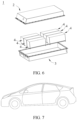
- FIG. 7 shows an electric apparatus as an example.
- the electric apparatus is a battery electric vehicle, a hybrid electric vehicle, a plug-in hybrid electric vehicle, or the like.
- a battery pack or a battery module may be used.
- the first additive is selected from the following compounds:
- the second additive is selected from the following compounds:
- lithium iron pyrophosphate powder 4.77 g of lithium carbonate, 7.47 g of ferrous carbonate, 14.84 g of ammonium dihydrogen phosphate, and 1.3 g of oxalic acid dihydrate were dissolved in 50 ml of deionized water; a resulting mixture had a pH of 5 and was stirred for 2 hours for the reaction mixture to react thoroughly; then the solution after reaction was warmed up to 80°C and maintained at that temperature for 4 hours to obtain a suspension containing Li 2 FeP 2 O 7 , and the suspension was filtered, washed with deionized water, and dried at 120°C for 4 hours to obtain a powder; and the powder was sintered at 650°C in a nitrogen atmosphere for 8 hours, naturally cooled to room temperature, and then ground to obtain Li 2 FeP 2 O 7 powder.
- lithium iron phosphate suspension 11.1 g of lithium carbonate, 34.8 g of ferrous carbonate, 34.5 g of ammonium dihydrogen phosphate, 1.3 g of oxalic acid dihydrate, and 74.6 g of sucrose (denoted as C 12 H 22 O 11 , the same applies hereinafter) were dissolved in 150 ml of deionized water to obtain a mixture, and the mixture was then stirred for 6 hours for thorough reaction; and then the solution after reaction was warmed up to 120°C and maintained at that temperature for 6 hours to obtain a suspension containing LiFePO 4 .
- the prepared lithium manganese phosphate positive electrode active material coated with two layers, conductive agent acetylene black, and binder polyvinylidene fluoride (PVDF) were added at a weight ratio of 92:2.5:5.5 to N-methylpyrrolidone (NMP), and a resulting mixture was stirred and mixed to uniformity to obtain a positive electrode slurry. Then the positive electrode slurry was uniformly applied on an aluminum foil at 0.280 g/1540.25 mm 2 , followed by drying, cold pressing, and slitting, to obtain a positive electrode plate.
- Negative electrode active material artificial graphite, hard carbon, conductive agent acetylene black, binder styrene-butadiene rubber (SBR), thickener sodium carboxymethyl cellulose (CMC-Na) were dissolved at a weight ratio of 90:5:2:2:1 in solvent deionized water, and a resulting mixture was stirred and mixed well, to obtain a negative electrode slurry.
- the negative electrode slurry was uniformly applied onto a negative electrode current collector copper foil at 0.117 g/1540.25 mm 2 , followed by drying, cold pressing, and slitting, to obtain a negative electrode plate.
- ethylene carbonate (EC)/ethyl methyl carbonate (EMC) as organic solvents were mixed well at a volume ratio of 3:7, and added with compound 1 (as a first additive, with a mass percentage of 2% in the electrolyte), compound 5 (as a second additive, with a mass percentage of 1% in the electrolyte), and LiPF6 (as an electrolytic salt, with a mass percentage of 1% in the electrolyte).
- a resulting mixture was stirred well to obtain an electrolyte.
- a commercially available PP-PE copolymer microporous film with a thickness of 20 ⁇ m and an average pore diameter of 80 nm was used.
- the positive electrode plate, separator, and negative electrode plate obtained above were stacked in order, so that the separator was placed between the positive and negative electrodes for separation, and winding was performed to obtain a jelly roll.
- the jelly roll was placed in an outer package, the electrolyte was injected, and the outer package was sealed to obtain full batteries (also referred to as "full batteries” hereinafter).
- the prepared lithium manganese phosphate positive electrode active material coated with two layers, PVDF, and acetylene black were added at a weight ratio of 90:5:5 to NMP and stirred in a drying room to obtain a slurry.
- the slurry was applied onto an aluminum foil, followed by drying and cold pressing, to obtain a positive electrode plate.
- the coating amount was 0.2 g/cm 2 and the compacted density was 2.0 g/cm 3 .
- a lithium sheet used as the negative electrode, the electrolyte, and the prepared positive electrode plate were assembled together in a button cell box to form a button battery (also referred to as "button cell” hereafter).
- Example 1-1 The preparation conditions for lithium manganese phosphate cores in Examples 1-2 to 1-6 were the same as those in Example 1-1, except that neither vanadium dichloride nor cobalt sulfate was used and that 463.4 g of ferrous carbonate, 1.6 g of dilute sulfuric acid with a concentration of 60%, 1148.9 g of ammonium dihydrogen phosphate, and 369.0 g of lithium carbonate were used during the preparation of the co-doped lithium manganese phosphate core.
- Example 1-1 the conditions were the same as those in Example 1-1, except that during the preparation of lithium iron pyrophosphate and lithium iron phosphate and during the application of the first coating layer and the second coating layer, the raw materials used were adjusted accordingly in accordance with ratios of the coating amounts shown in Table 1 to the corresponding coating amount in Example 1-1 so that the amounts of Li 2 FeP 2 O 7 /LiFePO 4 in Examples 1-2 to 1-6 were respectively 12.6 g/37.7 g, 15.7 g/47.1 g, 18.8 g/56.5 g, 22.0/66.0 g, and 25.1 g/75.4 g, and that the amount of sucrose in Examples 1-2 to 1-6 was 37.3 g.
- Example 1-7 to 1-10 were the same as those in Example 1-3 except that the amounts of sucrose were 74.6 g, 149.1 g, 186.4 g, and 223.7 g, respectively so that the corresponding coating amounts of the carbon layer as the second coating layer were 31.4 g, 62.9 g, 78.6 g, and 94.3 g, respectively.
- Example 1-7 The conditions in Examples 1-11 to 1-14 were the same as those in Example 1-7, except that the amounts of various raw materials were adjusted accordingly in accordance with the application amounts shown in Table 1 so that the amounts of Li 2 FeP 2 O 7 /LiFePO 4 were respectively 23.6 g/39.3 g, 31.4 g/31.4 g, 39.3 g/23.6 g, and 47.2 g/15.7 g during the preparation of lithium iron pyrophosphate and lithium iron phosphate.
- Example 1-15 The conditions in Example 1-15 were the same as those in Example 1-14, except that 492.80 g of ZnCO 3 was used in place of ferrous carbonate during the preparation of the co-doped lithium manganese phosphate core.
- Example 1-17 to 1-19 were the same as those in Example 1-7, except that 466.4 g of NiCO 3 , 5.0 g of zinc carbonate, and 7.2 g of titanium sulfate in place of ferrous carbonate were used during the preparation of the co-doped lithium manganese phosphate core in Example 1-16, that 455.2 g of ferrous carbonate and 8.5 g of vanadium dichloride were used during the preparation of the co-doped lithium manganese phosphate core in Example 1-17, and that 455.2 g of ferrous carbonate, 4.9 g of vanadium dichloride, and 2.5 g of magnesium carbonate were used during the preparation of the co-doped lithium manganese phosphate core in Example 1-18.
- Example 1-19 and 1-20 were the same as those in Example 1-18, except that 369.4 g of lithium carbonate and 1.05 g of dilute nitric acid with a concentration of 60% in place of dilute sulfuric acid were used during the preparation of the co-doped lithium manganese phosphate core in Example 1-19, and that 369.7 g of lithium carbonate and 0.78 g of metasilicic acid in place of dilute sulfuric acid were used during the preparation of the co-doped lithium manganese phosphate core in Example 1-20.
- Examples 1-21 and 1-22 were the same as those in Example 1-20, except that 632.0 g of manganese carbonate, 463.30 g of ferrous carbonate, 30.5 g of vanadium dichloride, 21.0 g of magnesium carbonate, and 0.78 g of metasilicic acid were used during the preparation of the co-doped lithium manganese phosphate core in Example 1-21; and that 746.9 g of manganese carbonate, 289.6 g of ferrous carbonate, 60.9 g of vanadium dichloride, 42.1 g of magnesium carbonate, and 0.78 g of metasilicic acid were used during the preparation of the co-doped lithium manganese phosphate core in Example 1-22.
- Examples 1-23 and 1-24 were the same as those in Example 1-22, except that 804.6 g of manganese carbonate, 231.7 g of ferrous carbonate, 1156.2 g of ammonium dihydrogen phosphate, 1.2 g of boric acid (mass fraction of 99.5%), and 370.8 g of lithium carbonate were used during the preparation of the co-doped lithium manganese phosphate core in Example 1-23; and that 862.1 g of manganese carbonate, 173.8 g of ferrous carbonate, 1155.1 g of ammonium dihydrogen phosphate, 1.86 g of boric acid (mass fraction of 99.5%), and 371.6 g of lithium carbonate were used during the preparation of the co-doped lithium manganese phosphate core in Example 1-24.
- Example 1-25 The conditions in Example 1-25 were the same as those in Example 1-20, except that 370.1 g of lithium carbonate, 1.56 g of metasilicic acid, and 1147.7 g of ammonium dihydrogen phosphate were used during the preparation of the co-doped lithium manganese phosphate core in Example 1-25.
- Example 1-26 The conditions in Example 1-26 were the same as those in Example 1-20, except that 368.3 g of lithium carbonate, 4.9 g of dilute sulfuric acid with a mass fraction of 60%, 919.6 g of manganese carbonate, 224.8 g of ferrous carbonate, 3.7 g of vanadium dichloride, 2.5 g of magnesium carbonate, and 1146.8 g of ammonium dihydrogen phosphate were used during the preparation of the co-doped lithium manganese phosphate core in Example 1-26.
- Example 1-27 The conditions in Example 1-27 were the same as those in Examples 1-20 except that 367.9 g of lithium carbonate, 6.5 g of dilute sulfuric acid with a concentration of 60%, and 1145.4 g of ammonium dihydrogen phosphate were used during the preparation of the co-doped lithium manganese phosphate core in Example 1-27.
- Examples 1-28 to 1-33 were the same as those in Example 1-20, except that 1034.5 g of manganese carbonate, 108.9 g of ferrous carbonate, 3.7 g of vanadium dichloride, 2.5 g of magnesium carbonate, the respective amounts of lithium carbonate of 367.6 g, 367.2 g, 366.8 g, 366.4 g, 366.0 g, and 332.4 g, the respective amounts of ammonium dihydrogen phosphate of 1144.5 g, 1143.4 g, 1142.2 g, 1141.1 g, 1139.9 g, and 1138.8 g, and the respective amounts of dilute sulfuric acid with a concentration of 60% of 8.2 g, 9.8 g, 11.4 g, 13.1 g, 14.7 g, and 16.3 g were used during the preparation of the co-doped lithium manganese phosphate core in Examples 1-28 to 1-33.
- Example 1-1 The conditions were the same as those in Example 1-1, except that during the preparation of lithium iron pyrophosphate (Li 2 FeP 2 O 7 ), the sintering temperature in the powder sintering step was 550°C and the sintering time was 1 hour to control the crystallinity of Li 2 FeP 2 O 7 to be 30%, and that during the preparation of lithium iron phosphate (LiFePO 4 ), the sintering temperature in the coating sintering step was 650°C and the sintering time was 2 hours to control the crystallinity of LiFePO 4 to be 30%.
- Example 1-1 The conditions were the same as those in Example 1-1, except that during the preparation of lithium iron pyrophosphate (Li 2 FeP 2 O 7 ), the sintering temperature in the powder sintering step was 550°C and the sintering time was 2 hours to control the crystallinity of Li 2 FeP 2 O 7 to be 50%, and that during the preparation of lithium iron phosphate (LiFePO 4 ), the sintering temperature in the coating sintering step was 650°C and the sintering time was 3 hours to control the crystallinity of LiFePO 4 to be 50%.
- Li 2 FeP 2 O 7 lithium iron pyrophosphate
- the sintering temperature in the coating sintering step was 650°C and the sintering time was 3 hours to control the crystallinity of LiFePO 4 to be 50%.
- Example 1-1 The conditions were the same as those in Example 1-1, except that during the preparation of lithium iron pyrophosphate (Li 2 FeP 2 O 7 ), the sintering temperature in the powder sintering step was 600°C and the sintering time was 3 hours to control the crystallinity of Li 2 FeP 2 O 7 to be 70%, and that during the preparation of lithium iron phosphate (LiFePO 4 ), the sintering temperature in the coating sintering step was 650°C and the sintering time was 4 hours to control the crystallinity of LiFePO 4 to be 70%.
- Example 1-1 The conditions were the same as those in Example 1-1, except that during the preparation of lithium iron pyrophosphate (Li 2 FeP 2 O 7 ), the sintering temperature in the powder sintering step was 650°C and the sintering time was 4 hours to control the crystallinity of Li 2 FeP 2 O 7 to be 100%, and that during the preparation of lithium iron phosphate (LiFePO 4 ), the sintering temperature in the coating sintering step was 700°C and the sintering time was 6 hours to control the crystallinity of LiFePO 4 to be 100%.
- Li 2 FeP 2 O 7 lithium iron pyrophosphate
- the sintering temperature in the coating sintering step was 700°C and the sintering time was 6 hours to control the crystallinity of LiFePO 4 to be 100%.
- Example 3-1 to 3-12 were the same as those in Example 1-1, except that during the preparation of Fe, Co, and V co-doped manganese oxalate particles, the heating temperature and stirring time in the reactor in Example 3-1 were respectively 60°C and 120 minutes; that the heating temperature and stirring time in the reactor in Example 3-2 were respectively 70°C and 120 minutes; that the heating temperature and stirring time in the reactor in Example 3-3 were respectively 80°C and 120 minutes; that the heating temperature and stirring time in the reactor in Example 3-4 were respectively 90°C and 120 minutes; that the heating temperature and stirring time in the reactor in Example 3-5 were respectively 100°C and 120 minutes; that the heating temperature and stirring time in the reactor in Example 3-6 were respectively 110°C and 120 minutes; that the heating temperature and stirring time in the reactor in Example 3-7 were respectively 120°C and 120 minutes; that the heating temperature and stirring time in the reactor in Example 3-8 were respectively 130°C and 120 minutes; that the heating temperature and stirring time in the reactor in Example 3-9 were respectively 100°C and 60 minutes; that the heating temperature and
- Examples 4-1 to 4-4 The conditions were the same as those in Example 1-7, except that during the preparation of lithium iron pyrophosphate (Li 2 FeP 2 O 7 ), the drying temperature and drying time in the drying step were respectively 100°C/4 h, 150°C/6 h, 200°C/6 h, and 200°C/6 h; and that during the preparation of lithium iron pyrophosphate (Li 2 FeP 2 O 7 ), the sintering temperature and sintering time in the sintering step were respectively 700°C/6 h, 700°C/6 h, 700°C/6 h, and 600°C/6 h.
- Examples 4-5 to 4-7 The conditions were the same as those in Example 1-12, except that during the coating, the drying temperature and drying time in the drying step were respectively 150°C/6 h, 150°C/6 h, and 150°C/6 h; and that during the coating, the sintering temperature and sintering time in the sintering step were respectively 600°C/4 h, 600°C/6 h, and 800°C/8 h.
- Comparative example 2 The conditions in Comparative example 2 were the same as those in Comparative example 1, except that 689.5 g of manganese carbonate was used and that 463.3 g of ferrous carbonate was additionally added.
- Comparative example 3 The conditions in Comparative example 3 were the same as those in Comparative example 1, except that 1148.9 g of ammonium dihydrogen phosphate and 369.0 g of lithium carbonate were used and that 1.6 g of dilute sulfuric acid with a concentration of 60% was additionally added.
- Comparative example 4 The conditions in Comparative example 4 were the same as those in Comparative example 1, except that 689.5 g of manganese carbonate, 1148.9 g of ammonium dihydrogen phosphate, and 369.0 g of lithium carbonate were used and that 463.3 g of ferrous carbonate and 1.6 g of dilute sulfuric acid with a concentration of 60% were additionally added.
- Comparative example 5 The conditions in Comparative example 5 were the same as those in Comparative example 4, except that the following step was additionally added: Preparation of lithium iron pyrophosphate powder: 9.52 g of lithium carbonate, 29.9 g of ferrous carbonate, 29.6 g of ammonium dihydrogen phosphate, and 32.5 g of oxalic acid dihydrate were dissolved in 50 ml of deionized water; a resulting mixture had a pH of 5 and was stirred for 2 hours for the reaction mixture to react thoroughly; then the solution after reaction was warmed up to 80°C and maintained at that temperature for 4 hours to obtain a suspension containing Li 2 FeP 2 O 7 , and the suspension was filtered, washed with deionized water, and dried at 120°C for 4 hours to obtain a powder; and the powder was sintered at 500°C in a nitrogen atmosphere for 4 hours, naturally cooled to room temperature, and then grounded to control the crystallinity of Li 2 FeP 2 O 7 to be 5%, and that
- Comparative example 6 The conditions in Comparative example 6 were the same as those in Comparative example 4, except that the following step was additionally added: Preparation of lithium iron phosphate suspension: 14.7 g of lithium carbonate, 46.1 g of ferrous carbonate, 45.8 g of ammonium dihydrogen phosphate, and 50.2 g of oxalic acid dihydrate were dissolved in 500 ml of deionized water, and a resulting mixture was stirred for 6 hours for the mixture to react thoroughly; and then the solution after reaction was warmed up to 120°C and maintained at that temperature for 6 hours to obtain a suspension containing Li 2 FeP 2 O 7 , and during the preparation of lithium iron phosphate (LiFePO 4 ), the sintering temperature in the coating sintering step was 600°C and the sintering time was 4 hours to control the crystallinity of LiFePO 4 to be 8%, and that 62.8 g of LiFePO 4 was used when the carbon-coated material was being prepared.
- lithium iron pyrophosphate powder 2.38 g of lithium carbonate, 7.5 g of ferrous carbonate, 7.4 g of ammonium dihydrogen phosphate, and 8.1 g of oxalic acid dihydrate were dissolved in 50 ml of deionized water; a resulting mixture had a pH of 5 and was stirred for 2 hours for the reaction mixture to react thoroughly; then the solution after reaction was warmed up to 80°C and maintained at that temperature for 4 hours to obtain a suspension containing Li 2 FeP 2 O 7 , and the suspension was filtered, washed with deionized water, and dried at 120°C for 4 hours to obtain a powder; and the powder was sintered at 500°C in a nitrogen atmosphere for 4 hours, naturally cooled to room temperature, and then ground to control the crystallinity of Li 2 FeP 2 O 7 to be 5%.
- lithium iron phosphate suspension 11.1 g of lithium carbonate, 34.7 g of ferrous carbonate, 34.4 g of ammonium dihydrogen phosphate, 37.7 g of oxalic acid dihydrate, and 37.3 g of sucrose (denoted as C 12 H 22 O 11 , the same applies hereinafter) were dissolved in 1500 ml of deionized water to obtain a mixture, and the mixture was then stirred for 6 hours for thorough reaction; and then the solution after reaction was warmed up to 120°C and maintained at that temperature for 6 hours to obtain a suspension containing LiFePO 4 .
- lithium iron pyrophosphate powder prepared was added to the suspension containing lithium iron phosphate (LiFePO 4 ) and sucrose.
- the conditions in Comparative example 7 were the same as those in Comparative example 4, except that during the preparation, the sintering temperature in the coating sintering step was 600°C and the sintering time was 4 hours to control the crystallinity of LiFePO 4 to be 8%.
- the conditions were the same as those in Comparative examples 1 to 7, except that during the preparation of lithium iron pyrophosphate (Li 2 FeP 2 O 7 ), the drying temperature and drying time in the drying step in Comparative examples 8-10 were respectively 80°C/3 h, 80°C/3 h, and 80°C/3 h; that the sintering temperature and sintering time in the sintering step during the preparation of lithium iron pyrophosphate (Li 2 FeP 2 O 7 ) in Comparative examples 8-10 were respectively 400°C/3 h, 400°C/3 h, and 350°C/2 h; that the drying temperature and drying time in the drying step during the preparation of lithium iron phosphate (LiFePO 4 ) in Comparative example 11 were 80°C/3 h; and that the amounts of Li 2 FeP 2 O 7 and LiFePO 4 in Comparative examples 8-11 were respectively 47.2 g/15.7 g, 15.7 g/47.2 g, 62.8 g/0 g, and 0 g/62.8 g
- the prepared button cell was charged to 4.3 V at 0.1C under a voltage of 2.5 V-4.3 V, then charged at constant voltage of 4.3 V until the current is less than or equal to 0.05 mA, left standing for 5 min, then discharged to 2.0 V at 0.1C, and a discharge capacity at this moment was an initial gram capacity and recorded as D0.
- the prepared button cell was left standing for 5 minutes at a constant temperature of 25°C, discharged to 2.5 V at 0.1C, left standing for 5 minutes, charged to 4.3 V at 0.1C, and then charged at a constant voltage of 4.3 V until the current is less than or equal to 0.05 mA.
- the button cell was discharged to 2.5 V at 0.1C, a discharge capacity at this moment was recorded as an initial gram capacity, denoted as D0, discharge energy was recorded as initial energy, denoted as E0, and the average discharge voltage V of the button cell was E0/D0.
- the prepared full batteries in 100% state of charge (SOC) were stored at 60°C.
- the open circuit voltages (OCV) and alternating current internal resistances (IMP) of the cells were measured before, during, and after storage to monitor the SOCs, and the volumes of the cells were measured.
- the full batteries were removed after every 48 hours of storage and left standing for 1 hour. Then the open circuit voltage (OCV) and internal resistance (IMP) were measured, and the cell volumes were measured by a drainage method after the batteries were cooled to room temperature.
- a scale that automatically performs unit conversion on dial data was used to separately measure a weight of the cell, denoted as F 1 , then the cell was completely placed into deionized water (density known to be 1 g/cm 3 ), and the weight of the cell at this moment was measured as F 2 .
- the buoyant force experienced by the cell denoted as F_buoyancy, is calculated as F 1 -F 2 .
- F_buoyancy ⁇ ⁇ g ⁇ V displacement
- the residual capacity was measured for the cells.
- the full batteries were charged to 4.3 V at 1C under a voltage of 2.5 V-4.3 V, then charged at constant voltage of 4.3 V until the current is less than or equal to 0.05 mA, left standing for 5 min, and the charge capacity at this moment was recorded as the residual capacity of the cell.
- the prepared full batteries were charged to 4.3 V at 1C under a voltage of 2.5 V-4.3 V at a constant temperature of 45°C, and then charged at constant voltage of 4.3 V until the current is less than or equal to 0.05 mA. After standing for 5 min, the full batteries were discharged to 2.5 V at 1C, and the discharge capacity at this moment was recorded as D0. The charge/discharge cycle was repeated until the discharge capacity was reduced to 80% of D0. The number of cycles the battery has undergone at this moment was recorded.
- the prepared positive electrode active material samples were placed in an XRD instrument (model: Bruker D8 Discover), and the samples were tested at 1°/min.
- the test data were organized and analyzed, and the lattice constants a0, b0, c0, and v0 (where a0, b0, and c0 represent the lengths of faces of the crystal cell, and v0 denotes the volume of the crystal cell, which can be obtained directly from XRD refinement results) at this moment were calculated with reference to standard PDF cards.
- the positive electrode active material sample was used for preparation of a button cell using the foregoing preparation method of button cell, and the button cell was charged at a small rate of 0.05C until the current was reduced to 0.01C.
- the positive electrode plate in the button cell was then removed and soaked in dimethyl carbonate (DMC) for 8 hours, then dried and powder scraped, and particles with a particle size less than 500 nm were sifted out.
- Samples were taken and their crystal cell volumes v1 were calculated in the same way as the fresh samples under test above, and (v0-v1)/v0 ⁇ 100% was taken as their lattice change rates (crystal cell volume change rate) before and after complete lithium deintercalation and intercalation were shown in the table.
- the Li/Mn antisite defect concentration was obtained by comparing the XRD results in the "lattice change rate measurement method" with the standard crystal PDF (Powder Diffraction File) cards. Specifically, the XRD results in the "lattice change rate measurement method” were imported into the general structural analysis system (GSAS) software for automatic obtaining of refinement results that contain the occupancy of the different atoms, and the Li/Mn antisite defect concentration was obtained by reading the refinement results.
- GSAS general structural analysis system
- the battery was then disassembled, the negative electrode plate was removed, and 30 discs with a unit area (1540.25 mm 2 ) were randomly taken on the negative electrode plate and tested by using Agilent ICP-OES730 for inductively coupled plasma atomic emission spectroscopy (ICP).
- the amounts of Fe if the Mn site of the positive electrode active material was doped with Fe
- Mn were calculated from the ICP results, so as to calculate the amount of Mn (and Fe doping at the Mn site) dissolved after cycling.
- the test standard is in accordance with EPA-6010D-2014.
- the total scattering intensity was a sum of scattering intensities of substances in the entire space and was only related to the intensity of the primary rays, the chemical structure, a total number of electrons participating in the diffraction, that is, the mass, and not to the order state of the sample; then separating crystalline scattering from non-crystalline scattering in a diffraction pattern, where the crystallinity is a ratio of an intensity of the crystalline scattering to the total scattering intensity.
- each prepared positive electrode active material powder was taken and placed into a 50 mL test tube, 10 mL of alcohol with a mass fraction of 75% was injected into the test tube and then fully stirred and dispersed for 30 minutes, then an appropriate amount of the solution was taken with a clean disposable plastic pipette and added dropwise on a 300 mesh copper grid, and in this case, part of the powder would remain on the copper grid.
- the copper grid with the sample was transferred to the TEM (Talos F200s G2) sample cavity for testing, and original TEM test images were obtained and saved in an original image format (xx.dm3).
- Example 1-3 and Examples 1-7 to 1-10 it can be learned from Example 1-3 and Examples 1-7 to 1-10 that as the amount of the second coating layer increases from 1% to 6%, in the resulting material, the Li/Mn antisite defect concentration is gradually decreased, the amount of Fe and manganese ions dissolved after cycling is gradually decreased, and the safety performance and 45°C cycling performance of the corresponding battery are improved, but the button cell gram capacity is slightly decreased.
- the corresponding battery has the best overall performance when the total amount of the second coating layer is 3-5% by weight.
- Example 3-1 60 120 5.6 2.4 -1.98 42 155.5 3.68 4.8 1157
- Example 3-2 70 120 4.8 1.9 -1.98 31 156.0 3.70 4.0 1263
- Example 3-3 80 120 3.7 1.3 -1.98 24 156.7 3.73 3.2 1339
- Example 3-4 90 120 2.9 1.1 -1.98 14 158.1 3.76 2.6 1370
- Example 3-5 100 120 2.5 0.5 -1.98 8 158.8 3.79 2.0 1393
- Example 3-6 110 120 2.8 1.2 -1.98 16 157.0 3.74 3.1 1320
- Example 3-7 120 120 3.7 2.1 -1.98 32 155.1 3.70
- the temperature in the reactor and the stirring time are the parameters used during the preparation of element A doped manganese oxalate (that is, step (1)).
- Type of doping element and doping amount Li 0.999 Mn 0.60 Fe 0.393 V 0.004 Co 0.003 sP 0.999 S 0.01 O 4 .
- the positive electrode active materials, button cells, and full batteries were prepared in the same manner as those in Example 1-18, but the compositions of the electrolyte were changed, as shown in Table 5 below.
- Example 5 17 155.1 3.80 3 1101
- Example 6 154.2 3.79 2.2 1260
- Example 7 30 152.5 3.79 4.1 1042
- Example 8 7 151.1 3.78 2.1 1067
- Example 9 56 147.1 3.77 5.6
- Example 10 145.6 3.76 2 943
- Example 11 123 143.4 3.76 6.5 880
- Example 12 6 142.5 3.75 2 856
- Example 13 12 155.1 3.80 2.6 1267
- Example 14 8 154.2 3.79 2.1 1291 Example 15 21 154.5 3.78 3.5 1158
- Example 16 7 153.1 3.78 2 1190
- Example 17 30 148.8 3.77 4.7 1054
- Example 18 6 147.0 3.76 2.0 1089
- Example 19 20 155.1 3.79 2.8 1267
- Example 20 154.8 3.78 2.1 1299
- Example 21 56 153.1 3.78 3.9 11
- electrolyte in full batteries of Examples 1-1 to 1-33, 2-1 to 2-4, 3-1 to 3-12, and 4-1 to 4-4 replaced by an electrolyte obtained by mixing organic solvents ethylene carbonate (EC) and ethyl methyl carbonate (EMC) at a volume ratio of 3:7 well, adding and dissolving 12.5% by weight (based on the weight of the organic solvents) LiPF 6 into the organic solvents, and stirring the mixture well, and the electrolyte in button cells in the foregoing examples replaced by an electrolyte with 1 mol/L LiPF 6 in a solution containing ethylene carbonate (EC), diethyl carbonate (DEC), dimethyl carbonate (DMC) at a volume ratio of 1:1:1, the amount of Fe and manganese ions dissolved (ppm), button cell gram capacity at 0.1C (mAh/g), average discharge voltage of button cell (V), number of cycles at 80% capacity retention rate at 45°C, and cell swelling rate after storage at 60°C (%) of
- compositions of the electrolyte in this application can further improve the energy density and cycling performance of the secondary battery.
Landscapes
- Chemical & Material Sciences (AREA)
- General Chemical & Material Sciences (AREA)
- Chemical Kinetics & Catalysis (AREA)
- Electrochemistry (AREA)
- Engineering & Computer Science (AREA)
- Inorganic Chemistry (AREA)
- Manufacturing & Machinery (AREA)
- Composite Materials (AREA)
- Materials Engineering (AREA)
- General Physics & Mathematics (AREA)
- Condensed Matter Physics & Semiconductors (AREA)
- Physics & Mathematics (AREA)
- Crystallography & Structural Chemistry (AREA)
- Battery Electrode And Active Subsutance (AREA)
- Secondary Cells (AREA)
Applications Claiming Priority (1)
| Application Number | Priority Date | Filing Date | Title |
|---|---|---|---|
| PCT/CN2022/084865 WO2023184498A1 (zh) | 2022-04-01 | 2022-04-01 | 二次电池、电池模块、电池包和用电装置 |
Publications (2)
| Publication Number | Publication Date |
|---|---|
| EP4485576A1 true EP4485576A1 (de) | 2025-01-01 |
| EP4485576A4 EP4485576A4 (de) | 2025-03-19 |
Family
ID=88198802
Family Applications (1)
| Application Number | Title | Priority Date | Filing Date |
|---|---|---|---|
| EP22934332.2A Pending EP4485576A4 (de) | 2022-04-01 | 2022-04-01 | Sekundärbatterie, batteriemodul, batteriepack und elektrische vorrichtung |
Country Status (4)
| Country | Link |
|---|---|
| US (1) | US20250015274A1 (de) |
| EP (1) | EP4485576A4 (de) |
| CN (1) | CN117321800B (de) |
| WO (1) | WO2023184498A1 (de) |
Cited By (3)
| Publication number | Priority date | Publication date | Assignee | Title |
|---|---|---|---|---|
| EP4468406A4 (de) * | 2022-04-29 | 2025-04-02 | Contemporary Amperex Technology (Hong Kong) Limited | Sekundärbatterie, batteriemodul, batteriepack und elektrische vorrichtung |
| EP4425607A4 (de) * | 2022-04-29 | 2025-04-09 | Contemporary Amperex Technology (Hong Kong) Limited | Sekundärbatterie, batteriemodul, batteriepack und elektrische vorrichtung |
| EP4407732A4 (de) * | 2022-04-29 | 2025-04-16 | Contemporary Amperex Technology (Hong Kong) Limited | Sekundärbatterie, batteriemodul, batteriepack und elektrische vorrichtung |
Families Citing this family (4)
| Publication number | Priority date | Publication date | Assignee | Title |
|---|---|---|---|---|
| CN120600883A (zh) * | 2024-03-04 | 2025-09-05 | 蔚来汽车科技(安徽)有限公司 | 二次电池及装置 |
| CN120784293A (zh) * | 2024-04-02 | 2025-10-14 | 宁德时代新能源科技股份有限公司 | 正极活性材料及其制备方法、二次电池和用电装置 |
| CN118867395B (zh) * | 2024-09-25 | 2025-02-18 | 深圳市豪鹏科技股份有限公司 | 电解液添加剂和电解液及高镍二次电池 |
| CN119944039B (zh) * | 2024-12-31 | 2025-11-11 | 深圳新宙邦科技股份有限公司 | 一种锂离子电池 |
Family Cites Families (15)
| Publication number | Priority date | Publication date | Assignee | Title |
|---|---|---|---|---|
| WO2011013243A1 (ja) * | 2009-07-31 | 2011-02-03 | トヨタ自動車株式会社 | 正極活物質及びその製造方法 |
| CN103069624B (zh) * | 2010-07-01 | 2016-06-22 | 夏普株式会社 | 正极活性材料、正极和非水二次电池 |
| JP2014056722A (ja) * | 2012-09-13 | 2014-03-27 | Asahi Glass Co Ltd | リン酸化合物、二次電池用正極材料、および二次電池の製造方法 |
| CN103872320A (zh) * | 2014-03-12 | 2014-06-18 | 张萍 | 一种钕镍硼掺杂磷酸锰锂复合正极材料的制备方法 |
| CN104577115A (zh) * | 2014-12-26 | 2015-04-29 | 青海时代新能源科技有限公司 | 一种锂离子电池正极材料、其制备方法及应用 |
| CN106816600B (zh) * | 2015-11-30 | 2020-12-25 | 比亚迪股份有限公司 | 一种磷酸锰铁锂类材料及其制备方法以及电池浆料和正极与锂电池 |
| CN106099171A (zh) * | 2016-07-13 | 2016-11-09 | 东莞市凯欣电池材料有限公司 | 一种锂离子动力电池电解液及锂离子动力电池 |
| CN106058225A (zh) * | 2016-08-19 | 2016-10-26 | 中航锂电(洛阳)有限公司 | 核壳结构LiMn1‑xFexPO4正极材料及其制备方法、锂离子电池 |
| CN109301174B (zh) * | 2017-07-24 | 2020-11-13 | 宁德时代新能源科技股份有限公司 | 正极材料及其制备方法及锂二次电池 |
| CN107968195A (zh) * | 2017-11-22 | 2018-04-27 | 合肥国轩高科动力能源有限公司 | 一种磷酸铁锂包覆的富锂正极材料及其制备方法 |
| CN113130997B (zh) * | 2018-05-17 | 2022-07-05 | 宁德时代新能源科技股份有限公司 | 锂离子电池及其制备方法与包含锂离子电池的电动汽车 |
| CN112151773B (zh) * | 2019-06-26 | 2022-05-24 | 中国科学院物理研究所 | 一种正极活性材料及其制备方法和锂电池 |
| CN112234252A (zh) * | 2019-07-15 | 2021-01-15 | 杉杉新材料(衢州)有限公司 | 一种高电压用宽温型锂离子电池非水电解液及锂离子电池 |
| CN111029653A (zh) * | 2019-12-20 | 2020-04-17 | 东莞市杉杉电池材料有限公司 | 一种锂离子电池电解液及含有该电解液的锂离子电池 |
| CN111668547B (zh) * | 2020-06-30 | 2021-09-24 | 远景动力技术(江苏)有限公司 | 非水电解液及使用了其的蓄电装置 |
-
2022
- 2022-04-01 EP EP22934332.2A patent/EP4485576A4/de active Pending
- 2022-04-01 WO PCT/CN2022/084865 patent/WO2023184498A1/zh not_active Ceased
- 2022-04-01 CN CN202280034709.6A patent/CN117321800B/zh active Active
-
2024
- 2024-09-12 US US18/882,772 patent/US20250015274A1/en active Pending
Cited By (3)
| Publication number | Priority date | Publication date | Assignee | Title |
|---|---|---|---|---|
| EP4468406A4 (de) * | 2022-04-29 | 2025-04-02 | Contemporary Amperex Technology (Hong Kong) Limited | Sekundärbatterie, batteriemodul, batteriepack und elektrische vorrichtung |
| EP4425607A4 (de) * | 2022-04-29 | 2025-04-09 | Contemporary Amperex Technology (Hong Kong) Limited | Sekundärbatterie, batteriemodul, batteriepack und elektrische vorrichtung |
| EP4407732A4 (de) * | 2022-04-29 | 2025-04-16 | Contemporary Amperex Technology (Hong Kong) Limited | Sekundärbatterie, batteriemodul, batteriepack und elektrische vorrichtung |
Also Published As
| Publication number | Publication date |
|---|---|
| CN117321800B (zh) | 2025-09-23 |
| WO2023184498A1 (zh) | 2023-10-05 |
| EP4485576A4 (de) | 2025-03-19 |
| CN117321800A (zh) | 2023-12-29 |
| US20250015274A1 (en) | 2025-01-09 |
Similar Documents
| Publication | Publication Date | Title |
|---|---|---|
| US20240282963A1 (en) | Positive electrode active material, positive electrode plate, secondary battery, battery module, battery pack and power consuming device | |
| CN117378059B (zh) | 正极活性材料及其制备方法、正极极片、二次电池、电池模块、电池包和用电装置 | |
| EP4485576A1 (de) | Sekundärbatterie, batteriemodul, batteriepack und elektrische vorrichtung | |
| CN116964774B (zh) | 正极活性材料、正极极片、二次电池、电池模块、电池包和用电装置 | |
| CN117461158B (zh) | 正极活性材料、正极极片、二次电池、电池模块、电池包和用电装置 | |
| EP4276928A1 (de) | Positives aktivmaterial, herstellungsverfahren dafür, positive elektrodenplatte mit positivem aktivmaterial sowie sekundärbatterie und elektrische vorrichtung | |
| EP4546454A1 (de) | Positivelektrodenaktivmaterial, herstellungsverfahren für positivelektrodenaktivmaterial, positivelektrodenplatte, sekundärbatterie, batteriemodul, batteriepack und elektrische vorrichtung | |
| CN116830314A (zh) | 二次电池、电池模块、电池包和用电装置 | |
| CN116897453B (zh) | 二次电池、电池模块、电池包和用电装置 | |
| US12519127B2 (en) | Secondary battery, battery module, battery pack, and electric device | |
| US20250062415A1 (en) | Secondary battery, battery module, battery pack, and electric apparatus | |
| US12183917B2 (en) | Secondary battery comprising positive electrode plate and non-aqueous electrolyte solution | |
| EP4270575A1 (de) | Positivelektrodenplatte, sekundärbatterie, batteriemodul, batteriepack und elektrische vorrichtung | |
| US20240254003A1 (en) | Positive electrode active material with core-shell structure and preparation method thereof, positive electrode plate, secondary battery, battery module, battery pack, and electric apparatus | |
| CN117441251A (zh) | 二次电池、电池模块、电池包和用电装置 | |
| US20240120480A1 (en) | Positive electrode active material and preparation method thereof, positive electrode plate, secondary battery, battery module, battery pack, and electric apparatus | |
| EP4421917A1 (de) | Positivelektrodenaktivmaterial, herstellungsverfahren dafür und positivelektrodenplatte damit sowie sekundärbatterie und elektrische vorrichtung | |
| CN119731801A (zh) | 一种新型正极极片、电池及用电装置 | |
| EP4318704A1 (de) | Sekundärbatterie, batteriemodul, batteriepack und elektrische vorrichtung | |
| EP4425613A1 (de) | Positivelektrodenaktivmaterial, positivelektrodenfolie, sekundärbatterie, batteriemodul, batteriepack und elektrische vorrichtung | |
| CN119744454B (zh) | 一种正极极片、电池和用电装置 | |
| CN118661294A (zh) | 正极活性材料、其制备方法以及包含其的正极极片、二次电池及用电装置 |
Legal Events
| Date | Code | Title | Description |
|---|---|---|---|
| STAA | Information on the status of an ep patent application or granted ep patent |
Free format text: STATUS: THE INTERNATIONAL PUBLICATION HAS BEEN MADE |
|
| PUAI | Public reference made under article 153(3) epc to a published international application that has entered the european phase |
Free format text: ORIGINAL CODE: 0009012 |
|
| STAA | Information on the status of an ep patent application or granted ep patent |
Free format text: STATUS: REQUEST FOR EXAMINATION WAS MADE |
|
| 17P | Request for examination filed |
Effective date: 20240923 |
|
| AK | Designated contracting states |
Kind code of ref document: A1 Designated state(s): AL AT BE BG CH CY CZ DE DK EE ES FI FR GB GR HR HU IE IS IT LI LT LU LV MC MK MT NL NO PL PT RO RS SE SI SK SM TR |
|
| A4 | Supplementary search report drawn up and despatched |
Effective date: 20250214 |
|
| RIC1 | Information provided on ipc code assigned before grant |
Ipc: H01M 4/02 20060101ALN20250210BHEP Ipc: C01B 25/45 20060101ALN20250210BHEP Ipc: H01M 10/0567 20100101ALI20250210BHEP Ipc: H01M 10/0525 20100101ALI20250210BHEP Ipc: H01M 4/36 20060101ALI20250210BHEP Ipc: H01M 4/136 20100101ALI20250210BHEP Ipc: H01M 4/62 20060101ALI20250210BHEP Ipc: H01M 4/58 20100101AFI20250210BHEP |
|
| DAV | Request for validation of the european patent (deleted) | ||
| DAX | Request for extension of the european patent (deleted) | ||
| GRAP | Despatch of communication of intention to grant a patent |
Free format text: ORIGINAL CODE: EPIDOSNIGR1 |
|
| STAA | Information on the status of an ep patent application or granted ep patent |
Free format text: STATUS: GRANT OF PATENT IS INTENDED |
|
| RIC1 | Information provided on ipc code assigned before grant |
Ipc: H01M 4/58 20100101AFI20260323BHEP Ipc: H01M 4/62 20060101ALI20260323BHEP Ipc: H01M 4/136 20100101ALI20260323BHEP Ipc: H01M 4/36 20060101ALI20260323BHEP Ipc: H01M 10/0525 20100101ALI20260323BHEP Ipc: H01M 10/0567 20100101ALI20260323BHEP Ipc: C01B 25/45 20060101ALN20260323BHEP Ipc: H01M 4/02 20060101ALN20260323BHEP |