EP4485694A1 - Unité de métasurface et station de base associée - Google Patents
Unité de métasurface et station de base associée Download PDFInfo
- Publication number
- EP4485694A1 EP4485694A1 EP23773557.6A EP23773557A EP4485694A1 EP 4485694 A1 EP4485694 A1 EP 4485694A1 EP 23773557 A EP23773557 A EP 23773557A EP 4485694 A1 EP4485694 A1 EP 4485694A1
- Authority
- EP
- European Patent Office
- Prior art keywords
- phase shifter
- power divider
- transmission line
- switch
- port
- Prior art date
- Legal status (The legal status is an assumption and is not a legal conclusion. Google has not performed a legal analysis and makes no representation as to the accuracy of the status listed.)
- Pending
Links
Images



Classifications
-
- H—ELECTRICITY
- H01—ELECTRIC ELEMENTS
- H01Q—ANTENNAS, i.e. RADIO AERIALS
- H01Q3/00—Arrangements for changing or varying the orientation or the shape of the directional pattern of the waves radiated from an antenna or antenna system
- H01Q3/44—Arrangements for changing or varying the orientation or the shape of the directional pattern of the waves radiated from an antenna or antenna system varying the electric or magnetic characteristics of reflecting, refracting, or diffracting devices associated with the radiating element
- H01Q3/46—Active lenses or reflecting arrays
-
- H—ELECTRICITY
- H01—ELECTRIC ELEMENTS
- H01P—WAVEGUIDES; RESONATORS, LINES, OR OTHER DEVICES OF THE WAVEGUIDE TYPE
- H01P1/00—Auxiliary devices
- H01P1/18—Phase-shifters
- H01P1/184—Strip line phase-shifters
-
- H—ELECTRICITY
- H01—ELECTRIC ELEMENTS
- H01Q—ANTENNAS, i.e. RADIO AERIALS
- H01Q1/00—Details of, or arrangements associated with, antennas
- H01Q1/12—Supports; Mounting means
- H01Q1/22—Supports; Mounting means by structural association with other equipment or articles
- H01Q1/24—Supports; Mounting means by structural association with other equipment or articles with receiving set
- H01Q1/241—Supports; Mounting means by structural association with other equipment or articles with receiving set used in mobile communications, e.g. GSM
- H01Q1/246—Supports; Mounting means by structural association with other equipment or articles with receiving set used in mobile communications, e.g. GSM specially adapted for base stations
-
- H—ELECTRICITY
- H01—ELECTRIC ELEMENTS
- H01Q—ANTENNAS, i.e. RADIO AERIALS
- H01Q15/00—Devices for reflection, refraction, diffraction or polarisation of waves radiated from an antenna, e.g. quasi-optical devices
- H01Q15/0006—Devices acting selectively as reflecting surface, as diffracting or as refracting device, e.g. frequency filtering or angular spatial filtering devices
- H01Q15/0086—Devices acting selectively as reflecting surface, as diffracting or as refracting device, e.g. frequency filtering or angular spatial filtering devices said selective devices having materials with a synthesized negative refractive index, e.g. metamaterials or left-handed materials
-
- H—ELECTRICITY
- H01—ELECTRIC ELEMENTS
- H01Q—ANTENNAS, i.e. RADIO AERIALS
- H01Q15/00—Devices for reflection, refraction, diffraction or polarisation of waves radiated from an antenna, e.g. quasi-optical devices
- H01Q15/14—Reflecting surfaces; Equivalent structures
-
- H—ELECTRICITY
- H01—ELECTRIC ELEMENTS
- H01Q—ANTENNAS, i.e. RADIO AERIALS
- H01Q21/00—Antenna arrays or systems
- H01Q21/24—Combinations of antenna units polarised in different directions for transmitting or receiving circularly and elliptically polarised waves or waves linearly polarised in any direction
- H01Q21/245—Combinations of antenna units polarised in different directions for transmitting or receiving circularly and elliptically polarised waves or waves linearly polarised in any direction provided with means for varying the polarisation
Definitions
- the present disclosure relates to but is not limited to the field of communication, in particular to a metasurface unit and a base station.
- An artificial electromagnetic metasurface is an array of metasurface units arranged periodically, which can change propagation characteristics of electromagnetic waves and realize some special functions. For example, if a specific phase difference is designed between a reflected wave and an incident wave of each unit, the array of metasurface units can achieve an electromagnetic beam shaping function with a specific angle.
- the traditional artificial electromagnetic metasurface is a static structure, and its electromagnetic characteristics can not be changed, which can not meet current communication requirements.
- a concept of programmable metasurface is put forward.
- a resonant unit of the metasurface unit is provided with a radio frequency (RF) switch, and a resonant frequency of a signal is adjusted through different states of the RF switch, thereby adjusting and controlling a reflection phase.
- the metasurface presents dynamic electromagnetic characteristics, thus realizing a programmable multi-beam shaping function.
- a parameter fluctuation of the RF switch can easily cause a resonance frequency shift of the resonant unit and affect a phase modulation accuracy of the metasurface unit.
- a combination of the resonant unit and a phase shifter is usually adopted, and the RF switch is arranged in the phase shifter.
- the resonant unit and the RF switch are separated, it is necessary to configure a phase shifter for each polarized signal, therefore the hardware cost is high.
- a metasurface unit and a base station are disclosed in embodiments of the present disclosure.
- an embodiment provides a metasurface unit, which includes a resonant unit, where the resonant unit is configured to receive two polarized incident signals or radiate two polarized reflected signals; a power divider, which is connected to the resonant unit, where the power divider is configured to combine the two polarized incident signals input by the resonant unit into a combined signal, and/or divide a reflected signal input by a phase shifter into the two polarized reflected signals and output the two polarized reflected signals to the resonant unit; and the phase shifter, which is connected to the power divider, where the phase shifter is configured to perform phase modulation on the combined signal input by the power divider and output the reflected signal obtained by the phase modulation to the power divider.
- an embodiment provides a base station, which includes the metasurface unit according to the first aspect of the present disclosure.
- the metasurface unit includes a resonant unit, where the resonant unit is configured to receive two polarized incident signals or radiate two polarized reflected signals; a power divider, which is connected to the resonant unit, where the power divider is configured to combine the two polarized incident signals input by the resonant unit into a combined signal, and/or divide a reflected signal input by a phase shifter into the two polarized reflected signals and output the two polarized reflected signals to the resonant unit; and the phase shifter, which is connected to the power divider, where the phase shifter is configured to perform phase modulation on the combined signal input by the power divider and output the reflected signal obtained by the phase modulation to the power divider.
- the combination and the division of the two polarized signals are realized through the power divider, so that the two polarized signals can share the same phase shifter, which effectively reduces the number of phase shifters in the metasurface unit and reduces the hardware cost.
- a metasurface unit including:
- the resonant unit 100 can realize a dual-polarization working mode, that is, the resonant unit 100 can receive two polarized incident electromagnetic wave signals in space through resonance, the two polarized incident signals are combined into a combined signal through the power divider 200, the combined signal is input to the phase shifter 300 for phase modulation, the signal after phase modulation is reflected back to the power divider 200, where the reflected signal is divided into two polarized reflected signals, and then the two polarized reflected signals are radiated outward in a form of electromagnetic waves through the resonant unit 100 to form reflected waves.
- the resonant unit 100 adopts the dual-polarization working mode, where two polarized signals with different polarizations are combined by the power divider 200 and then transmitted to the phase shifter 300.
- the two polarized signals share a phase shifter 300 for phase modulation. Under a condition of supporting the dual-polarization working mode, the number of the phase shifters 300 in the metasurface unit is halved, and the hardware cost is effectively reduced.
- metasurface unit Various embodiments of the metasurface unit will be illustrated below.
- the resonant unit 100 includes a first polarization port 101 and a second polarization port 102.
- the power divider 200 includes a first power divider port 205 and a second power divider port 204.
- the first polarization port 101 is connected to the first power divider port 205
- the second polarization port 102 is connected to the second power divider port 204.
- the power divider 200 further includes a third power divider port 203
- the phase shifter 300 includes a phase shifter port 311.
- the third power divider port 203 is connected to the phase shifter port 311.
- the resonant unit 100 is configured to: receive a first polarized incident signal and a second polarized incident signal, input the first polarized incident signal to the first power divider port 205 through the first polarization port 101, and input the second polarized incident signal to the second power divider port 204 through the second polarization port 102. Polarization directions of the first polarized incident signal and the second polarized incident signal are orthogonal to each other.
- the resonant unit 100 is also configured to radiate a first polarized reflected signal and a second polarized reflected signal. Polarization directions of the first polarized reflected signal and the second polarized reflected signal are orthogonal to each other.
- the first polarized reflected signal is input by the power divider 200 through the first power divider port 205
- the second polarized reflected signal is input by the power divider 200 through the second power divider port 204.
- the power divider 200 is configured to: combine the first polarized incident signal and the second polarized incident signal into a combined signal, and input the combined signal to the phase shifter 300 through the third power divider port 203, such that the phase shifter 300 performs phase modulation on the combined signal to obtain a reflected signal.
- the power divider 200 is also configured to acquire the reflected signal input by the phase shifter 300 through the phase shifter port 311, and divide the reflected signal into the first polarized reflected signal and the second polarized reflected signal.
- the resonant unit 100 may be a microstrip antenna unit or a dipole antenna unit, and may also be other radiation units with resonance functions.
- a device selection of the resonant unit 100 is not limited.
- the two polarized incident signals received or the two polarized reflected signals radiated by the resonant unit 100 may be two polarized signals with polarization directions orthogonal to each other.
- the first polarized incident signal may be an electromagnetic wave signal with a polarization direction of 45 degrees in space
- the second polarized incident signal may be an electromagnetic wave signal with a polarization direction of negative 45 degrees in space.
- the combined signal obtained by combining the first polarized incident signal and the second polarized incident signal through the power divider 200 is then input to the phase shifter 300 for phase modulation.
- the obtained reflected signal is divided into the first polarized reflected signal with a polarization direction of 45 degrees and the second polarized reflected signal with a polarization direction of negative 45 degrees by the power divider 200, and then the first polarized reflected signal and the second polarized reflected signal are radiated by the resonant unit 100 in the form of electromagnetic waves to form the reflected waves.
- the polarization directions described in the above example is not a limitation to the technical scheme of this embodiment, as long as the polarization directions of the two input or output polarized signals can be ensured to be orthogonal to each other.
- the reflected signal in this embodiment may be a signal obtained by phase modulation for the first polarized incident signal or the second polarized incident signal.
- the power divider 200 is adopted by the metasurface unit to divide the reflected signal, so that the first polarized incident signal with polarization direction of 45 degrees may be performed phase modulation to obtain the first polarized reflected signal with the polarization direction of 45 degrees and the second polarized reflected signal with the polarization direction of negative 45 degrees.
- a processing process for the second polarized incident signal with the polarization direction of negative 45 degrees is the same, and will not be repeated here.
- the power divider 200 may be a Wilkinson power divider, a 3dB bridge, a T-junction or an integrated component with a power distribution function.
- a device selection of the power divider 200 is not limited in this embodiment.
- the phase shifter 300 may be a device including a plurality of transmission lines and a plurality of RF switches, and each two transmission lines are connected by one of the plurality of RF switches, so that a series or parallel relationship is formed between the each two transmission lines, and different phase shifting effects can be achieved through combinations of states of the RF switches.
- the phase shifter 300 may also be an integrated component with a phase shifting function.
- a structure of the phase shifter 300 is not limited in this embodiment.
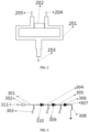
- the power divider 200 further includes a power divider transmission line 201 and an isolation resistor 202, where the power divider transmission line 201 is respectively connected to the first power divider port 205, the second power divider port 204 and the third power divider port 203.
- the isolation resistor 202 is arranged between a first segment line and a second segment line of the power divider transmission line 201, where the first segment line is arranged to be connected to the first power divider port 205, and the second segment line is arranged to be connected to the second power divider port 204.
- the power divider 200 shown in FIG. 2 is a Wilkinson power divider.
- the resonant unit 100 When receiving electromagnetic waves, the resonant unit 100 inputs two polarized incident signals through the first power divider port 205 and the second power divider port 204, and the signal combination is realized through the power divider 200.
- the phase shifter 300 when transmitting electromagnetic waves, the phase shifter 300 inputs the reflected signal through the third power divider port 203, and the power divider 200 distributes the reflected signal to the two polarization ports of the resonant unit, thus achieving the radiation of the two polarized signals.
- the power divider transmission line 201 may be a stripline structure as shown in FIG. 2 , which is respectively connected to the first power divider port 205, the second power divider port 204 and the third power divider port 203, and the isolation resistor 202 is arranged between the first segment line which is connected to the first power divider port 205 and the second segment line which is connected to the second power divider port 204, so that isolation of the two polarized signals is realized.
- the isolation resistor 202 may be a surface mount resistor, and a resistance value of the isolation resistor 202 may be adjusted according to actual requirements.
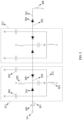
- the phase shifter 300 further includes a direct current (DC) blocking capacitor 302, a RF switch module and an alternating current (AC) blocking inductor 308 which are connected in series in sequence.
- the DC blocking capacitor 302 is connected to the phase shifter port 311.
- the phase shifter 300 includes a first phase shifter transmission line 301, a second phase shifter transmission line 304, a third phase shifter transmission line 305 and a fourth phase shifter transmission line 307.
- the RF switch module includes a first RF switch 310, a second RF switch 309 and a third RF switch 306.
- the DC blocking capacitor 302 is connected to the first RF switch 310 through the first phase shifter transmission line 301.
- the first RF switch 310 and the second RF switch 309 are connected in series through the second phase shifter transmission line 304.
- the second RF switch 309 and the third RF switch 306 are connected in series through the third phase shifter transmission line 305.
- the third RF switch 306 is connected to the AC blocking inductor 308 through the fourth phase shifter transmission line 307.
- the first phase shifter transmission line 301, the second phase shifter transmission line 304 and the third phase shifter transmission line 305 are respectively connected to a DC bias line 303.
- first phase shifter transmission line 301, the second phase shifter transmission line 304, the third phase shifter transmission line 305 and the fourth phase shifter transmission line 307 are connected in series through three RF switches to form a complete transmission line.
- the above transmission lines can adopt microstrip or stripline structures, and can be selected according to actual requirements.
- the DC blocking capacitor 302 can isolate direct current and prevent a bias current from entering the power divider 200.
- the AC blocking inductor 308 can isolate a RF signal and prevent the RF signal from entering the DC bias circuit 303.
- the DC blocking capacitor 302 and the AC blocking inductor 308 may be surface mount devices, and may be a distributed capacitor and a distributed inductor respectively. Types and parameters of the DC blocking capacitor 302 and the AC blocking inductor 308 may be selected according to actual requirements.
- the three RF switches in this embodiment may be PIN transistors, varactors, triodes, field effect transistors, single-pole-single-throw or single-pole-multi-throw switches, etc. In this embodiment, selections of RF switches are not limited.
- the three RF switches are connected through the first phase shifter transmission line 301, the second phase shifter transmission line 304 and the third phase shifter transmission line 305, so that series connections of the phase shifter transmission lines is realized, and four phases, i.e., 2-bit phase states, can be realized through different states of the three RF switches, therefore the phase quantization accuracy can be effectively improved and the scalability is good.
- the combined signal is input through the phase shifter port 311, passes through the DC blocking capacitor 302, and then enters the RF switch module. The combined signal passes through the RF switch which is turned on until the signal reaches an open circuit or short circuit terminal and is reflected.
- Different combinations of turn-on states of the three RF switches can realize four phase states, in which, when all the three RF switches are turned off, a combination state is "00", and a corresponding reflection phase is 0 degree; when the first RF switch 310 is turned on, the combination state is "01”, and the corresponding reflection phase is negative 90 degrees; when the first RF switch 310 and the second RF switch 309 are turned on, the combination state is "10”, and the corresponding reflection phase is negative 180 degrees; and when the first RF switch 310, the second RF switch 309 and the third RF switch 306 are turned on, the combination state is "11", and the corresponding reflection phase is negative 270 degrees.
- FIG. 6 shows a schematic diagram of reflection amplitudes obtained by using the metasurface unit of this embodiment.
- the four curves correspond to the combination states “00", “01”, “11” and “10” respectively from top to bottom.
- FIG. 7 shows a schematic diagram of reflection phases.
- the four curves correspond to the combination states “00", “01”, “10” and “11” from top to bottom.
- the reflection phases and the reflection amplitudes are different in different combination states, therefore the metasurface unit has strong expansibility and high phase quantization accuracy.
- the metasurface unit of this embodiment is similar to that of the embodiment one, except the following main differences.
- the phase shifter 300 includes a first phase shifter transmission line 301, a second phase shifter transmission line 304, a third phase shifter transmission line 305, a fourth phase shifter transmission line 307 and a fifth phase shifter transmission line 313.
- the RF switch module includes a third RF switch 306 and an RF switch group 312.
- the RF switch group 312 includes a first RF switch 310 and a second RF switch 309.
- the DC blocking capacitor 302 is connected to the first RF switch 310 through the first phase shifter transmission line 301.
- the first RF switch 310 and the second RF switch 309 are connected in parallel through the second phase shifter transmission line 304 and the fifth phase shifter transmission line 313.
- the second RF switch 309 and the third RF switch 306 are connected in series through the third phase shifter transmission line 305.
- the third RF switch 306 is connected to the AC blocking inductor 308 through the fourth phase shifter transmission line 307.
- the second phase shifter transmission line 304 and the fifth phase shifter transmission line 313 are connected in parallel, and a 2-bit phase response can also be achieved through different states of the three RF switches, with a difference that a configuration direction of the second RF switch 309 in this embodiment is different from that of the second RF switch 309 in the embodiment one, and two DC blocking capacitors 302 and a bias circuit 303 are adaptively arranged at the fifth phase shifter transmission line 313.
- a difference between this embodiment and the embodiment one is that a connection mode of the RF switches and the transmission lines is different, but the principle is basically the same, so the details are not repeated here.
- the metasurface unit of this embodiment is similar to that of the embodiment two, except the following main differences.
- the RF switch module includes at least two RF switch groups 312.
- the at least two RF switch groups 312 are connected in series with each other.
- a RF switch group 312 is added on the basis of the embodiment two, so that the phase shifter 300 can realize 8-bit phase states through five RF switches, further improving the accuracy of phase adjustment.
- the principle that the turn-on states of the five RF switches determine the reflection phase is similar to the principle of the embodiment two, except that one bit is added to describe the 8-bit phase states. For example, the combination state is "000" in a fully-turned-off state and "111" in a fully-turned-on state. For the sake of simplicity, the principle is not repeated here.
- a base station is also disclosed in the present disclosure.
- the base station includes the metasurface unit as described in any of the above embodiments.
- the embodiment of the present disclosure includes a resonant unit, where the resonant unit is configured to receive two polarized incident signals or radiate two polarized reflected signals; a power divider, which is connected to the resonant unit, where the power divider is configured to combine the two polarized incident signals input by the resonant unit into a combined signal, and/or divide a reflected signal input by a phase shifter into the two polarized reflected signals and output the two polarized reflected signals to the resonant unit; and the phase shifter, which is connected to the power divider, where the phase shifter is configured to perform phase modulation on the combined signal input by the power divider and output the reflected signal obtained by the phase modulation to the power divider.
- the combination and the division of the two polarized signals are realized through the power divider, so that the two polarized signals can share the same phase shifter, which effectively reduces the number of phase shifters in the metasurface unit and reduces the hardware cost.
Landscapes
- Engineering & Computer Science (AREA)
- Computer Networks & Wireless Communication (AREA)
- Physics & Mathematics (AREA)
- Electromagnetism (AREA)
- Variable-Direction Aerials And Aerial Arrays (AREA)
- Waveguide Aerials (AREA)
- Radar Systems Or Details Thereof (AREA)
- Aerials With Secondary Devices (AREA)
- Transmitters (AREA)
Applications Claiming Priority (2)
| Application Number | Priority Date | Filing Date | Title |
|---|---|---|---|
| CN202210275987.2A CN116826384B (zh) | 2022-03-21 | 2022-03-21 | 超表面单元及其基站 |
| PCT/CN2023/078163 WO2023179306A1 (fr) | 2022-03-21 | 2023-02-24 | Unité de métasurface et station de base associée |
Publications (2)
| Publication Number | Publication Date |
|---|---|
| EP4485694A1 true EP4485694A1 (fr) | 2025-01-01 |
| EP4485694A4 EP4485694A4 (fr) | 2025-06-25 |
Family
ID=88099854
Family Applications (1)
| Application Number | Title | Priority Date | Filing Date |
|---|---|---|---|
| EP23773557.6A Pending EP4485694A4 (fr) | 2022-03-21 | 2023-02-24 | Unité de métasurface et station de base associée |
Country Status (4)
| Country | Link |
|---|---|
| EP (1) | EP4485694A4 (fr) |
| JP (1) | JP7813380B2 (fr) |
| CN (1) | CN116826384B (fr) |
| WO (1) | WO2023179306A1 (fr) |
Families Citing this family (1)
| Publication number | Priority date | Publication date | Assignee | Title |
|---|---|---|---|---|
| CN120165246B (zh) * | 2025-03-21 | 2025-11-14 | 中国科学院苏州纳米技术与纳米仿生研究所 | 谐振敏感结构、全极化360°反射相位可调的编码超表面器件及其应用 |
Family Cites Families (20)
| Publication number | Priority date | Publication date | Assignee | Title |
|---|---|---|---|---|
| JP2569792B2 (ja) * | 1989-03-17 | 1997-01-08 | 三菱電機株式会社 | ビーム形成回路 |
| FR2812457B1 (fr) | 2000-07-28 | 2004-05-28 | Thomson Csf | Reflecteur hyperfrequence actif a bi-polarisation, notamment pour antenne a balalyage electronique |
| EP2555421B1 (fr) * | 2010-05-06 | 2018-01-10 | Huawei Technologies Co., Ltd. | Procédé, dispositif et système de polarisation de signal |
| FR2999021B1 (fr) * | 2012-12-05 | 2016-01-29 | Thales Sa | Focalisateur hyperfrequence et antenne a polarisation commandable associee |
| FR3010836B1 (fr) | 2013-09-18 | 2016-12-09 | Centre Nat Rech Scient | Dispositif de reflexion d'une onde, dispositif mobile, et systeme |
| CN105914465A (zh) * | 2016-04-15 | 2016-08-31 | 上海安费诺永亿通讯电子有限公司 | 圆极化天线及其无线通信设备 |
| US10490903B2 (en) * | 2016-10-18 | 2019-11-26 | Huawei Technologies Co., Ltd. | Liquid-crystal reconfigurable metasurface reflector antenna |
| JP2019050521A (ja) * | 2017-09-11 | 2019-03-28 | 株式会社東芝 | アンテナ装置、無線通信装置および信号送信方法 |
| TWI682585B (zh) | 2018-10-04 | 2020-01-11 | 和碩聯合科技股份有限公司 | 天線裝置 |
| JP7064467B2 (ja) * | 2019-04-18 | 2022-05-10 | 株式会社東芝 | アンテナ装置 |
| US11735833B2 (en) * | 2019-09-27 | 2023-08-22 | Apple Inc. | Transceiver circuit with polarization selection |
| CN111063994B (zh) * | 2019-12-06 | 2021-07-27 | 西安电子科技大学 | 基于超表面子阵列的基站天线及其电调方法 |
| CN110911845B (zh) * | 2019-12-06 | 2020-10-09 | 北京大学 | 一种宽带零交叉极化时空编码数字超表面单元及控制方法 |
| CN113764900B (zh) * | 2021-08-23 | 2022-07-01 | 西安电子科技大学 | 一种集成有太阳能电池的混合可重构智能反射表面 |
| CN113890578A (zh) * | 2021-09-29 | 2022-01-04 | 浙大城市学院 | 基于ris和相关信道无蜂窝系统功率设计方法 |
| CN113871861B (zh) * | 2021-09-29 | 2024-02-13 | 东南大学 | 一种4比特电子波束扫描平面天线阵列 |
| KR102374150B1 (ko) * | 2021-10-13 | 2022-03-11 | 국방과학연구소 | 능동형 메타표면을 이용한 배열 안테나 |
| CN113991312B (zh) * | 2021-10-26 | 2025-02-18 | 东南大学 | 双极化3bit相位独立可调的可重构智能超表面单元 |
| CN114188726B (zh) * | 2021-10-29 | 2024-04-26 | 电子科技大学长三角研究院(湖州) | 一种有源智能反射表面 |
| CN114188727A (zh) * | 2021-11-18 | 2022-03-15 | 中信科移动通信技术股份有限公司 | 阵列天线 |
-
2022
- 2022-03-21 CN CN202210275987.2A patent/CN116826384B/zh active Active
-
2023
- 2023-02-24 EP EP23773557.6A patent/EP4485694A4/fr active Pending
- 2023-02-24 WO PCT/CN2023/078163 patent/WO2023179306A1/fr not_active Ceased
- 2023-02-24 JP JP2024554211A patent/JP7813380B2/ja active Active
Also Published As
| Publication number | Publication date |
|---|---|
| CN116826384A (zh) | 2023-09-29 |
| JP2025507184A (ja) | 2025-03-13 |
| JP7813380B2 (ja) | 2026-02-12 |
| EP4485694A4 (fr) | 2025-06-25 |
| WO2023179306A1 (fr) | 2023-09-28 |
| CN116826384B (zh) | 2025-04-15 |
Similar Documents
| Publication | Publication Date | Title |
|---|---|---|
| US7907100B2 (en) | Phased array antenna with extended resonance power divider/phase shifter circuit | |
| US6549166B2 (en) | Four-port patch antenna | |
| US4737793A (en) | Radio frequency antenna with controllably variable dual orthogonal polarization | |
| CN113594704B (zh) | 宽带三极化可重构的高增益微带天线 | |
| CN112259962A (zh) | 基于双模平行波导的双频段共口径天线阵 | |
| US8773306B2 (en) | Communication system and method using an active phased array antenna | |
| CN115084873B (zh) | 一种基于电磁超材料的双极化1比特天线及数字比特阵列 | |
| US20210305708A1 (en) | Electrically-Controlled Switching Multi-Polarization Horn Antenna | |
| US11456764B2 (en) | Multi-function communication device with millimeter-wave range operation | |
| US12327924B2 (en) | Phase-shifting unit, antenna unit, phased array unit and phased array | |
| GB2238665A (en) | Microstrip antenna | |
| Fan et al. | Theory analysis and realization of single-/dual-port excitation in beam-forming network | |
| EP4485694A1 (fr) | Unité de métasurface et station de base associée | |
| US4751453A (en) | Dual phase shifter | |
| CN223023570U (zh) | 一种基于波导传输线的移相器 | |
| MXPA02008448A (es) | Dispositivo conmutador para aparatos para recibir y/o transmitir ondas electromagneticas. | |
| US20240186699A1 (en) | Switchable panel antennas with phase shifters | |
| Umar et al. | Antenna-duplexed passive beamforming front-end for joint communication and sensing | |
| CN113241506A (zh) | 腔体介质滑动式移相器及基站天线 | |
| Tadayon et al. | A Wide-Angle Scanning Phased Array Antenna with Non-Reciprocal Butler Matrix Beamforming Network | |
| CN118336380A (zh) | 双频双极化无源馈电网络 | |
| KR102388847B1 (ko) | 360도 위상 천이기 및 다기능 메타 안테나 장치 | |
| RU2719571C1 (ru) | Многофункциональный коммутатор для миллиметрового диапазона | |
| Senega et al. | A compact and wideband variable microwave phase shifter for phased arrays and diversity in S-band | |
| US20260066547A1 (en) | Antenna structure and communication device |
Legal Events
| Date | Code | Title | Description |
|---|---|---|---|
| STAA | Information on the status of an ep patent application or granted ep patent |
Free format text: STATUS: THE INTERNATIONAL PUBLICATION HAS BEEN MADE |
|
| PUAI | Public reference made under article 153(3) epc to a published international application that has entered the european phase |
Free format text: ORIGINAL CODE: 0009012 |
|
| STAA | Information on the status of an ep patent application or granted ep patent |
Free format text: STATUS: REQUEST FOR EXAMINATION WAS MADE |
|
| 17P | Request for examination filed |
Effective date: 20240927 |
|
| AK | Designated contracting states |
Kind code of ref document: A1 Designated state(s): AL AT BE BG CH CY CZ DE DK EE ES FI FR GB GR HR HU IE IS IT LI LT LU LV MC ME MK MT NL NO PL PT RO RS SE SI SK SM TR |
|
| A4 | Supplementary search report drawn up and despatched |
Effective date: 20250528 |
|
| DAV | Request for validation of the european patent (deleted) | ||
| DAX | Request for extension of the european patent (deleted) | ||
| RIC1 | Information provided on ipc code assigned before grant |
Ipc: H01P 1/18 20060101ALI20250522BHEP Ipc: H01Q 21/24 20060101ALI20250522BHEP Ipc: H01Q 1/24 20060101ALI20250522BHEP Ipc: H01Q 3/46 20060101ALI20250522BHEP Ipc: H01Q 15/00 20060101AFI20250522BHEP |