EP4485704A1 - Boîtier de connecteur enfichable encastré en matériau souple - Google Patents
Boîtier de connecteur enfichable encastré en matériau souple Download PDFInfo
- Publication number
- EP4485704A1 EP4485704A1 EP23181911.1A EP23181911A EP4485704A1 EP 4485704 A1 EP4485704 A1 EP 4485704A1 EP 23181911 A EP23181911 A EP 23181911A EP 4485704 A1 EP4485704 A1 EP 4485704A1
- Authority
- EP
- European Patent Office
- Prior art keywords
- contact element
- connector
- built
- housing
- flange
- Prior art date
- Legal status (The legal status is an assumption and is not a legal conclusion. Google has not performed a legal analysis and makes no representation as to the accuracy of the status listed.)
- Granted
Links
Images





Classifications
-
- H—ELECTRICITY
- H01—ELECTRIC ELEMENTS
- H01R—ELECTRICALLY-CONDUCTIVE CONNECTIONS; STRUCTURAL ASSOCIATIONS OF A PLURALITY OF MUTUALLY-INSULATED ELECTRICAL CONNECTING ELEMENTS; COUPLING DEVICES; CURRENT COLLECTORS
- H01R13/00—Details of coupling devices of the kinds covered by groups H01R12/70 or H01R24/00 - H01R33/00
- H01R13/46—Bases; Cases
- H01R13/514—Bases; Cases composed as a modular blocks or assembly, i.e. composed of co-operating parts provided with contact members or holding contact members between them
-
- H—ELECTRICITY
- H01—ELECTRIC ELEMENTS
- H01R—ELECTRICALLY-CONDUCTIVE CONNECTIONS; STRUCTURAL ASSOCIATIONS OF A PLURALITY OF MUTUALLY-INSULATED ELECTRICAL CONNECTING ELEMENTS; COUPLING DEVICES; CURRENT COLLECTORS
- H01R13/00—Details of coupling devices of the kinds covered by groups H01R12/70 or H01R24/00 - H01R33/00
- H01R13/46—Bases; Cases
- H01R13/52—Dustproof, splashproof, drip-proof, waterproof, or flameproof cases
- H01R13/521—Sealing between contact members and housing, e.g. sealing insert
-
- H—ELECTRICITY
- H01—ELECTRIC ELEMENTS
- H01R—ELECTRICALLY-CONDUCTIVE CONNECTIONS; STRUCTURAL ASSOCIATIONS OF A PLURALITY OF MUTUALLY-INSULATED ELECTRICAL CONNECTING ELEMENTS; COUPLING DEVICES; CURRENT COLLECTORS
- H01R13/00—Details of coupling devices of the kinds covered by groups H01R12/70 or H01R24/00 - H01R33/00
- H01R13/46—Bases; Cases
- H01R13/502—Bases; Cases composed of different pieces
- H01R13/5025—Bases; Cases composed of different pieces one or more pieces being of resilient material
-
- H—ELECTRICITY
- H01—ELECTRIC ELEMENTS
- H01R—ELECTRICALLY-CONDUCTIVE CONNECTIONS; STRUCTURAL ASSOCIATIONS OF A PLURALITY OF MUTUALLY-INSULATED ELECTRICAL CONNECTING ELEMENTS; COUPLING DEVICES; CURRENT COLLECTORS
- H01R13/00—Details of coupling devices of the kinds covered by groups H01R12/70 or H01R24/00 - H01R33/00
- H01R13/46—Bases; Cases
- H01R13/516—Means for holding or embracing insulating body, e.g. casing, hoods
-
- H—ELECTRICITY
- H01—ELECTRIC ELEMENTS
- H01R—ELECTRICALLY-CONDUCTIVE CONNECTIONS; STRUCTURAL ASSOCIATIONS OF A PLURALITY OF MUTUALLY-INSULATED ELECTRICAL CONNECTING ELEMENTS; COUPLING DEVICES; CURRENT COLLECTORS
- H01R13/00—Details of coupling devices of the kinds covered by groups H01R12/70 or H01R24/00 - H01R33/00
- H01R13/46—Bases; Cases
- H01R13/52—Dustproof, splashproof, drip-proof, waterproof, or flameproof cases
- H01R13/5202—Sealing means between parts of housing or between housing part and a wall, e.g. sealing rings
-
- H—ELECTRICITY
- H01—ELECTRIC ELEMENTS
- H01R—ELECTRICALLY-CONDUCTIVE CONNECTIONS; STRUCTURAL ASSOCIATIONS OF A PLURALITY OF MUTUALLY-INSULATED ELECTRICAL CONNECTING ELEMENTS; COUPLING DEVICES; CURRENT COLLECTORS
- H01R13/00—Details of coupling devices of the kinds covered by groups H01R12/70 or H01R24/00 - H01R33/00
- H01R13/46—Bases; Cases
- H01R13/52—Dustproof, splashproof, drip-proof, waterproof, or flameproof cases
- H01R13/5213—Covers
-
- H—ELECTRICITY
- H01—ELECTRIC ELEMENTS
- H01R—ELECTRICALLY-CONDUCTIVE CONNECTIONS; STRUCTURAL ASSOCIATIONS OF A PLURALITY OF MUTUALLY-INSULATED ELECTRICAL CONNECTING ELEMENTS; COUPLING DEVICES; CURRENT COLLECTORS
- H01R13/00—Details of coupling devices of the kinds covered by groups H01R12/70 or H01R24/00 - H01R33/00
- H01R13/46—Bases; Cases
- H01R13/52—Dustproof, splashproof, drip-proof, waterproof, or flameproof cases
- H01R13/5216—Dustproof, splashproof, drip-proof, waterproof, or flameproof cases characterised by the sealing material, e.g. gels or resins
-
- H—ELECTRICITY
- H01—ELECTRIC ELEMENTS
- H01R—ELECTRICALLY-CONDUCTIVE CONNECTIONS; STRUCTURAL ASSOCIATIONS OF A PLURALITY OF MUTUALLY-INSULATED ELECTRICAL CONNECTING ELEMENTS; COUPLING DEVICES; CURRENT COLLECTORS
- H01R13/00—Details of coupling devices of the kinds covered by groups H01R12/70 or H01R24/00 - H01R33/00
- H01R13/73—Means for mounting coupling parts to apparatus or structures, e.g. to a wall
- H01R13/74—Means for mounting coupling parts in openings of a panel
-
- H—ELECTRICITY
- H01—ELECTRIC ELEMENTS
- H01R—ELECTRICALLY-CONDUCTIVE CONNECTIONS; STRUCTURAL ASSOCIATIONS OF A PLURALITY OF MUTUALLY-INSULATED ELECTRICAL CONNECTING ELEMENTS; COUPLING DEVICES; CURRENT COLLECTORS
- H01R13/00—Details of coupling devices of the kinds covered by groups H01R12/70 or H01R24/00 - H01R33/00
- H01R13/44—Means for preventing access to live contacts
- H01R13/447—Shutter or cover plate
-
- H—ELECTRICITY
- H01—ELECTRIC ELEMENTS
- H01R—ELECTRICALLY-CONDUCTIVE CONNECTIONS; STRUCTURAL ASSOCIATIONS OF A PLURALITY OF MUTUALLY-INSULATED ELECTRICAL CONNECTING ELEMENTS; COUPLING DEVICES; CURRENT COLLECTORS
- H01R13/00—Details of coupling devices of the kinds covered by groups H01R12/70 or H01R24/00 - H01R33/00
- H01R13/46—Bases; Cases
- H01R13/52—Dustproof, splashproof, drip-proof, waterproof, or flameproof cases
- H01R13/5219—Sealing means between coupling parts, e.g. interfacial seal
Definitions
- the present invention relates to a built-in connector, wherein the built-in connector is provided for establishing a plug connection, in particular a mechanically lockable one, with a cable connector that is matched to the built-in connector as a counterpart and can be inserted into an opening of the built-in connector.
- the contact pins are inserted into a contact carrier, whereby this contact carrier, in addition to receiving and aligning the contact pins, also has the function of providing the interior into which the cable connector is inserted to make contact with the contact pins. This interior can also have elements for locking the cable connector.
- the contact carrier provides a connecting flange, through whose mounting holes screws can be guided for screwing the built-in connector onto a mounting plate.
- the contact carrier is inserted into a built-in connector housing, with parts of the contact pins being pushed out of the built-in connector housing through openings specially provided for this purpose. These parts of the contact pins protruding from the housing are then connected, for example via terminals specially provided for this purpose, to strands of a cable, for example a power cable, which provides the signal intended for transmission via the plug connection of the built-in and cable connectors, for example a power supply signal.
- a cable for example a power cable
- the panel connector housing is made of a hard, inelastic material (e.g. a harder thermoplastic), whereby this harder housing does not fit as tightly to the contact pins pushed out through the openings in the housing. Consequently, these press fits between the prior art panel connector housing and the corresponding contact pins are leaky/permeable to dust, water and/or air.
- a hard, inelastic material e.g. a harder thermoplastic
- Such a leak between the housing and the contact pin is a problem, especially when the built-in connector is used outdoors (e.g. loudspeakers at open-air festivals). Rainfall can occur at any time, for example, and moisture can penetrate the built-in connector if no cable connector is plugged in and the sealing cap intended for temporarily closing and sealing the interior of the built-in connector has not been put in place. The moisture that has penetrated can then run down to the press fit between the built-in connector housing and the contact pin and collect there.
- this press fit is not tight, particularly against water, due to the harder housing material, so with built-in connectors of the state of the art there is a risk that the moisture will penetrate further into the device and cause a short circuit, which can damage the device and, in the worst case, injure bystanders.
- a further object is to provide a built-in connector and a built-in connector housing in which the creation of a seal against dust, air and/or water is simplified, thereby enabling outdoor use, reducing the risk of short circuits and/or fulfilling certain standards without additional work.
- the housing pot is made of a material with a Shore A hardness in the range from 65 to 95, in particular in the range from 75 to 95.
- Shore A hardness in the range from 65 to 95, in particular in the range from 75 to 95.
- the material consists at least predominantly of a plastic.
- the material of the housing pot can consist of at least 60%, in particular at least 80%, of plastic, with additives such as plasticizers or fire retardants mixed into the plastic.
- plasticizers or fire retardants mixed into the plastic.
- the material of the housing pot is flame retardant, which can be achieved, for example, by adding fire retardants to the material of the housing pot.
- the axial direction of the central axis of the housing pot is the direction in which the central axis runs from the plug-in end of the housing (top surface) to the housing bottom (base surface). This direction also corresponds, among other things, to the insertion direction of the contact element carrier into the housing pot and the insertion direction of the cable connector into the contact element carrier (or the insertion direction of the cable connector into the built-in connector).
- the at least one contact element is accommodated by the contact element carrier in such a way, for example, that a first partial area of the contact element is inserted into the contact element carrier and is fixed there, for example, by hooking, clamping or gluing, while a second partial area of the contact element protrudes from the end piece of the contact element carrier, which is inserted into the housing pot through the insertion opening. Since the contact element carrier is inserted so far into the housing pot that this end piece hits the housing base, the second partial area of the contact element protruding from the end piece slides out of the housing pot through the ejection opening. Consequently, it can also be said that the at least one contact element is at least partially accommodated by the contact element carrier and thus at least partially fixed within the built-in connector.
- the inventive design of the built-in connector with a housing pot made of a softer, more elastic material than in built-in connectors of the prior art has the advantage that the housing pot and the at least one extension opening can be manufactured with such dimensions that, on the one hand, the housing pot fits snugly against the contact element carrier when it is pushed in, which is made of a harder plastic (e.g. a harder thermoplastic), and, on the other hand, the at least one extension opening fits snugly against the contact element that is passed through.
- the extension opening has a slightly smaller area than the cross-sectional area of the part of the contact element that is pushed out of the housing pot through the extension opening, so that the extension opening expands when the contact element is pushed out, for which a certain force must be applied.
- the housing pot of the built-in connector according to the invention is made of a softer, more elastic material (e.g. comparable to rubber), it can expand more easily and can also fit better to the contact element. In this way, press fits between the soft, elastic housing pot and the harder, less elastic contact element are impermeable to dust, water and/or air, which means that the entire built-in connector is dust, water and airtight when installed, even if, for example, it was forgotten to put the sealing cap over the insertion opening of the built-in connector during rain, and water could therefore get into the built-in connector.
- the built-in connector having the housing pot according to the invention is able to meet the IP65 or IP67 standards even when the sealing cap is not in place or the cable connector is plugged in, without the need to use additional components/sealing materials (such as a liquid sealant that hardens after application). Consequently, the built-in connector according to the invention can save additional costs (e.g. material procurement costs, additional machines/employees) and additional workload due to, for example, additional work steps. These additional costs/work steps are therefore not incurred with the built-in connector according to the invention, since the water-tight or air-tight press fits mean that no further sealing is necessary, which is why the disadvantages of the prior art are overcome.
- additional costs e.g. material procurement costs, additional machines/employees
- thermoplastic or a thermoplastic elastomer
- the housing pot can be manufactured by injection molding, pressing or vulcanization and that the housing has an insulating effect against electrical current.
- the three ejection openings in the housing base are particularly sensitive points on the housing pot, where leaks often occur.
- built-in connector housings from the prior art which, as already described, are generally made of a harder material, in particular predominantly of a harder thermoplastic (or thermoplastic elastomer)
- attempts are made to seal the contact area between the edge of the ejection opening and the contact element pushed through this opening by designing the ejection opening with a smaller area than the cross-sectional area of the contact element. In this way, the contact element presses on the edge of the ejection opening and turns it outwards.
- the edge of the ejection opening that has been turned outwards is then provided with a sealing paste, for example.
- a slight overpressure within the built-in connector is sufficient to push open the edge area of the ejection opening that is turned outwards, thus causing the built-in connector to leak again.
- Such overpressure can be triggered by temperature fluctuations within the device, for example by the device heating up quickly in direct sunlight.
- the aforementioned exemplary embodiment of the built-in connector solves this problem in that the geometric shape of the extension opening is adapted to the shape of the cross-sectional area of the contact element.
- the extension opening is also rectangular.
- the area of the extension opening is, for example, only slightly smaller than the cross-sectional area of the contact element, as a result of which the edge of the extension opening does not turn outwards when the contact element is pushed through. In this way, the press fit of the contact element in the extension opening rests against the contact element over the entire area within the extension opening and is not pressed open by excess pressure within the built-in connector.
- the at least one ejection opening has a largely rectangular shape, wherein in this largely rectangular shape the two longer sides of the rectangle are designed as bulges/curvatures directed towards a rectangle center, in particular wherein the at least one ejection opening thus has at least largely a shape similar to a biconcave lens.
- the flange-like projection has a rectangular shape, in particular with rounded corners, wherein the radially protruding connecting strip is formed on a, in particular rounded, corner of the flange-like projection, in particular wherein the radially protruding connecting strip is formed on the, in particular rounded, corner of the flange-like projection in such a way that an angle in the range of 120 degrees to 140 degrees, in particular 135 degrees, is formed between a longer side of the two sides of the flange-like projection forming said, in particular rounded, corner.
- connecting strip has the disadvantage that when several built-in connectors are arranged vertically next to one another, which is quite common in loudspeaker boxes, for example, the connecting strip and the sealing plug protrude over the insertion opening of the built-in connector arranged directly above or below it, thus hindering the insertion process of this built-in connector.
- the exemplary embodiment of the invention described above has the advantage that, due to the arrangement at a corner of the flange-like projection of the housing and the alignment of the connecting strip, for example along a diagonal of the flange-like projection, the connecting strip and the sealing plug protrude past the built-in connector above or below in a vertical arrangement of several built-in connectors next to one another and thus the insertion process is not disrupted.
- the connecting strip is in particular aligned diagonally upwards (and not diagonally downwards), since in this way no rainwater can collect in the sealing plug.
- the respective connecting strip can be arranged in particular at the corner facing the middle of the 2x2 arrangement, whereby all four connecting strips and sealing plugs protrude into this middle.
- several built-in connectors provided with the housing pot according to the invention can be arranged in a very small space without having to accept the disadvantages of the prior art.
- the flange-like projection has two, in particular in diagonally opposite rounded corners of the flange-like projection, recesses for the passage of fastening means, intended to fasten the built-in connector to the mounting plate, wherein the two recesses are positioned coaxially to mounting holes, in particular arranged in diagonally opposite rounded corners of the connecting flange, in particular wherein a respective diameter of the two recesses corresponds to a respective diameter of the mounting holes.
- the two diagonally opposite rounded corners of the flange-like projection in each of which one of the two recesses for the passage of fastening means is arranged, each have a smaller radial extension than the two diagonally opposite rounded corners of the connecting flange, in each of which one of the two mounting holes is arranged.
- the housing pot of the built-in connector according to the invention has, in some special embodiments, a flange-like projection, which when screwing the connecting flange to the mounting plate is pressed against both the connecting flange and the mounting plate and thus functions, among other things, as a seal between these two parts.
- the flange-like projection is made of the soft, rubber-like material just like the housing pot, the flange-like projection is strongly compressed, particularly in the areas around the screw feedthroughs.
- the flange-like projection from swelling out sideways under the connecting flange at these strongly compressed points is prevented by the fact that the flange-like projection has a smaller extension in these areas than the connecting flange.
- the first and second sealing lips each serve to form a corresponding press fit that seals even with a low contact pressure.
- the housing casing in the area of the housing base is pushed slightly to the side in the case of built-in connectors according to the state of the art (because the housing casing is curved inwards, for example, in order to rest against the contact element carrier), which increases the tension within the housing base.
- This increase in tension can result in the press fit between the ejection opening arranged near the housing casing and a contact element located in this opening becoming distorted and thus becoming leaky.
- this problem is also solved by additionally sealing the contact point between the ejection opening and the contact element using sealing agents such as adhesives, sealing pastes or O-rings.
- three ejection openings extend within the housing base.
- the, in particular cylindrical, housing shell and the contact element carrier each have such a radial extension that a press fit between the, in particular cylindrical, housing shell and the at least partially contact element carrier inserted through the insertion opening into the housing pot.
- the integrally formed parts of the housing pot are made of the material with the Shore A hardness in the range of 60 to 100, in particular wherein the integrally formed parts of the housing pot are manufactured by means of injection molding, pressing or vulcanization.
- the injection molding process enables simple production of the respective parts of the housing pot and, in particular, simple production of the one-piece housing pot from these parts.
- the material used can first be melted and then injected into the corresponding mold.
- the material must be able to solidify in the corresponding mold by cooling and maintain this solidified shape until it is heated again.
- the soft material it is therefore particularly advantageous for the soft material to be a thermoplastic or to consist predominantly of this thermoplastic (or thermoplastic elastomer) (additives such as plasticizers or fire retardants are often added), since many of the thermoplastics have the properties described above and can therefore be used for the injection molding process.
- thermoplastics have a Shore hardness, especially amorphous thermoplastics such as low-density polyethylene (LD-PE), atactic polypropylene (PP-at) or atactic polystyrene (PS-at), which is quite close to the Shore hardness of the soft material of the housing pot.
- LD-PE low-density polyethylene
- PP-at atactic polypropylene
- PS-at atactic polystyrene
- a further advantage of an embodiment of the housing pot according to the invention compared to the prior art is that the housing pot has the aforementioned Shore A hardness despite the addition of a flame retardant.
- the production of such a flame-retardant V0 material in this Shore A hardness range is a great challenge, since materials that have been provided with such a flame retardant have so far been very become hard and brittle and thus lose their sealing effect.
- Flame protection is particularly important for the powerCON type built-in plugs, as these plugs must meet the UL 94 standard (ie the material and plug must be certified V0 according to UL94 at 1mm). Due to the standards and requirements of these standards, it is advantageous that flame protection (a certain proportion of a flame-retardant additive) is added to this material.
- the protection category can be determined by the percentage of the flame-retardant additive that is added to the overall mixture.
- the material of the housing pot can also be UV-stabilized (according to UN standard UL50E, and therefore requires a UL certificate f1).
- UV stabilizers of 10-15 wt.% (percent by weight) or 10-15 mol-% (mole percent) or 10-15 vol.% (percent by volume) are mixed into the material. Due to the UV stabilization, the built-in connector according to the invention or the housing pot according to the invention can be used outdoors.
- TOP Truste Outdoor Protection
- the soft material of the housing pot according to the invention is furthermore designed in such a way that so-called undercuts can also be realized during the production of the housing by means of an injection molding process, which enables, for example, the design of the first sealing lip or the wall-like elevation.
- the contact element carrier is made of a material with a Shore D hardness in the range of 60 to 100.
- the term contact element carrier does not only refer to a pure contact element holder understood.
- the contact element carrier also has the task of providing the socket for receiving the cable plug as well as elements for locking the cable plug in this socket.
- the contact element carrier provides the connecting flange, through whose mounting holes screws are passed for screwing the contact element carrier to the mounting plate (e.g. a loudspeaker box). The connecting flange is pressed against the mounting plate and thus prevents the contact element carrier or the entire built-in connector from slipping through the recess in the mounting plate.
- the housing is often put over the contact element carrier without itself having a flange-like projection, which can also press on the mounting plate or be screwed onto it.
- the contact element carrier also serves as a type of skeleton or support structure which accommodates the other parts of the built-in connector or is surrounded by them, as a supporting and shaping structure, for example, spans the built-in connector interior intended for receiving and locking the cable connector and enables the built-in connector to be fixed to the mounting plate.
- the contact element carrier is intended to form the support structure/skeleton of the built-in connector, it is particularly advantageous if the contact element carrier is made of a harder material than the housing pot. Since the contact element carrier in an advantageous embodiment is manufactured just like the housing pot by means of injection molding, pressing or vulcanization, it is particularly advantageous if the material of the contact element carrier comprises a thermoplastic, in particular consists predominantly of this thermoplastic. Since the contact element carrier in this exemplary embodiment has a Shore hardness in a certain range, it is particularly advantageous to use a thermoplastic for the material of the contact element carrier that has a similar Shore hardness. For this purpose, semi-crystalline thermoplastics such as For example, isotactic PP, isotactic PS or high-density polyethylene (HD-PE) may be considered.
- semi-crystalline thermoplastics such as For example, isotactic PP, isotactic PS or high-density polyethylene (HD-PE) may be considered.
- the retaining element is arranged and designed such that the retaining element counterpart engages behind the retaining element after actuation of the first part of the locking mechanism.
- the retaining element is arranged and provided with an oblique course such that by and upon actuation of the first part of the locking mechanism, the retaining element counterpart is moved along the oblique course until the retaining element counterpart encounters a rotary stop and thus a final insertion position of the cable connector contact element carrier interior (and thus also in the built-in connector) is reached.
- the contact element carrier interior has mechanical key counterparts which are provided to interact with coordinated key elements of the cable connector in such a way that the cable connector can be inserted into the built-in connector in only one specific rotational orientation predetermined by the key counterparts.
- the invention also relates to a housing pot (or a built-in connector housing) for a built-in connector according to one of the previously described embodiments (or according to one of claims 1 to 14).
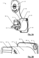
- Figure 1A shows a perspective view of an exemplary embodiment of the housing pot 1 according to the invention, in which the cylindrical housing shell 4, the circular housing base 10, the predominantly rectangular flange-like projection 14, the connecting strip 16, the pot-shaped sealing plug 17, the grip tab 18 and the separating element 19 are formed in one piece.
- the insertion opening 6 extends in the insertion-side end 5 of the housing 1, at which the flange-like projection 14 extends radially.
- the housing base 10 has three ejection openings 11 in this embodiment of the housing 1.
- FIG 1B the elevation 20 is shown, which is designed to be inserted into a corresponding recess in the connecting flange 15 and to be held in this recess with a press fit, whereby the housing 1 and the contact element carrier 7 are held firmly together. Furthermore, the first sealing lip 23 is shown, which is intended to seal the contact area of the flange-like projection 14 with the connecting flange 15.
- FIGS. 2A and 2B show a perspective view of an exemplary embodiment of the housing pot 1 according to the invention, wherein this exemplary embodiment of the housing pot 1 according to the invention further comprises the second sealing lip 24.
- This second sealing lip 24 is provided to seal the flange-like projection 14 in the edge region and the recess 21 and thus seal the contact area of the flange-like projection 14 with the mounting plate.
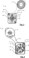
- Figure 3 shows a front view of an exemplary embodiment of the built-in connector 2 according to the invention, which illustrates the mounting holes 25, the retaining elements 26 designed as grooves, the mechanical locking element 27 provided for the latch of the latch slide on the cable connector side and the insertion opening 8 provided for inserting the cable connector into the built-in connector.
- Figure 4 shows a rear view of an exemplary embodiment of the built-in connector 2 according to the invention, which illustrates the separating element 19 designed as a trident star. Furthermore, the arrangement of the connecting strip 16 in a rounded corner of the housing 1 can be seen, wherein the connecting strip is arranged obliquely (along a diagonal from one corner to the other corner of the housing) such that an angle of approximately 135 degrees is formed between one side of the flange-like projection 14 and the connecting strip 16.
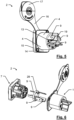
- Figure 5 shows a perspective view of an exemplary embodiment of the built-in connector 2 according to the invention
- Figure 6 the corresponding perspective view of an exploded view of an exemplary embodiment of the built-in connector 2 according to the invention.
- the sealing ring 28 is arranged within the contact element carrier 7 and serves as an additional seal in case one of the previously described press fits 1 should become leaky due to, for example, material fatigue/material aging.
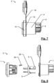
- Figure 7 shows a side view of an exemplary embodiment of the built-in connector 2 according to the invention and Figure 8 shows a side view of an exploded view of an exemplary embodiment of the built-in connector 2 according to the invention. These two figures serve to further illustrate the inventive built-in connector 2.
- the element 29 serves as an additional fixation of the contact element carrier 7 in the housing 1.
- Figure 9A shows a schematic representation of the housing interior before and Figure 9B after inserting the contact element carrier and passing a contact element through the ejection opening in built-in connectors according to the state of the art.
- the ejection opening is designed with a smaller area than the cross-sectional area of the contact element in order to ensure that the edge of the ejection opening bulges out when the contact element is passed through.
- the ejected area is pressed against the contact element, although the press fit is not formed over the entire thickness of the housing base.
- the ejection opening is designed in a funnel shape. As already described, with such a design, however, a slight excess pressure within the built-in connector is sufficient to press open the edge area of the ejection opening that has been pushed outwards and thus ensure that the built-in plug is leaking again.
- Figure 9B illustrates how the housing shell, which is curved into the housing interior in the area of the housing base, forms a type of step onto which a force acts when the contact element carrier or a sealing agent, such as an O-ring, is pushed in and pressed onto the housing base (here indicated by the arrows), whereby the housing shell is pushed (slightly) to the side in the area of the housing base.
- a force acts when the contact element carrier or a sealing agent, such as an O-ring, is pushed in and pressed onto the housing base (here indicated by the arrows), whereby the housing shell is pushed (slightly) to the side in the area of the housing base.
- a sealing agent such as an O-ring
- Figure 11A shows a schematic representation of the housing interior 12, in particular the ejection opening 11 and the wall-like elevation 30, before and Figure 11B after the insertion of the contact element carrier 7 and the passage of a contact element 9 through the ejection opening 11 in the built-in connector 2 according to the invention.
- the contact element 9 can be very easily guided through the ejection opening 11 even without a funnel-shaped design. Because the geometric shape and the surface of the ejection opening 11 are adapted to the cross-sectional area of the contact element 9, it is possible with the housing pot 1 according to the invention to push the contact element 9 through the ejection opening 11 without its edge or inner surface (also referred to as the surface extending into the ejection opening 11) turning outwards/bulging.
- the housing base 10 is much more likely to be pushed slightly to the side by the contact element 9 (which is easily possible with the elastic material of the housing 1 without a major increase in tension in the housing base 10), whereby the inner surface of the opening 11 may be stretched slightly, but continues to lie fully against the contact element 9. In other words, the press fit of the contact element 9 in the ejection opening 11 rests against the contact element 9 over the entire area within the ejection opening (inner surface).
- the area of the ejection opening 11 was selected such that the inner surface of the opening 11 is stretched when the contact element 9 is pushed through. In this way, elevations are formed on both the inside and the outside 13 of the housing base 10, which are in contact with the contact element 9 and which prevent the housing base 10 from being pushed outwards or inwards at the contact point with the contact element 9 in the event of overpressure or underpressure inside the built-in connector 2 and in the event of overpressure or underpressure outside the built-in connector 2.
- FIGs 11A and 11B further illustrate that in the case of the built-in connector 2 according to the invention, the wall-like elevation 30 is arranged free-standing and without contact with the housing shell 4 in the housing interior 12, in particular on the housing base 10. If then, as in Figure 11B shown, the contact element carrier 7 is pushed in as far as the housing base 10, the wall-like elevation 30 is pushed (slightly) to the side by the contact element carrier 7, whereby the second press fit is formed between the wall-like elevation 30 and the contact element carrier 7.
- the wall-like elevation 30 has a third sealing lip (extending orthogonally to the central axis of the housing pot 1 from the wall-like elevation 30 towards the central axis of the housing pot 1), which rests against the pushed-in contact element carrier 7 in such a way that the first press fit is formed between the third sealing lip and the contact element carrier 7.
- the wall-like elevation 30 is attached to the housing base 10 in a free-standing manner and without contact with the housing shell 4, it can be pushed to the side by the inserted contact element carrier 7 without the housing shell 4 being pushed outwards in the area of the housing base and thus increasing the tension within the housing base 10.
- the ejection opening 11 arranged near the housing shell 4 is prevented from warping and the press fit between the inner surface of the ejection opening 11 and a contact element 9 passing through it becomes leaky. Consequently, subsequent sealing of the contact point between the inner surface of the ejection opening 11 and the contact element 9 passing through it by means of an additional sealing agent such as an O-ring or an adhesive that is initially liquid and hardens over time is not necessary in the housing pot 1 according to the invention or the built-in connector 2 according to the invention compared to the previously known solutions from the prior art.
- an additional sealing agent such as an O-ring or an adhesive that is initially liquid and hardens over time
- Figure 12 shows a schematic representation of the arrangement of connecting flange 15, flange-like projection 14 and a mounting plate 31 in the built-in connector 2 according to the invention.
- the flange-like projection 14 has a raised portion 20 directed opposite to the axial direction of the central axis, wherein the raised portion 20 of the flange-like projection 14 is inserted into a matching recess 32 of the connecting flange 15 of the contact element carrier 7 in such a way that a press fit is formed between the raised portion 20 and the matching recess 32. It is also clear that the flange-like projection 14 has the same radial extent as the connecting flange 15, so that the flange-like projection 14 applied to the connecting flange 15 is flush with the connecting flange 15.
- the built-in connector 2 is inserted into a recess in the installation plate 31, on the one hand the housing shell 4 rests on an inner surface of this recess and on the other hand the flange-like projection 14, in particular the second sealing lip 24 arranged on the side of the flange-like projection 14 directed in the axial direction, rests on the front of the installation plate 31.
- the front of the installation plate 31 is directed from where the cable connector can be guided to the built-in connector 2 - which is in the state mounted on the installation plate 31.
- the connecting flange 15 By screwing the connecting flange 15 onto the mounting plate 31, whereby the connecting flange 15 does not touch the mounting plate 31 in this embodiment, the flange-like projection 14 in between, in particular the second sealing lip 24, of the housing 1 is pressed onto the mounting plate 31, whereby this contact point between the built-in connector 2 and the mounting plate 31 becomes impermeable to dust, moisture and/or air.
- the contact point between the built-in connector 2 and the mounting plate 31 is already sealed against dust, water and/or air even without the use of additional sealing means.
- the housing pots of the housing pot pair 41 and the contact element carriers of the contact element carrier pair 47 are each designed essentially as described above, but one housing pot-contact element carrier combination is designed to provide a signal input plug-in opening 8A and the other housing pot-contact element carrier combination is designed to provide a signal output plug-in opening 8B.
- the flange element provided by the housing pot pair 41 and the contact element carrier pair 47 has fastening provisions 25, e.g. in the form of holes for receiving fastening means for fastening the built-in connector to a mounting plate.
- the built-in connector 42 further comprises connecting elements 50 which connect the contact elements 9 for the signal input plug opening 8A and the signal output plug opening 8B to one another in such a way that the contact elements of the signal input plug opening 8A and the signal output plug opening 8B are led to a common connection element 51.
- the contact elements 9, housing pots of the housing pot pair 41 and the contact element carriers of the contact element carrier pair 47 are each designed in such a way that they are analogous to the Figures 1 to 6 described embodiments of the built-in connector.
- a cover plate 53 covers the exposed conductive elements for connecting the contact elements 9 of the signal input plug opening 8A and the Signal output plug opening 8B.
- the element 29 serves as an additional fixation of the contact element carrier pair 47 in the housing 1.
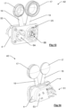
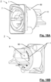
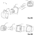
- Figure 18A and Figure 18B show perspective views and Figures 19A and 19B show corresponding perspective views in exploded representation of an exemplary embodiment of the built-in connector 2 according to the invention, wherein the built-in connector 2 has a support flange 60 for rear fastening to a mounting plate.
- the support flange 60 has a passage adapted to the diameter of the housing shell 4, through which the housing pot 1 is passed in such a way that, on the one hand, the flange-like projection of the housing pot 1 comes to rest on the support flange 60 (congruently), in particular wherein the radial extent of the flange-like projection and the support flange 60 is the same, and, on the other hand, the housing base and the correspondingly passed through contact elements 9 leave the passage of the support flange 60 again.
- the support flange 60 has a recess on the insertion side, into which a correspondingly designed counterpart, directed to the rear (in a direction away from the mounting plate), is inserted with precision and the two parts are thus connected to one another, e.g. by means of a press fit.
- the support flange 60 also has at least one blind hole for receiving a fastening means (e.g. screw) coming from a mounting plate for fastening the built-in connector 2 to the mounting plate.
- the flange-like projection has at least one recess provided for the passage of the fastening means, which coincides with the opening of the blind hole when the housing pot 1 and the support flange 60 are properly plugged together.
- the contact element carrier 7 of the built-in connector 2 has a connecting flange which has a smaller radial extension than in other embodiments.
- This reduced connecting flange is inserted into a corresponding recess in the flange-like projection of the housing pot 1, which is designed as a counterpart, in such a way that the plug-in end of the contact element carrier 7 merges flush with the plug-in end of the housing pot 1 and thus the plug-in end of the built-in connector 2 forms a flat surface in the area of the contact element carrier 7 accommodated in the housing pot 1.
- this flat surface is designed to be placed on the back of a mounting plate, wherein a corresponding fastening means (e.g. screw) is passed through the mounting plate and the at least one recess of the flange-like projection and then engages in the at least one blind hole.
- a fastening means e.g. screw
- the fastening means is not guided directly through the installation plate for fixing the built-in connector 2 to the rear side of the installation plate, but a second support flange is first screwed to the front side of the installation plate by means of the fastening means.
Landscapes
- Chemical & Material Sciences (AREA)
- Dispersion Chemistry (AREA)
- Connector Housings Or Holding Contact Members (AREA)
Priority Applications (7)
| Application Number | Priority Date | Filing Date | Title |
|---|---|---|---|
| EP23181911.1A EP4485704B1 (fr) | 2023-06-27 | 2023-06-27 | Boîtier de connecteur enfichable encastré en matériau souple |
| CN202311266800.3A CN119209066A (zh) | 2023-06-27 | 2023-09-27 | 内置插入式连接器及壳体罐 |
| CN202322650946.XU CN221201578U (zh) | 2023-06-27 | 2023-09-27 | 内置插入式连接器及壳体罐 |
| EP23207725.5A EP4485705B1 (fr) | 2023-06-27 | 2023-11-03 | Connecteur encastrable avec système de réception avec boitier en matière molle |
| US18/520,888 US20250007200A1 (en) | 2023-06-27 | 2023-11-28 | Built-in plug-in connector housing made from soft material |
| US18/739,873 US20250007202A1 (en) | 2023-06-27 | 2024-06-11 | Receptacle system with a housing pot made from soft material |
| CN202410848950.3A CN119209082A (zh) | 2023-06-27 | 2024-06-27 | 带有由软材料制成的外壳筒的插座系统 |
Applications Claiming Priority (1)
| Application Number | Priority Date | Filing Date | Title |
|---|---|---|---|
| EP23181911.1A EP4485704B1 (fr) | 2023-06-27 | 2023-06-27 | Boîtier de connecteur enfichable encastré en matériau souple |
Publications (2)
| Publication Number | Publication Date |
|---|---|
| EP4485704A1 true EP4485704A1 (fr) | 2025-01-01 |
| EP4485704B1 EP4485704B1 (fr) | 2025-08-06 |
Family
ID=87003359
Family Applications (2)
| Application Number | Title | Priority Date | Filing Date |
|---|---|---|---|
| EP23181911.1A Active EP4485704B1 (fr) | 2023-06-27 | 2023-06-27 | Boîtier de connecteur enfichable encastré en matériau souple |
| EP23207725.5A Active EP4485705B1 (fr) | 2023-06-27 | 2023-11-03 | Connecteur encastrable avec système de réception avec boitier en matière molle |
Family Applications After (1)
| Application Number | Title | Priority Date | Filing Date |
|---|---|---|---|
| EP23207725.5A Active EP4485705B1 (fr) | 2023-06-27 | 2023-11-03 | Connecteur encastrable avec système de réception avec boitier en matière molle |
Country Status (3)
| Country | Link |
|---|---|
| US (2) | US20250007200A1 (fr) |
| EP (2) | EP4485704B1 (fr) |
| CN (3) | CN119209066A (fr) |
Families Citing this family (1)
| Publication number | Priority date | Publication date | Assignee | Title |
|---|---|---|---|---|
| USD1042358S1 (en) * | 2021-06-18 | 2024-09-17 | Tyco Electronics (Shanghai) Co., Ltd. | Connector housing |
Citations (4)
| Publication number | Priority date | Publication date | Assignee | Title |
|---|---|---|---|---|
| CH375055A (fr) * | 1962-04-28 | 1964-02-15 | Baillod Frederic | Dispositif de raccordement pour cordons électriques |
| WO2020144005A1 (fr) * | 2019-01-11 | 2020-07-16 | Phoenix Contact E-Mobility Gmbh | Pièce de connecteur enfichable pourvue d'une pièce de connecteur à relier à une pièce de boîtier |
| WO2021058131A1 (fr) * | 2019-09-24 | 2021-04-01 | Neutrik Ag | Connecteur électrique |
| CN218548966U (zh) * | 2022-06-02 | 2023-02-28 | 纽陲客股份公司 | 嵌入式插式连接器 |
Family Cites Families (1)
| Publication number | Priority date | Publication date | Assignee | Title |
|---|---|---|---|---|
| JPH073581Y2 (ja) * | 1990-04-24 | 1995-01-30 | 矢崎総業株式会社 | コネクタとグロメットの取付構造 |
-
2023
- 2023-06-27 EP EP23181911.1A patent/EP4485704B1/fr active Active
- 2023-09-27 CN CN202311266800.3A patent/CN119209066A/zh active Pending
- 2023-09-27 CN CN202322650946.XU patent/CN221201578U/zh active Active
- 2023-11-03 EP EP23207725.5A patent/EP4485705B1/fr active Active
- 2023-11-28 US US18/520,888 patent/US20250007200A1/en active Pending
-
2024
- 2024-06-11 US US18/739,873 patent/US20250007202A1/en active Pending
- 2024-06-27 CN CN202410848950.3A patent/CN119209082A/zh active Pending
Patent Citations (4)
| Publication number | Priority date | Publication date | Assignee | Title |
|---|---|---|---|---|
| CH375055A (fr) * | 1962-04-28 | 1964-02-15 | Baillod Frederic | Dispositif de raccordement pour cordons électriques |
| WO2020144005A1 (fr) * | 2019-01-11 | 2020-07-16 | Phoenix Contact E-Mobility Gmbh | Pièce de connecteur enfichable pourvue d'une pièce de connecteur à relier à une pièce de boîtier |
| WO2021058131A1 (fr) * | 2019-09-24 | 2021-04-01 | Neutrik Ag | Connecteur électrique |
| CN218548966U (zh) * | 2022-06-02 | 2023-02-28 | 纽陲客股份公司 | 嵌入式插式连接器 |
Also Published As
| Publication number | Publication date |
|---|---|
| US20250007200A1 (en) | 2025-01-02 |
| US20250007202A1 (en) | 2025-01-02 |
| CN221201578U (zh) | 2024-06-21 |
| EP4485704B1 (fr) | 2025-08-06 |
| EP4485705B1 (fr) | 2026-04-15 |
| EP4485705A1 (fr) | 2025-01-01 |
| CN119209066A (zh) | 2024-12-27 |
| CN119209082A (zh) | 2024-12-27 |
Similar Documents
| Publication | Publication Date | Title |
|---|---|---|
| DE102017208477A1 (de) | Kabeldurchführung | |
| DE2421321A1 (de) | Koaxiale hf-steckverbindung | |
| EP2311136A1 (fr) | Support d'une piece rapportée d'un véhicule à moteur et dispositif de maintien de cette pièce rapportée | |
| DE102008045801A1 (de) | Photovoltaik-Steckverbindung | |
| DE102019201778B4 (de) | Verbindungsvorrichtung und Verfahren zum Verbinden von Schutzmitteln mit Verbindungsmitteln, um eine entsprechende Verbindungsvorrichtung zu bilden | |
| DE10334655A1 (de) | Steckverbindervorrichtung für Kleinservomotoren | |
| EP4485704B1 (fr) | Boîtier de connecteur enfichable encastré en matériau souple | |
| DE4015092A1 (de) | Steckverbinder | |
| DE102009023646A1 (de) | Kabel-/ Schlauchverschraubung | |
| DE10024029A1 (de) | Elektrische Steckverbindung | |
| DE19942921C2 (de) | Steckverbinder, insbesondere Winkelsteckverbinder | |
| DE102021129406A1 (de) | Dichtungen für einen flachen flexiblen Leiter in einer elektrischen Steckverbinder-Baugruppe | |
| DE102014118685A1 (de) | Hermetisch dichtender Steckverbinder | |
| DE202014105530U1 (de) | Steckverbinder | |
| DE69210072T2 (de) | Elektrisches Verbindergehäuse | |
| DE102013019874B4 (de) | Stecker und Gegenstecker | |
| DE202016100393U1 (de) | Wanddurchführung für einen Steckverbinder | |
| DE4404036A1 (de) | Mehrfachsteckdosensystem | |
| WO2004001905A1 (fr) | Dispositif de derivation pour ligne electrique | |
| DE19749852A1 (de) | Steckverbinder | |
| DE102018221627A1 (de) | Kabeldurchführung für einen Durchbruch in einer Platte | |
| DE102014102260A1 (de) | Baukasten für die Abdichtung des Durchganges von Kabeln oder Adern, die durch eine Platte verlaufen sowie Verfahren zum Abdichten | |
| EP3063848B1 (fr) | Boîtier pourvu d'un élément de ventilation | |
| EP4533603A1 (fr) | Connecteur intégré | |
| DE19723032C1 (de) | Abgedichtete Kabeleinführung |
Legal Events
| Date | Code | Title | Description |
|---|---|---|---|
| STAA | Information on the status of an ep patent application or granted ep patent |
Free format text: STATUS: EXAMINATION IS IN PROGRESS |
|
| PUAI | Public reference made under article 153(3) epc to a published international application that has entered the european phase |
Free format text: ORIGINAL CODE: 0009012 |
|
| 17P | Request for examination filed |
Effective date: 20240409 |
|
| AK | Designated contracting states |
Kind code of ref document: A1 Designated state(s): AL AT BE BG CH CY CZ DE DK EE ES FI FR GB GR HR HU IE IS IT LI LT LU LV MC ME MK MT NL NO PL PT RO RS SE SI SK SM TR |
|
| GRAP | Despatch of communication of intention to grant a patent |
Free format text: ORIGINAL CODE: EPIDOSNIGR1 |
|
| STAA | Information on the status of an ep patent application or granted ep patent |
Free format text: STATUS: GRANT OF PATENT IS INTENDED |
|
| RIC1 | Information provided on ipc code assigned before grant |
Ipc: H01R 13/447 20060101ALN20250130BHEP Ipc: H01R 13/52 20060101ALI20250130BHEP Ipc: H01R 13/74 20060101ALI20250130BHEP Ipc: H01R 13/516 20060101ALI20250130BHEP Ipc: H01R 13/502 20060101AFI20250130BHEP |
|
| INTG | Intention to grant announced |
Effective date: 20250206 |
|
| GRAS | Grant fee paid |
Free format text: ORIGINAL CODE: EPIDOSNIGR3 |
|
| GRAA | (expected) grant |
Free format text: ORIGINAL CODE: 0009210 |
|
| STAA | Information on the status of an ep patent application or granted ep patent |
Free format text: STATUS: THE PATENT HAS BEEN GRANTED |
|
| AK | Designated contracting states |
Kind code of ref document: B1 Designated state(s): AL AT BE BG CH CY CZ DE DK EE ES FI FR GB GR HR HU IE IS IT LI LT LU LV MC ME MK MT NL NO PL PT RO RS SE SI SK SM TR |
|
| REG | Reference to a national code |
Ref country code: GB Ref legal event code: FG4D Free format text: NOT ENGLISH |
|
| REG | Reference to a national code |
Ref country code: CH Ref legal event code: EP |
|
| REG | Reference to a national code |
Ref country code: DE Ref legal event code: R096 Ref document number: 502023001509 Country of ref document: DE |
|
| REG | Reference to a national code |
Ref country code: IE Ref legal event code: FG4D Free format text: LANGUAGE OF EP DOCUMENT: GERMAN |
|
| REG | Reference to a national code |
Ref country code: NL Ref legal event code: MP Effective date: 20250806 |
|
| PG25 | Lapsed in a contracting state [announced via postgrant information from national office to epo] |
Ref country code: IS Free format text: LAPSE BECAUSE OF FAILURE TO SUBMIT A TRANSLATION OF THE DESCRIPTION OR TO PAY THE FEE WITHIN THE PRESCRIBED TIME-LIMIT Effective date: 20251206 |
|
| PG25 | Lapsed in a contracting state [announced via postgrant information from national office to epo] |
Ref country code: NO Free format text: LAPSE BECAUSE OF FAILURE TO SUBMIT A TRANSLATION OF THE DESCRIPTION OR TO PAY THE FEE WITHIN THE PRESCRIBED TIME-LIMIT Effective date: 20251106 |
|
| REG | Reference to a national code |
Ref country code: LT Ref legal event code: MG9D |
|
| PG25 | Lapsed in a contracting state [announced via postgrant information from national office to epo] |
Ref country code: PT Free format text: LAPSE BECAUSE OF FAILURE TO SUBMIT A TRANSLATION OF THE DESCRIPTION OR TO PAY THE FEE WITHIN THE PRESCRIBED TIME-LIMIT Effective date: 20251209 |
|
| PG25 | Lapsed in a contracting state [announced via postgrant information from national office to epo] |
Ref country code: FI Free format text: LAPSE BECAUSE OF FAILURE TO SUBMIT A TRANSLATION OF THE DESCRIPTION OR TO PAY THE FEE WITHIN THE PRESCRIBED TIME-LIMIT Effective date: 20250806 |
|
| PG25 | Lapsed in a contracting state [announced via postgrant information from national office to epo] |
Ref country code: HR Free format text: LAPSE BECAUSE OF FAILURE TO SUBMIT A TRANSLATION OF THE DESCRIPTION OR TO PAY THE FEE WITHIN THE PRESCRIBED TIME-LIMIT Effective date: 20250806 Ref country code: NL Free format text: LAPSE BECAUSE OF FAILURE TO SUBMIT A TRANSLATION OF THE DESCRIPTION OR TO PAY THE FEE WITHIN THE PRESCRIBED TIME-LIMIT Effective date: 20250806 |
|
| PG25 | Lapsed in a contracting state [announced via postgrant information from national office to epo] |
Ref country code: GR Free format text: LAPSE BECAUSE OF FAILURE TO SUBMIT A TRANSLATION OF THE DESCRIPTION OR TO PAY THE FEE WITHIN THE PRESCRIBED TIME-LIMIT Effective date: 20251107 |
|
| PG25 | Lapsed in a contracting state [announced via postgrant information from national office to epo] |
Ref country code: SE Free format text: LAPSE BECAUSE OF FAILURE TO SUBMIT A TRANSLATION OF THE DESCRIPTION OR TO PAY THE FEE WITHIN THE PRESCRIBED TIME-LIMIT Effective date: 20250806 |
|
| PG25 | Lapsed in a contracting state [announced via postgrant information from national office to epo] |
Ref country code: LV Free format text: LAPSE BECAUSE OF FAILURE TO SUBMIT A TRANSLATION OF THE DESCRIPTION OR TO PAY THE FEE WITHIN THE PRESCRIBED TIME-LIMIT Effective date: 20250806 |
|
| PG25 | Lapsed in a contracting state [announced via postgrant information from national office to epo] |
Ref country code: PL Free format text: LAPSE BECAUSE OF FAILURE TO SUBMIT A TRANSLATION OF THE DESCRIPTION OR TO PAY THE FEE WITHIN THE PRESCRIBED TIME-LIMIT Effective date: 20250806 Ref country code: BG Free format text: LAPSE BECAUSE OF FAILURE TO SUBMIT A TRANSLATION OF THE DESCRIPTION OR TO PAY THE FEE WITHIN THE PRESCRIBED TIME-LIMIT Effective date: 20250806 |
|
| PG25 | Lapsed in a contracting state [announced via postgrant information from national office to epo] |
Ref country code: RS Free format text: LAPSE BECAUSE OF FAILURE TO SUBMIT A TRANSLATION OF THE DESCRIPTION OR TO PAY THE FEE WITHIN THE PRESCRIBED TIME-LIMIT Effective date: 20251106 |
|
| PG25 | Lapsed in a contracting state [announced via postgrant information from national office to epo] |
Ref country code: ES Free format text: LAPSE BECAUSE OF FAILURE TO SUBMIT A TRANSLATION OF THE DESCRIPTION OR TO PAY THE FEE WITHIN THE PRESCRIBED TIME-LIMIT Effective date: 20250806 |
|
| PG25 | Lapsed in a contracting state [announced via postgrant information from national office to epo] |
Ref country code: SM Free format text: LAPSE BECAUSE OF FAILURE TO SUBMIT A TRANSLATION OF THE DESCRIPTION OR TO PAY THE FEE WITHIN THE PRESCRIBED TIME-LIMIT Effective date: 20250806 |
|
| PG25 | Lapsed in a contracting state [announced via postgrant information from national office to epo] |
Ref country code: DK Free format text: LAPSE BECAUSE OF FAILURE TO SUBMIT A TRANSLATION OF THE DESCRIPTION OR TO PAY THE FEE WITHIN THE PRESCRIBED TIME-LIMIT Effective date: 20250806 |
|
| PG25 | Lapsed in a contracting state [announced via postgrant information from national office to epo] |
Ref country code: IT Free format text: LAPSE BECAUSE OF FAILURE TO SUBMIT A TRANSLATION OF THE DESCRIPTION OR TO PAY THE FEE WITHIN THE PRESCRIBED TIME-LIMIT Effective date: 20250806 |
|
| PG25 | Lapsed in a contracting state [announced via postgrant information from national office to epo] |
Ref country code: CZ Free format text: LAPSE BECAUSE OF FAILURE TO SUBMIT A TRANSLATION OF THE DESCRIPTION OR TO PAY THE FEE WITHIN THE PRESCRIBED TIME-LIMIT Effective date: 20250806 |
|
| PG25 | Lapsed in a contracting state [announced via postgrant information from national office to epo] |
Ref country code: EE Free format text: LAPSE BECAUSE OF FAILURE TO SUBMIT A TRANSLATION OF THE DESCRIPTION OR TO PAY THE FEE WITHIN THE PRESCRIBED TIME-LIMIT Effective date: 20250806 Ref country code: SK Free format text: LAPSE BECAUSE OF FAILURE TO SUBMIT A TRANSLATION OF THE DESCRIPTION OR TO PAY THE FEE WITHIN THE PRESCRIBED TIME-LIMIT Effective date: 20250806 |
|
| REG | Reference to a national code |
Ref country code: DE Ref legal event code: R097 Ref document number: 502023001509 Country of ref document: DE |
|
| PLBE | No opposition filed within time limit |
Free format text: ORIGINAL CODE: 0009261 |
|
| STAA | Information on the status of an ep patent application or granted ep patent |
Free format text: STATUS: NO OPPOSITION FILED WITHIN TIME LIMIT |
|
| REG | Reference to a national code |
Ref country code: CH Ref legal event code: L10 Free format text: ST27 STATUS EVENT CODE: U-0-0-L10-L00 (AS PROVIDED BY THE NATIONAL OFFICE) Effective date: 20260617 |
|
| PG25 | Lapsed in a contracting state [announced via postgrant information from national office to epo] |
Ref country code: LT Free format text: LAPSE BECAUSE OF FAILURE TO SUBMIT A TRANSLATION OF THE DESCRIPTION OR TO PAY THE FEE WITHIN THE PRESCRIBED TIME-LIMIT Effective date: 20250806 |
|
| PGFP | Annual fee paid to national office [announced via postgrant information from national office to epo] |
Ref country code: DE Payment date: 20260622 Year of fee payment: 4 |
|
| 26N | No opposition filed |
Effective date: 20260507 |
|
| PGFP | Annual fee paid to national office [announced via postgrant information from national office to epo] |
Ref country code: AT Payment date: 20260714 Year of fee payment: 4 |