EP4485708A1 - Connecteur de puissance électrique avec verrouillage de la position de verrouillage de la position de contact, et procédé d'utilisation de ce connecteur dans une connexion - Google Patents
Connecteur de puissance électrique avec verrouillage de la position de verrouillage de la position de contact, et procédé d'utilisation de ce connecteur dans une connexion Download PDFInfo
- Publication number
- EP4485708A1 EP4485708A1 EP23181432.8A EP23181432A EP4485708A1 EP 4485708 A1 EP4485708 A1 EP 4485708A1 EP 23181432 A EP23181432 A EP 23181432A EP 4485708 A1 EP4485708 A1 EP 4485708A1
- Authority
- EP
- European Patent Office
- Prior art keywords
- connector
- locking
- button
- mate assist
- actuating
- Prior art date
- Legal status (The legal status is an assumption and is not a legal conclusion. Google has not performed a legal analysis and makes no representation as to the accuracy of the status listed.)
- Pending
Links
Images


Classifications
-
- H—ELECTRICITY
- H01—ELECTRIC ELEMENTS
- H01R—ELECTRICALLY-CONDUCTIVE CONNECTIONS; STRUCTURAL ASSOCIATIONS OF A PLURALITY OF MUTUALLY-INSULATED ELECTRICAL CONNECTING ELEMENTS; COUPLING DEVICES; CURRENT COLLECTORS
- H01R13/00—Details of coupling devices of the kinds covered by groups H01R12/70 or H01R24/00 - H01R33/00
- H01R13/62—Means for facilitating engagement or disengagement of coupling parts or for holding them in engagement
- H01R13/629—Additional means for facilitating engagement or disengagement of coupling parts, e.g. aligning or guiding means, levers, gas pressure electrical locking indicators, manufacturing tolerances
- H01R13/62905—Additional means for facilitating engagement or disengagement of coupling parts, e.g. aligning or guiding means, levers, gas pressure electrical locking indicators, manufacturing tolerances comprising a camming member
- H01R13/62911—U-shaped sliding element
-
- H—ELECTRICITY
- H01—ELECTRIC ELEMENTS
- H01R—ELECTRICALLY-CONDUCTIVE CONNECTIONS; STRUCTURAL ASSOCIATIONS OF A PLURALITY OF MUTUALLY-INSULATED ELECTRICAL CONNECTING ELEMENTS; COUPLING DEVICES; CURRENT COLLECTORS
- H01R13/00—Details of coupling devices of the kinds covered by groups H01R12/70 or H01R24/00 - H01R33/00
- H01R13/62—Means for facilitating engagement or disengagement of coupling parts or for holding them in engagement
- H01R13/629—Additional means for facilitating engagement or disengagement of coupling parts, e.g. aligning or guiding means, levers, gas pressure electrical locking indicators, manufacturing tolerances
- H01R13/62905—Additional means for facilitating engagement or disengagement of coupling parts, e.g. aligning or guiding means, levers, gas pressure electrical locking indicators, manufacturing tolerances comprising a camming member
- H01R13/62927—Comprising supplementary or additional locking means
-
- H—ELECTRICITY
- H01—ELECTRIC ELEMENTS
- H01R—ELECTRICALLY-CONDUCTIVE CONNECTIONS; STRUCTURAL ASSOCIATIONS OF A PLURALITY OF MUTUALLY-INSULATED ELECTRICAL CONNECTING ELEMENTS; COUPLING DEVICES; CURRENT COLLECTORS
- H01R13/00—Details of coupling devices of the kinds covered by groups H01R12/70 or H01R24/00 - H01R33/00
- H01R13/62—Means for facilitating engagement or disengagement of coupling parts or for holding them in engagement
- H01R13/639—Additional means for holding or locking coupling parts together, after engagement, e.g. separate keylock, retainer strap
- H01R13/6397—Additional means for holding or locking coupling parts together, after engagement, e.g. separate keylock, retainer strap with means for preventing unauthorised use
-
- H—ELECTRICITY
- H01—ELECTRIC ELEMENTS
- H01R—ELECTRICALLY-CONDUCTIVE CONNECTIONS; STRUCTURAL ASSOCIATIONS OF A PLURALITY OF MUTUALLY-INSULATED ELECTRICAL CONNECTING ELEMENTS; COUPLING DEVICES; CURRENT COLLECTORS
- H01R13/00—Details of coupling devices of the kinds covered by groups H01R12/70 or H01R24/00 - H01R33/00
- H01R13/64—Means for preventing incorrect coupling
- H01R13/641—Means for preventing incorrect coupling by indicating incorrect coupling; by indicating correct or full engagement
Definitions
- the disclosure relates to the field of power connection systems for motor vehicles.
- the disclosure can find an application in power connectors, such as those used to charge a rechargeable electric or hybrid vehicle battery or as those used in interconnect power circuits connecting batteries, converters, electrical motors, and any other power device of a vehicle.
- An electrical connector assembly usually comprises a first connector and a second complementary connector, also called counter-connector. In assembled condition, electrical power or signals are transmitted between two appliances through the connector assembly.
- the two connectors need to be firmly locked to one another.
- a common way of locking together such two connectors is by providing a locking piece which is rigid and movable on one of the housings, for example under a separate actuation by the user. In such case, it is important to make sure that the lock is actuated after the connectors have been assembled. It is also important that the lock be not actuated before the connectors have been assembled, because such actuation may prevent connection of the connectors, and/or damage the lock during this connection.
- power connector often comprise large contact terminals and need substantive effort for mating a connector (for example a female connector) with a counter-connector (for example a male connector)
- a mate assist system that helps mating the connector and the counter-connector with each other.
- a known manner to provide such security is to provide a supplementary actuator, that has to be actuated first before the lock can be undone and/or the connector be disengaged.
- Such supplementary actuator may also interrupt into the connector a low current/tension line, called interlock line, thus signalling to the connected devices that supply to the power terminals should be interrupted.
- Fig.1 illustrates a prior art, similar to this document, where the mate assist system comprises a slider 911 that is movable between an unengaged position and an engaged position.
- the connector 92 and counter-connector 93 are brought together and progressively mated with each other.
- the connector and counter-connector are progressively separated from each other and unmated.
- the slider 911 is locked by a visible lock 912, known as a "connection position assurance" (CPA) system.
- CPA connection position assurance
- slider 911 is retained in its engaged position by a self-locking clips that can be unlocked by a pushbutton 930.
- This clip comprises a first locking element 918 integral with the housing 95 and a second locking element 919 integral with the slider 911.
- the first locking element 918 is a flexible lance and the second locking element 919 is an abutment surface 925.
- the flexible lance 918 is temporally retracted by the engaging movement of the slider 911, and its extremity comes back toward the abutment surface 925 once the slider is in its engaged position.
- the slider 911 is thus locked on the housing 95 by cooperation of the lance 918 with the stop 925.
- the button 930 pushes the flexible lance 918 away from the abutment surface 925 thus allowing the slider 911 to be unengaged and the connector to be unmated.
- an operator in order to disassemble the connector assembly 91, an operator will first actuate the lock 915 from its lock condition to its release condition. Then, the operator will actuate the actuation button 930 so as to move the lance 918 out of engagement with the stop 919, and move the slider 911 with respect to the housing 95 so as to unmate the connector 92 from its counter connector 93.
- One aim of the invention is to overcome some or all of the disadvantages of the prior art.
- it is intended to make the connector and its use more robust, more reliable and more easy to use, especially in some or all of the steps between its manufacture and its connection to its counter-connector, while providing a certain level of security in the use or maintenance of a system comprising such connector assembly.
- a connector according to claim 1 This device may also optionally include at least one of the features of any one of claims 2 to 5.
- the disclosure also relates to a method as defined in claim 6 for using such a connector device with a counter connector together several cables or other elements together.
- disclosure relates to an electrical power connector and connector assembly, preferably including a sliding mate assist member.
- Connector comprises a "connection position assurance", or “CPA”, which locks a mate assist member.
- CPA lock can be locked only when mating is completed, then preventing any unmating.
- Unlocked position of CPA lock extends out of a masking fixed part, accessible there for pushing by human finger until hidden by said masking part in locked position. There, CPA is only accessible with a thin tool for driving it out toward unlocked position.
- CPA locking member may thus be locked with finger only, while it cannot be unlocked without a tool; thus same is true for mate assist member movement and hence for connection and disconnection.
- Method for using connector is also disclosed, where connector is supplied unconnected in engaged position before being opened then mated without a tool.
- Connector can easily and quickly be mated, in particular during assembling of a vehicle or a subassembly of it, while being difficult and unnatural to unmate by untrained persons, and cannot be involuntarily unmated.
- An enhanced security is then obtained with limited or no supplementary assembling operations. This is obtained as a potential alternative to implementing an interlock line or using an existing one. Also, this obtained with full compatibility of the disclosed connector with existing counter-connectors of several previous types, with or without an interlock line.
- unassembled connector may easily be stored and handled in an engaged state, thus being less cumbersome; while moving them into unengaged position, at assembling station, may be done directly without needing to use a tool nor to push a supplementary button.
- FIG.1 An example of a connector assembly 1 according to the present disclosure is shown in Fig.1 .
- This connector assembly 1 comprises a connector 2 and a counter-connector 3.
- the connector 2 is a right-angle connector.
- the connector 2 is a female connector.
- the connector 2 comprises an inner housing 4, an outer housing 5, shielding elements 6 inserted between the inner 4 and outer 5 housings.
- the inner housing 4 has two cavities, each one of which accommodating a female power terminal 7, as well as sealing means 8 and retaining means 9 (that in particular retains the sealing means 8 in their respective cavity).
- Each female power terminal 7 is for example crimped at a free end of a power cable 10.
- Each female power terminal 7 has a mating portion extending longitudinally in a mating direction MD and a crimping portion extending longitudinally essentially perpendicular to the mating direction.
- a mate assist slider 11 is slidably mounted on the outer housing 5.
- the slider 11 is mounted on the outer housing 5 in a way identical or similar to the one disclosed in the prior art document WO2012/156486 A1 which is hereby incorporated by reference.
- the slider 11 is slidably mounted on the outer housing 5 so as to slide in a sliding direction SD, between an unlocking position (or unengaged) and a locking position or engaged), and vice-versa.
- the sliding direction SD corresponds to the longitudinal direction of the cavities accommodating the crimping portion female power terminals 7.
- a locking button 12 is slidably mounted on the outer housing 5.
- the function of this locking button is to be a "connection position assurance” (or CPA), similarly to the one disclosed in the prior art document WO2012/156486 A1 .
- the inner housing 4, the outer housing 5, the retainer means 9, the slider 11, and the locking button 12 are molded parts made of dielectric materials.
- the shielding elements 6 and the terminals 7 are made of electrically conductive materials.
- a shielding braid is maintained on the connector 2 with a strap.
- the counter-connector 3 is identical or similar to the one disclosed in the prior art document WO2012/156486 A1 .
- the slider 11 comprises a top wall 13, a front wall 14 and two lateral walls 15.
- the top wall 13 essentially faces a mating face through which the female power terminals 7 are mated to male power terminals of the counter-connector 3.
- the top wall 13 extends essentially perpendicularly to the mating direction MD.
- the front wall 14 is essentially parallel to the mating direction MD and perpendicular to a sliding direction SD.
- the lateral walls 15 are essentially perpendicular to both the top wall 13 and the front wall 14. In other words, the lateral walls 15 extend respectively in a plane which is essentially parallel to the sliding direction SD.
- Each lateral wall 15 has an inner surface onto which are formed at least one groove, as disclosed in the prior art document WO2012/156486 A1 .
- Each groove is inclined with respect to the sliding direction SD and is configured to engage a peg protruding from the counter-connector 3 so as to draw the connector 2 and counter-connector 3 toward each other(along direction MD) and progressively mate them with each other, when the slider 11 is moved along the sliding direction SD, from its unlocking position to its locking position.
- Each lateral wall 15 has an outer surface 23.
- the outer surfaces 23 are configured so as to form gripping surfaces for an operator to move the slider 11 along the sliding direction SD, from its unlocking position to its locking position.
- the top wall 13, front wall 14 and lateral walls 15 form a protecting wall.
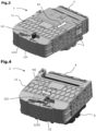
- Fig.1 shows the connector 2 with its slider 11 in open position, i.e. unengaged/unlocked position. While not accessible in its configuration, the CPA lock button 12 is in its unlocked stable position, in this example on the right side of its sliding path.
- the top wall 13 has an opening 120, which is partially covered by a shelter 121.
- the connector is in condition for making the connection, for example for connecting the wires 10 a battery or a motor device.
- the connector 2 is first positioned on the counter connector 3, then the slider 11 is moved M1 according to the arrow on the right for mating the terminals with their respective counter terminals.
- the CPA button 12 is then pushed M2 , as shown by the left oriented arrow toward its locked stable position, here on the left side of its sliding path ( Fig.5 ).
- the unlocked position of the CPA button 12 extends enough out of the shelter 121 so that it may be pushed by an human finger, until it is hidden by the shelter which correspond to its locked position.
- the CPA being clearly hidden under the shelter, and not anymore available for pushing it, means that the electrical connection is completed, which actually fulfils the role of a CPA system.
- the shelter 121 leaves an open slit 1210 on the front face of the CPA button 120. This slit give a thin access, not enough for inserting a finger, to a small recess 122 in this front face.
- a thin tool such as a small screwdriver 29 may be inserted into the slit 1210 and into the recess 122 of the CPA locking button 12 and used for driving said button 12 out of the shelter and toward its unlocked position as shown by the arrow M3.
- the locking button 12 is protected from shocks, and also from involuntary actuating or from any tool-less action.
- the locking button 12 is thus accessible for actuating toward its unlocking position with a tool but not by a human finger, so that the mate assist member 11 can be manually actuated toward its engaged position, while it cannot be disengaged without a tool.
- the disclosure provides a connector that can be opened for mating without a tool, using it for assembling a vehicle or a subassembly may be done quickly and easily, even if delivered to the assembly station in a closed slider configuration. This is obtained while preventing an untrained person to disconnect such electrical power without some preparation: it may be assumed that a person that knows how to use a tool for unlocking the CPA button 12 should be sufficiently informed or trained to also have the knowledge of the necessary previous operations, such as shutting down the power before disconnecting the connector assembly 1.
- the locking member (12) used as a "connection when in its locking position, is accessible for actuating toward its unlocking position with a tool but not by a human finger, so that the mate assist member (11) can be manually actuated toward its engaged position, while it cannot be disengaged without a tool.
Landscapes
- Engineering & Computer Science (AREA)
- Computer Security & Cryptography (AREA)
- Details Of Connecting Devices For Male And Female Coupling (AREA)
Priority Applications (1)
| Application Number | Priority Date | Filing Date | Title |
|---|---|---|---|
| EP23181432.8A EP4485708A1 (fr) | 2023-06-26 | 2023-06-26 | Connecteur de puissance électrique avec verrouillage de la position de verrouillage de la position de contact, et procédé d'utilisation de ce connecteur dans une connexion |
Applications Claiming Priority (1)
| Application Number | Priority Date | Filing Date | Title |
|---|---|---|---|
| EP23181432.8A EP4485708A1 (fr) | 2023-06-26 | 2023-06-26 | Connecteur de puissance électrique avec verrouillage de la position de verrouillage de la position de contact, et procédé d'utilisation de ce connecteur dans une connexion |
Publications (1)
| Publication Number | Publication Date |
|---|---|
| EP4485708A1 true EP4485708A1 (fr) | 2025-01-01 |
Family
ID=87047821
Family Applications (1)
| Application Number | Title | Priority Date | Filing Date |
|---|---|---|---|
| EP23181432.8A Pending EP4485708A1 (fr) | 2023-06-26 | 2023-06-26 | Connecteur de puissance électrique avec verrouillage de la position de verrouillage de la position de contact, et procédé d'utilisation de ce connecteur dans une connexion |
Country Status (1)
| Country | Link |
|---|---|
| EP (1) | EP4485708A1 (fr) |
Citations (4)
| Publication number | Priority date | Publication date | Assignee | Title |
|---|---|---|---|---|
| WO2012156486A1 (fr) | 2011-05-18 | 2012-11-22 | Fci Automotive Holding | Ensemble de connecteur électrique et connecteur pour un tel ensemble |
| EP2690720A1 (fr) * | 2012-07-26 | 2014-01-29 | Amphenol Air LB | Connecteur pour câbles à assemblage rapide |
| KR20140064289A (ko) * | 2012-11-20 | 2014-05-28 | 한국단자공업 주식회사 | 레버타입 커넥터 |
| DE102017215516A1 (de) * | 2017-09-05 | 2019-03-07 | Te Connectivity Germany Gmbh | Elektrischer Steckverbinder mit Fingerentriegelungsschutz |
-
2023
- 2023-06-26 EP EP23181432.8A patent/EP4485708A1/fr active Pending
Patent Citations (4)
| Publication number | Priority date | Publication date | Assignee | Title |
|---|---|---|---|---|
| WO2012156486A1 (fr) | 2011-05-18 | 2012-11-22 | Fci Automotive Holding | Ensemble de connecteur électrique et connecteur pour un tel ensemble |
| EP2690720A1 (fr) * | 2012-07-26 | 2014-01-29 | Amphenol Air LB | Connecteur pour câbles à assemblage rapide |
| KR20140064289A (ko) * | 2012-11-20 | 2014-05-28 | 한국단자공업 주식회사 | 레버타입 커넥터 |
| DE102017215516A1 (de) * | 2017-09-05 | 2019-03-07 | Te Connectivity Germany Gmbh | Elektrischer Steckverbinder mit Fingerentriegelungsschutz |
Similar Documents
| Publication | Publication Date | Title |
|---|---|---|
| US8628344B2 (en) | Connector and terminal positioning mechanism | |
| US8192212B2 (en) | Electrical connector system with temporarily blocking during unmating of two connectors | |
| KR102556351B1 (ko) | 단자 접촉 보호 수단을 구비한 직각 커넥터 | |
| US9455523B1 (en) | Right angle connection assembly | |
| US6648669B1 (en) | Electrical connection with sequential disconnect | |
| EP0622869B1 (fr) | Dispositif de connecteur | |
| CN103004031B (zh) | 具有径向地作用的闩锁装置的插接式连接器 | |
| US8241052B2 (en) | Electrical connector system with power and command connectors | |
| CN112534651B (zh) | 具有端子位置保证装置的电连接器 | |
| CN110690625B (zh) | 连接器装置 | |
| CN110571567B (zh) | 分阶段释放的电连接器组件 | |
| CN107453125B (zh) | 用于电连接器的锁定装置和配备该装置的电连接器 | |
| JP2007149420A (ja) | レバー嵌合式コネクタ | |
| US5913691A (en) | Dual power/control connector | |
| EP3769377B1 (fr) | Élément d'assurance de position de connecteur | |
| CN112714984A (zh) | 电插入式连接件、车辆和用于锁定电插入式连接件的方法 | |
| US8323046B1 (en) | Bi-directional CPA member to prevent unmating of multiple connectors | |
| CN112673531A (zh) | 电连接器、插入式连接件、高压系统以及用于锁定电插入式连接件的方法 | |
| CN113826287B (zh) | 安全分离的插式连接器部件 | |
| EP4485708A1 (fr) | Connecteur de puissance électrique avec verrouillage de la position de verrouillage de la position de contact, et procédé d'utilisation de ce connecteur dans une connexion | |
| US20030186579A1 (en) | Connector and a connector assembly | |
| EP4618320A1 (fr) | Dispositif d'assurance de position d'élément de fixation et ensemble connecteur | |
| EP4462610A1 (fr) | Connecteur d'alimentation électrique et procédé de démoration de celui-ci | |
| WO2020183255A1 (fr) | Organe d'assurance de position de connecteur | |
| KR101632708B1 (ko) | 커넥터 어셈블리 |
Legal Events
| Date | Code | Title | Description |
|---|---|---|---|
| STAA | Information on the status of an ep patent application or granted ep patent |
Free format text: STATUS: UNKNOWN |
|
| PUAI | Public reference made under article 153(3) epc to a published international application that has entered the european phase |
Free format text: ORIGINAL CODE: 0009012 |
|
| STAA | Information on the status of an ep patent application or granted ep patent |
Free format text: STATUS: THE APPLICATION HAS BEEN PUBLISHED |
|
| AK | Designated contracting states |
Kind code of ref document: A1 Designated state(s): AL AT BE BG CH CY CZ DE DK EE ES FI FR GB GR HR HU IE IS IT LI LT LU LV MC ME MK MT NL NO PL PT RO RS SE SI SK SM TR |
|
| STAA | Information on the status of an ep patent application or granted ep patent |
Free format text: STATUS: REQUEST FOR EXAMINATION WAS MADE |
|
| 17P | Request for examination filed |
Effective date: 20250623 |