EP4485710A1 - Abgeschirmte keystone-stanzwinde - Google Patents
Abgeschirmte keystone-stanzwinde Download PDFInfo
- Publication number
- EP4485710A1 EP4485710A1 EP24185179.9A EP24185179A EP4485710A1 EP 4485710 A1 EP4485710 A1 EP 4485710A1 EP 24185179 A EP24185179 A EP 24185179A EP 4485710 A1 EP4485710 A1 EP 4485710A1
- Authority
- EP
- European Patent Office
- Prior art keywords
- assembly
- wire cover
- jack
- cable
- punchdown
- Prior art date
- Legal status (The legal status is an assumption and is not a legal conclusion. Google has not performed a legal analysis and makes no representation as to the accuracy of the status listed.)
- Pending
Links
Images











Classifications
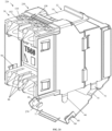
-
- H—ELECTRICITY
- H01—ELECTRIC ELEMENTS
- H01R—ELECTRICALLY-CONDUCTIVE CONNECTIONS; STRUCTURAL ASSOCIATIONS OF A PLURALITY OF MUTUALLY-INSULATED ELECTRICAL CONNECTING ELEMENTS; COUPLING DEVICES; CURRENT COLLECTORS
- H01R13/00—Details of coupling devices of the kinds covered by groups H01R12/70 or H01R24/00 - H01R33/00
- H01R13/648—Protective earth or shield arrangements on coupling devices, e.g. anti-static shielding
- H01R13/658—High frequency shielding arrangements, e.g. against EMI [Electro-Magnetic Interference] or EMP [Electro-Magnetic Pulse]
- H01R13/6591—Specific features or arrangements of connection of shield to conductive members
- H01R13/65912—Specific features or arrangements of connection of shield to conductive members for shielded multiconductor cable
- H01R13/65917—Connection to shield by means of resilient members
-
- H—ELECTRICITY
- H01—ELECTRIC ELEMENTS
- H01R—ELECTRICALLY-CONDUCTIVE CONNECTIONS; STRUCTURAL ASSOCIATIONS OF A PLURALITY OF MUTUALLY-INSULATED ELECTRICAL CONNECTING ELEMENTS; COUPLING DEVICES; CURRENT COLLECTORS
- H01R13/00—Details of coupling devices of the kinds covered by groups H01R12/70 or H01R24/00 - H01R33/00
- H01R13/648—Protective earth or shield arrangements on coupling devices, e.g. anti-static shielding
- H01R13/658—High frequency shielding arrangements, e.g. against EMI [Electro-Magnetic Interference] or EMP [Electro-Magnetic Pulse]
- H01R13/6591—Specific features or arrangements of connection of shield to conductive members
- H01R13/65912—Specific features or arrangements of connection of shield to conductive members for shielded multiconductor cable
- H01R13/65915—Twisted pair of conductors surrounded by shield
-
- H—ELECTRICITY
- H01—ELECTRIC ELEMENTS
- H01R—ELECTRICALLY-CONDUCTIVE CONNECTIONS; STRUCTURAL ASSOCIATIONS OF A PLURALITY OF MUTUALLY-INSULATED ELECTRICAL CONNECTING ELEMENTS; COUPLING DEVICES; CURRENT COLLECTORS
- H01R24/00—Two-part coupling devices, or either of their cooperating parts, characterised by their overall structure
- H01R24/60—Contacts spaced along planar side wall transverse to longitudinal axis of engagement
- H01R24/62—Sliding engagements with one side only, e.g. modular jack coupling devices
- H01R24/64—Sliding engagements with one side only, e.g. modular jack coupling devices for high frequency, e.g. RJ 45
-
- H—ELECTRICITY
- H01—ELECTRIC ELEMENTS
- H01R—ELECTRICALLY-CONDUCTIVE CONNECTIONS; STRUCTURAL ASSOCIATIONS OF A PLURALITY OF MUTUALLY-INSULATED ELECTRICAL CONNECTING ELEMENTS; COUPLING DEVICES; CURRENT COLLECTORS
- H01R4/00—Electrically-conductive connections between two or more conductive members in direct contact, i.e. touching one another; Means for effecting or maintaining such contact; Electrically-conductive connections having two or more spaced connecting locations for conductors and using contact members penetrating insulation
- H01R4/24—Connections using contact members penetrating or cutting insulation or cable strands
- H01R4/2416—Connections using contact members penetrating or cutting insulation or cable strands the contact members having insulation-cutting edges, e.g. of tuning fork type
- H01R4/242—Connections using contact members penetrating or cutting insulation or cable strands the contact members having insulation-cutting edges, e.g. of tuning fork type the contact members being plates having a single slot
- H01R4/2425—Flat plates, e.g. multi-layered flat plates
- H01R4/2429—Flat plates, e.g. multi-layered flat plates mounted in an insulating base
- H01R4/2433—Flat plates, e.g. multi-layered flat plates mounted in an insulating base one part of the base being movable to push the cable into the slot
Definitions
- the present invention is related generally to RJ45 style connectors and more specifically to a keystone style punchdown jack with a rear wire cover assembly.
- Mini-Com shielded TG jack modules and several unshielded keystone style punchdown jack modules. What is needed is a shielded keystone jack that utilizes the existing punchdown style termination method and is cost competitive to existing shielded Mini-Com jacks with a TG style termination method. Specifically, one with a rear wire cover assembly that can electrically connect a braid of a shielded cable to the shield of the jack and secure conductors to the shield of the jack.
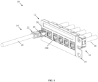
- FIG. 1 is an isometric view of communications system 10 which includes shielded patch panel 12, patch cord assembly 14, and terminated jack assemblies 16.
- Communications system 10,210 can further include cabinets, racks, cable management, patch panels, overhead routing systems, horizontal cabling, and other such equipment.
- Shielded patch panel 12 includes formed metal panel 18 and faceplate insert 20.
- Patch cord assembly 14 includes shielded plug assembly 22 and shielded cable 24.
- FIG. 2 is an isometric exploded view of terminated jack assembly 16.
- Terminated jack assembly 16 includes shielded cable 24, jack housing assembly 26, and rear wire cover assembly 28.
- Shielded cable 24 includes cable jacket 87, conductors 88, conductor divider 89, and braid 94.
- FIG. 3 is a front top exploded view of jack housing assembly 26.
- FIG. 4 is a front bottom exploded view of jack housing assembly 26.
- FIG. 5 is a rear top exploded view of jack housing assembly 26.
- FIG. 6 is a rear bottom exploded view of jack housing assembly 26.
- Jack housing assembly 26 includes front shield wrap 30, jack housing 32, PCB assembly 34, rear sled 36, and wire map label 38 ( FIG. 5 - FIG. 6 ).
- FIG. 3 - FIG. 6 depict front shield wrap 30 in its open state prior to the final forming.
- PCB assembly 34 includes sled assembly 40, long IDCs 42, IDC Support 44, and PCB 46.
- PCB assembly 34 is constructed and utilized in a manner identical to current production unshielded keystone punchdown jack modules.
- FIG. 7 is a front top view of jack housing assembly 26 with front shield wrap 30 in its open state prior to the final assembly.
- FIG. 8 is a front bottom view of jack housing assembly 26 with front shield wrap 30 in its open state.
- FIG. 9 is a rear top view of jack housing assembly 26 with front shield wrap 30 in its open state.
- FIG. 10 is a rear bottom view of jack housing assembly 26 with front shield wrap 30 in its open state.
- Rear tabs 66 pass through holes 68 as flange 70 is brought to a final position for front shield wrap 30. Rear tabs 66 are then formed over edges 69 of holes 68 to secure front shield wrap 30 in a locked position.
- Front tabs 72 are formed over offset geometry 74 on flange 70 of front shield wrap 30 for added security and shielding continuity.
- FIG. 15 is a front top exploded view of rear wire cover assembly 28.
- FIG. 16 is a rear bottom exploded view of rear wire cover assembly 28.
- Rear wire cover assembly 28 includes wire cover 76 and wire cover shield wrap 78. Wire cover 76 is placed into wire cover shield wrap 78. Return flanges 80 on wire cover shield wrap 78 catch to flat edges 82 on wire cover 76 to secure the components together.
- FIG. 17 is a front top view of rear wire cover assembly 28.
- Rear wire cover assembly 28 is symmetrically designed to allow cable opening 90 to point to either the left or right after final assembly.
- FIG. 18 is a section view of communications system 10 taken about the center line of conductor 88 4 and conductor 88 7 of an unmated terminated jack assembly 16 secured to shielded patch panel 12.
- Conductors 88 on shielded cable 24 are pressed into slots 86 ( FIG. 7 - FIG. 14 ) of rear sled 36 and terminated to long IDCs 42 of jack housing assembly 26.
- Cut edge 108 on rear sled 36 provides a flat surface for a punchdown tool to trim conductors 88 flush.
- Cable opening 90 on rear wire cover assembly 28 allows for rear wire cover assembly 28 to be placed onto jack housing assembly 26 after shielded cable 24 has been terminated to long IDCs 42 of jack housing assembly 26.
- Rear wire cover assembly 28 is then placed over the back end of jack housing assembly 26. If the ends of conductors 88 are cut too long or cut without the use of a punchdown tool after termination; rounded surfaces 109 on wire cover 76 of rear wire cover assembly 28 help to push excess conductor or dielectric length into overflow channels 110 on rear sled 36 of jack housing assembly 26.
- Capture slots 100 ( FIG. 15 - FIG. 17 ) on wire cover 76 of rear wire cover assembly 28 pass over round bosses 102 ( FIG. 7 - FIG. 14 ) on rear sled 36 of jack housing assembly 26 and secure rear wire cover assembly 28 to finalize terminated jack assembly 16.
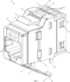
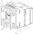
- FIG. 19 is a front top view of terminated jack assembly 16.
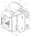
- FIG. 20 is a rear top view of terminated jack assembly 16.
- Inner wiping tabs 104 provide a bond between plug shield 23 ( FIG. 1 ) on shielded plug assembly 22 when shielded plug assembly 22 and terminated jack assembly 16 are in a mated state.
- Grounding tabs 106 are designed to bond terminated jack assembly 16 to shielded patch panel 12 when parts are assembled.
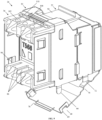
- FIG. 21 is a rear top view of alternate terminated jack assembly 17.
- Terminated jack assembly 17 includes all of the same components as terminated jack assembly 16, with the exception of alternate wire cover shield wrap 79.
- Alternate wire cover shield wrap 79 has identical internal geometry as wire cover shield wrap 78, but instead of inward facing grounding prongs 92, alternate wire cover shield wrap 79 includes grounding flange 93.
- Grounding flange 93 is an outward facing flange designed to bond around braid 94 of shielded cable 24 with the aid of a cable tie (not pictured).
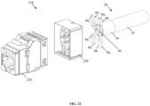
- FIG. 22 is an isometric exploded view of alternate embodiment terminated jack assembly 216.
- FIGS. 23 and 24 show alternate terminated jack assembly 216 with jack housing assembly 226 which is similar to jack housing assembly 26 except front shield wrap 230 has cutouts 271 on flange 270.
- FIG. 25 is a front top exploded view of alternate rear wire cover assembly 228.
- FIG. 26 is a rear bottom exploded view of rear wire cover assembly 228.
- Rear wire cover assembly 228 includes wire cover 276 and wire cover shield wrap 278. Wire cover 276 is placed into wire cover shield wrap 278. Wire cover shield wrap 278 is shown in its open position prior to final assembly. Securing flanges 280 on wire cover shield wrap 278 pass through slots 282 on wire cover 276 and are formed around edges 277 to secure the components together. Spring latches 281 on wire cover 276 help to contain securing flanges 280 after they are formed into their final position.
- FIG. 27 is a front top view of rear wire cover assembly 228 in its final assembled state.
- Rear wire cover assembly 228 is symmetrically designed and can be assembled to jack housing assembly 226 in the orientation shown or rotated 180-degrees about the central axis.
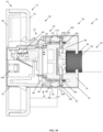
- FIG. 28 is a section view of communications system 210 taken about the center line of conductor 88 4 and conductor 88 7 of an unmated terminated jack assembly 216 secured to shielded patch panel 12.
- Conductors 88 on shielded cable 24 are pressed into slots 86 ( FIG. 7 - FIG. 14 ) of rear sled 36 and terminated to long IDCs 42 of jack housing assembly 226.
- Cut edge 108 on rear sled 36 provides a flat surface for a punchdown tool to trim conductors 88 flush.
- Shielded cable 24 has to be fed through rear wire cover assembly 228 prior to conductors 88 getting terminated to long IDCs 42 of jack housing assembly 226.
- Rear wire cover assembly 228 is then placed over the back end of jack housing assembly 226. If the ends of conductors 88 are cut too long or cut without the use of a punchdown tool after termination; angled faces 110 ( FIG. 7 - FIG. 14 ) allow users to trim excess length of conductors 88 with a pair of flat edge snips.
- Copper foil tape 294 is adhered over either a braid or drain wire from shielded cable 24 to create a smooth electrically conductive bonding surface.
- Grounding prongs 292 on wire cover shield wrap 278 of rear wire cover assembly 228 bond to copper foil tape 294 of shielded cable 24 as wire cover shield wrap 278 is placed into its final position to provide 360-degree shielding.
- Mandrels 290 on wire cover 276 provide a controlled surface for grounding prongs 292 on wire cover shield wrap 278 to wrap around and prevent plastic deformation, as shielded cable 24 is placed into rear wire cover assembly 228. Preventing grounding prongs 292 from plastically deforming ensures continuity between rear wire cover assembly 228 and copper foil tape 294 if a plurality of terminations occurs.
- Wiping tabs 96 ( FIG. 23 - FIG. 24 ) on front shield wrap 230 of jack housing assembly 226 make connection to inside walls 298 ( FIG. 25 - FIG. 27 ) on wire cover shield wrap 278 of rear wire cover assembly 228 to create a fully bonded assembly.
- Capture slots 300 ( FIG. 25 - FIG. 27 ) on wire cover 276 of rear wire cover assembly 228 pass over round bosses 102 ( FIG. 7 - FIG. 14 ) on rear sled 36 of jack housing assembly 226 and secure rear wire cover assembly 228 to finalize terminated jack assembly 216.
- Divider walls 284 on wire cover 276 of rear wire cover assembly 228 slide into slots 286 of rear sled 36 of jack housing assembly 226 and help to secure conductors 88 on shielded cable 24.
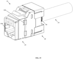
- FIG. 29 is a front top view of terminated jack assembly 216.
- FIG. 30 is a rear top view of terminated jack assembly 216.
- Inner wiping tabs 104 provide a bond between plug shield 23 ( FIG. 1 ) on shielded plug assembly 22 when shielded plug assembly 22 and terminated jack assembly 216 are in a mated state.
- Grounding tabs 106 are designed to bond terminated jack assembly 216 to shielded patch panel 12 when parts are assembled.
Landscapes
- Details Of Connecting Devices For Male And Female Coupling (AREA)
- Multi-Conductor Connections (AREA)
- Coupling Device And Connection With Printed Circuit (AREA)
Applications Claiming Priority (1)
| Application Number | Priority Date | Filing Date | Title |
|---|---|---|---|
| US18/216,252 US20240243524A1 (en) | 2023-01-18 | 2023-06-29 | Shielded keystone style punchdown jack |
Publications (1)
| Publication Number | Publication Date |
|---|---|
| EP4485710A1 true EP4485710A1 (de) | 2025-01-01 |
Family
ID=91738837
Family Applications (1)
| Application Number | Title | Priority Date | Filing Date |
|---|---|---|---|
| EP24185179.9A Pending EP4485710A1 (de) | 2023-06-29 | 2024-06-28 | Abgeschirmte keystone-stanzwinde |
Country Status (4)
| Country | Link |
|---|---|
| EP (1) | EP4485710A1 (de) |
| JP (1) | JP2025010001A (de) |
| CN (1) | CN223297159U (de) |
| TW (1) | TW202504187A (de) |
Citations (2)
| Publication number | Priority date | Publication date | Assignee | Title |
|---|---|---|---|---|
| US20160056547A1 (en) * | 2011-11-16 | 2016-02-25 | Panduit Corp. | High Bandwidth Jack wtih RJ45 Backwards Compatibility |
| US20190190218A1 (en) * | 2016-08-15 | 2019-06-20 | Commscope Technologies Llc | Connector assembly with grounding |
-
2024
- 2024-05-29 TW TW113119790A patent/TW202504187A/zh unknown
- 2024-06-27 JP JP2024103909A patent/JP2025010001A/ja active Pending
- 2024-06-27 CN CN202421498759.2U patent/CN223297159U/zh active Active
- 2024-06-28 EP EP24185179.9A patent/EP4485710A1/de active Pending
Patent Citations (2)
| Publication number | Priority date | Publication date | Assignee | Title |
|---|---|---|---|---|
| US20160056547A1 (en) * | 2011-11-16 | 2016-02-25 | Panduit Corp. | High Bandwidth Jack wtih RJ45 Backwards Compatibility |
| US20190190218A1 (en) * | 2016-08-15 | 2019-06-20 | Commscope Technologies Llc | Connector assembly with grounding |
Also Published As
| Publication number | Publication date |
|---|---|
| CN223297159U (zh) | 2025-09-02 |
| JP2025010001A (ja) | 2025-01-20 |
| TW202504187A (zh) | 2025-01-16 |
Similar Documents
| Publication | Publication Date | Title |
|---|---|---|
| CN216529380U (zh) | 通信连接器 | |
| US7033219B2 (en) | Modular plug assemblies, terminated cable assemblies and methods for forming the same | |
| US7510439B2 (en) | Shielded jack assemblies and methods for forming a cable termination | |
| US4533199A (en) | IDC termination for coaxial cable | |
| US5562493A (en) | Network interface assembly and mounting frame | |
| US8650750B2 (en) | Process for assembling a data cable connector module | |
| EP0793297A2 (de) | System zum Anschliessen der Abschirmung eines Kabels für hohe Übertragungsgeschwindigkeiten | |
| US4533193A (en) | IDC termination for coaxial cable having alignment & stabilizing means | |
| DE3751960T2 (de) | Schnittstelle für ein lokales Netz (LAN) | |
| US6213808B1 (en) | Method of joining electrical conductors and an apparatus for practicing this method | |
| JPH01501825A (ja) | 電気コネクタ | |
| US6354872B1 (en) | Cable connectors with modular shielding | |
| EP4485710A1 (de) | Abgeschirmte keystone-stanzwinde | |
| US20240243524A1 (en) | Shielded keystone style punchdown jack | |
| US20240243526A1 (en) | Shielded keystone style punchdown jack | |
| US12322914B2 (en) | Field terminable single pair ethernet connector with angled contacts | |
| CN100539323C (zh) | 插座组件和用于制作该插座组件的方法 | |
| EP0197994B1 (de) | Abgeschirmter elektrischer verbinder | |
| US20230057001A1 (en) | Field terminable ethernet connector with integral termination cap |
Legal Events
| Date | Code | Title | Description |
|---|---|---|---|
| PUAI | Public reference made under article 153(3) epc to a published international application that has entered the european phase |
Free format text: ORIGINAL CODE: 0009012 |
|
| STAA | Information on the status of an ep patent application or granted ep patent |
Free format text: STATUS: THE APPLICATION HAS BEEN PUBLISHED |
|
| AK | Designated contracting states |
Kind code of ref document: A1 Designated state(s): AL AT BE BG CH CY CZ DE DK EE ES FI FR GB GR HR HU IE IS IT LI LT LU LV MC ME MK MT NL NO PL PT RO RS SE SI SK SM TR |
|
| STAA | Information on the status of an ep patent application or granted ep patent |
Free format text: STATUS: REQUEST FOR EXAMINATION WAS MADE |
|
| 17P | Request for examination filed |
Effective date: 20250625 |