EP4485756A1 - Ensemble d'aimants permanents pour une machine à flux axial d'un entraînement de porte et machine à flux axial - Google Patents
Ensemble d'aimants permanents pour une machine à flux axial d'un entraînement de porte et machine à flux axial Download PDFInfo
- Publication number
- EP4485756A1 EP4485756A1 EP23181715.6A EP23181715A EP4485756A1 EP 4485756 A1 EP4485756 A1 EP 4485756A1 EP 23181715 A EP23181715 A EP 23181715A EP 4485756 A1 EP4485756 A1 EP 4485756A1
- Authority
- EP
- European Patent Office
- Prior art keywords
- permanent magnet
- magnet arrangement
- arrangement
- machine
- machine axis
- Prior art date
- Legal status (The legal status is an assumption and is not a legal conclusion. Google has not performed a legal analysis and makes no representation as to the accuracy of the status listed.)
- Pending
Links
Images

Classifications
-
- H—ELECTRICITY
- H02—GENERATION; CONVERSION OR DISTRIBUTION OF ELECTRIC POWER
- H02K—DYNAMO-ELECTRIC MACHINES
- H02K1/00—Details of the magnetic circuit
- H02K1/06—Details of the magnetic circuit characterised by the shape, form or construction
- H02K1/22—Rotating parts of the magnetic circuit
- H02K1/27—Rotor cores with permanent magnets
- H02K1/2793—Rotors axially facing stators
- H02K1/2795—Rotors axially facing stators the rotor consisting of two or more circumferentially positioned magnets
-
- E—FIXED CONSTRUCTIONS
- E05—LOCKS; KEYS; WINDOW OR DOOR FITTINGS; SAFES
- E05F—DEVICES FOR MOVING WINGS INTO OPEN OR CLOSED POSITION; CHECKS FOR WINGS; WING FITTINGS NOT OTHERWISE PROVIDED FOR, CONCERNED WITH THE FUNCTIONING OF THE WING
- E05F15/00—Power-operated mechanisms for wings
- E05F15/60—Power-operated mechanisms for wings using electrical actuators
- E05F15/603—Power-operated mechanisms for wings using electrical actuators using rotary electromotors
-
- H—ELECTRICITY
- H02—GENERATION; CONVERSION OR DISTRIBUTION OF ELECTRIC POWER
- H02K—DYNAMO-ELECTRIC MACHINES
- H02K21/00—Synchronous motors having permanent magnets; Synchronous generators having permanent magnets
- H02K21/12—Synchronous motors having permanent magnets; Synchronous generators having permanent magnets with stationary armatures and rotating magnets
- H02K21/24—Synchronous motors having permanent magnets; Synchronous generators having permanent magnets with stationary armatures and rotating magnets with magnets axially facing the armatures, e.g. hub-type cycle dynamos
-
- H—ELECTRICITY
- H02—GENERATION; CONVERSION OR DISTRIBUTION OF ELECTRIC POWER
- H02K—DYNAMO-ELECTRIC MACHINES
- H02K29/00—Motors or generators having non-mechanical commutating devices, e.g. discharge tubes or semiconductor devices
- H02K29/03—Motors or generators having non-mechanical commutating devices, e.g. discharge tubes or semiconductor devices with a magnetic circuit specially adapted for avoiding torque ripples or self-starting problems
Definitions
- the invention relates to a permanent magnet arrangement for use as a rotor or stator of an axial flux machine, in particular an axial flux machine of a door drive, wherein the permanent magnet arrangement has a plurality of permanent magnets arranged in a ring around a machine axis and each magnetized in an axial direction running parallel to the machine axis, wherein permanent magnets arranged adjacent to one another each have an oppositely oriented polarization, wherein each permanent magnet extends from an inner surface of the permanent magnet facing the machine axis to an outer surface of the permanent magnet, wherein each permanent magnet has a first side surface and a second side surface opposite the first side surface, wherein the two side surfaces connect the inner surface and the outer surface to one another, wherein the first side surface of each permanent magnet is oriented in the direction of the second side surface of a respective immediately adjacent permanent magnet.
- the invention also relates to an axial flux machine with a coil arrangement and a permanent magnet arrangement.
- axial flux machines and in particular of brushless axial flux machines for door drives is known from the state of the art and is described, for example, in the publication EP 3 974 610 A1
- the magnetic flux runs through the permanent magnet arrangement and the coil arrangement axially to the Rotational axis of the motor, which forms the machine axis.
- the permanent magnet arrangement forms part of a stator of the axial flux machine and the coil arrangement forms part of a rotor of the axial flux machine or the permanent magnet arrangement forms part of the rotor of the axial flux machine and the coil arrangement forms part of the stator of the axial flux machine.
- the permanent magnets of the permanent magnet arrangement and coils of the coil arrangement are usually arranged in a ring around the machine axis.
- the permanent magnets are aligned so that one of the poles of each permanent magnet is closer to the coil arrangement than the other pole, so that magnetic field lines running between the north pole and the south pole within the respective permanent magnet run parallel to the machine axis.
- the permanent magnets usually have an approximately trapezoidal base area, with dimensions of the base area being a multiple of a height of the respective permanent magnet. Straight lines through side edges of the base area usually run through a point on the rotational axis or the machine axis, so that an inner edge of the base area is shorter than an outer edge of the base area.
- the permanent magnets therefore have the shape of an approximately trapezoidal prism.
- the inner edge and the outer edge are often also shaped like a circular segment, so that the base area forms a ring segment.
- the permanent magnets of the permanent magnet arrangement according to the invention each have an inner surface, an outer surface and opposing side surfaces. These can be clearly separated from one another.
- cogging forces are magnetic interference forces and are caused by interactions between the permanent magnets and coil cores or stator teeth, which are made of iron or another material with good magnetic conductivity.
- Various measures are known from the state of the art to reduce these cogging forces.
- the permanent magnets are adjusted from the approximately trapezoidal base area so that the straight lines through the side edges no longer run through the axis of rotation, or that shapes deviating from the trapezoidal shape are selected, for example with bent side edges.
- beveling the magnetic edges is to adjust the permanent magnets from the trapezoidal base area so that the side edges are tilted against the straight lines running through the axis of rotation by a so-called bevel angle.
- the side edges of the permanent magnets have the same displacement angle for each connection point on the respective side edge or at least for each connection point on sections of the side edges when the side edge is bent. This is also called the bevel angle.
- the object of the invention is to further develop the designs of the magnetic edges known from the prior art in such a way that the cogging torques are further reduced.
- each first side surface has a continuously curved course from the inner surface to the outer surface, so that the course of the first side surface is either concave or convex.
- inventive design of at least one of the two side surfaces exploits this knowledge to further reduce the cogging torques. For this purpose, instead of the design with a constant displacement or helix angle, at least one of the side surfaces is designed in such a way that the helix angle increases continuously with the distance from the machine axis and is curved.
- the cogging torques can advantageously be further reduced by increasing the curvature of the first side surface from the inner surface to the outer surface. It has been shown that by designing a side surface in this way with a cogging torque that increases disproportionately depending on the distance from the machine axis, Helix angles allow the cogging torques to be reduced particularly well.
- every second side surface has a continuously curved profile from the inner surface to the outer surface, so that the profile of the second side surface is either convex or concave.
- the second side surface is also inclined or tilted or slanted and curved.
- a curvature of the second side surface increases from the inner surface to the outer surface. In this way, the helix angle of the second side surface changes disproportionately in relation to the distance of the respective section from the machine axis, as with the first side surface.
- the invention provides that the profile of the second side surface is concave when the profile of the first side surface is convex and vice versa.
- the second side surface is inclined or tilted or beveled in the same direction as the first side surface.
- the cogging torques can be further reduced by increasing a distance, determined in a circumferential direction of the permanent magnet arrangement, between the first side surface and the second side surface of each permanent magnet from the inner surface to the outer surface.
- the first displacement angle increases in relation to the distance of the respective displacement point from the machine axis more than the second displacement angle decreases.
- the invention provides that all cutting planes of each permanent magnet that are perpendicular to the machine axis are congruent. As a result, all first connecting lines of the same length have the same first displacement angle and all second connecting lines of the same length have the same second displacement angle. This results in both side surfaces being curved or stepped exclusively in one circumferential direction.
- each permanent magnet runs in sections along an inner ring circumference of the permanent magnet arrangement and the outer surface of each permanent magnet runs in sections along an outer ring circumference of the permanent magnet arrangement.
- the ring-shaped design of the permanent magnet arrangement results in a magnetic field that is particularly suitable for the axial flux machine.
- the permanent magnets are designed in such a way and the inner surfaces and the outer surfaces of each permanent magnet are aligned with each other in such a way that in at least one cutting plane perpendicular to the machine axis, a radially extending through a A ray running from the inner distance center of the inner surface of each permanent magnet intersects the outer surface or the outer ring circumference of the respective permanent magnet at a distance from an outer distance center, wherein the inner distance center and the outer distance center are determined by the average path length between end points of the respective inner surface or the respective outer surface.
- the invention provides that the outer surface is displaced in the circumferential direction relative to the inner surface. This displacement relates to the approximately trapezoidal basic shape of the permanent magnets known from the prior art.
- the invention provides that a length of the outer surface in the circumferential direction is greater than a length of the inner surface. In this way, the available installation space can be fully utilized.
- the cogging torques can be further reduced by designing the permanent magnets and aligning them relative to one another in such a way that, in at least one cutting plane perpendicular to the machine axis, a beam running radially from the machine axis through an outermost point in the circumferential direction of the outer surface of a first permanent magnet runs in sections in the corresponding cutting plane of a second permanent magnet arranged immediately adjacent to the first permanent magnet. Adjacent permanent magnets As a result, they overlap in sections when viewed from the machine axis.
- the outer surface and the inner surface of the permanent magnet do not merge continuously into one another.
- the inner surface and the outer surface can advantageously be clearly demarcated from one another and from the side surfaces.
- the side surfaces do not merge continuously into the inner surface and the outer surface.
- the invention also relates to an axial flux machine with a coil arrangement and a permanent magnet arrangement according to one of the preceding claims, wherein the coil arrangement has a plurality of electrical machine coils arranged adjacent to one another in a ring around the machine axis, wherein the coil arrangement is arranged axially displaced, adjacent to the permanent magnet arrangement.
- the axial flux machine is advantageously a brushless axial flux machine. Such axial flux machines are particularly suitable for use with door or window drives.
- the invention provides that the inner ring circumference and the outer ring circumference of the permanent magnet arrangement correspond essentially to corresponding ring circumferences of the coil arrangement. In this way, a particularly compact design of the axial flux machine can be achieved. According to the invention, it is advantageously provided that the axial flow machine can be used in a swing door, sliding door or revolving door drive.
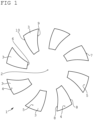
- Figure 1 a schematic representation of a permanent magnet arrangement with permanent magnets that have a continuous course of the side surfaces
- Figure 2 a schematic representation of an axial flow machine.
- a permanent magnet arrangement 1 for an axial flux machine of a door drive is shown schematically.
- the permanent magnet arrangement 1 has several permanent magnets 3 arranged adjacent to one another in a ring around a machine axis 2.
- a magnetic north pole 4 and a magnetic south pole 5 of each permanent magnet 3 are arranged such that within the respective permanent magnet 3, magnetic field lines running between the north pole 4 and the south pole 5 run parallel to the machine axis 2, with magnetic field directions of adjacent permanent magnets 3 running in opposite directions.
- Each permanent magnet 3 extends from an inner surface 6 facing the machine axis 2 to an outer surface 7.
- the inner surface 6 and the outer surface 7 are each connected by the north pole 4 to the south pole 5. extending side surfaces 8 of the respective permanent magnet 3.
- First side surfaces 9 and second side surfaces 10 have a continuous curved course in a circumferential direction of the permanent magnet arrangement 1 from the inner surface 6 to the outer surface 7, wherein the first side surface 9 is concavely curved and the second side surface 10 is convexly curved. In this case, a distance between the side surfaces 9, 10 in the circumferential direction of the permanent magnet arrangement 1 increases in the radial direction.
- each permanent magnet 3 is curved and run along an inner ring circumference and an outer ring circumference of the permanent magnet arrangement 1.
- the outer surfaces 7 are displaced relative to the inner surface 6 in the circumferential direction.
- a length of the outer surfaces 7 in the circumferential direction is greater than a length of the inner surfaces 6.
- Figure 2 shows schematically a partially sectioned axial flow machine 11 with a coil arrangement 12 and a permanent magnet arrangement 1.
- the permanent magnet arrangement 1 corresponds to the one shown in Figure 1 illustrated design. In this illustration it can be seen that all cutting planes of each permanent magnet 3 that are perpendicular to the machine axis 2 are congruent.
- the coil arrangement 12 has a plurality of electrical Machine coils 13 that are wound around iron cores 14 of the coil arrangement 12.
- the coil arrangement 12 is axially displaced, arranged adjacent to the permanent magnet arrangement 1.
- the axial flux machine 11 also has a circuit board 15 for electrically contacting the coils 13.
Landscapes
- Engineering & Computer Science (AREA)
- Power Engineering (AREA)
- Permanent Field Magnets Of Synchronous Machinery (AREA)
Priority Applications (2)
| Application Number | Priority Date | Filing Date | Title |
|---|---|---|---|
| EP23181715.6A EP4485756A1 (fr) | 2023-06-27 | 2023-06-27 | Ensemble d'aimants permanents pour une machine à flux axial d'un entraînement de porte et machine à flux axial |
| US18/752,150 US20250007341A1 (en) | 2023-06-27 | 2024-06-24 | Permanent magnet arrangement for an axial flux machine of a door drive and axial flux machine |
Applications Claiming Priority (1)
| Application Number | Priority Date | Filing Date | Title |
|---|---|---|---|
| EP23181715.6A EP4485756A1 (fr) | 2023-06-27 | 2023-06-27 | Ensemble d'aimants permanents pour une machine à flux axial d'un entraînement de porte et machine à flux axial |
Publications (1)
| Publication Number | Publication Date |
|---|---|
| EP4485756A1 true EP4485756A1 (fr) | 2025-01-01 |
Family
ID=87003267
Family Applications (1)
| Application Number | Title | Priority Date | Filing Date |
|---|---|---|---|
| EP23181715.6A Pending EP4485756A1 (fr) | 2023-06-27 | 2023-06-27 | Ensemble d'aimants permanents pour une machine à flux axial d'un entraînement de porte et machine à flux axial |
Country Status (2)
| Country | Link |
|---|---|
| US (1) | US20250007341A1 (fr) |
| EP (1) | EP4485756A1 (fr) |
Citations (6)
| Publication number | Priority date | Publication date | Assignee | Title |
|---|---|---|---|---|
| JPS50111611U (fr) * | 1974-02-22 | 1975-09-11 | ||
| EP0734112A1 (fr) * | 1995-03-24 | 1996-09-25 | Kone Oy | Enroulement d'amortissement pour un moteur d'élévateur |
| WO2009037374A1 (fr) * | 2007-09-21 | 2009-03-26 | Kone Corporation | Moteur électrique |
| EP3176914A1 (fr) * | 2010-03-31 | 2017-06-07 | Kone Corporation | Moteur électrique, appareil de levage et système d'ascenseur |
| EP3974610A1 (fr) | 2020-09-25 | 2022-03-30 | dormakaba Deutschland GmbH | Dispositif d'entraînement permettant de déplacer un battant |
| JP7289535B2 (ja) * | 2020-05-19 | 2023-06-12 | 株式会社アパード | アキシャルギャップモータ |
Family Cites Families (2)
| Publication number | Priority date | Publication date | Assignee | Title |
|---|---|---|---|---|
| DE102020125116A1 (de) * | 2020-09-25 | 2022-03-31 | Dormakaba Deutschland Gmbh | Stator für eine Axialflussmaschine, Axialflussmaschine und Antriebseinrichtung zum Bewegen eines Flügels |
| DE112022003168T5 (de) * | 2021-06-21 | 2024-05-29 | Sumitomo Electric Industries, Ltd. | Statorkern, Stator, sich drehende Elektromaschine und Verfahren zur Herstellung eines Statorkerns |
-
2023
- 2023-06-27 EP EP23181715.6A patent/EP4485756A1/fr active Pending
-
2024
- 2024-06-24 US US18/752,150 patent/US20250007341A1/en active Pending
Patent Citations (6)
| Publication number | Priority date | Publication date | Assignee | Title |
|---|---|---|---|---|
| JPS50111611U (fr) * | 1974-02-22 | 1975-09-11 | ||
| EP0734112A1 (fr) * | 1995-03-24 | 1996-09-25 | Kone Oy | Enroulement d'amortissement pour un moteur d'élévateur |
| WO2009037374A1 (fr) * | 2007-09-21 | 2009-03-26 | Kone Corporation | Moteur électrique |
| EP3176914A1 (fr) * | 2010-03-31 | 2017-06-07 | Kone Corporation | Moteur électrique, appareil de levage et système d'ascenseur |
| JP7289535B2 (ja) * | 2020-05-19 | 2023-06-12 | 株式会社アパード | アキシャルギャップモータ |
| EP3974610A1 (fr) | 2020-09-25 | 2022-03-30 | dormakaba Deutschland GmbH | Dispositif d'entraînement permettant de déplacer un battant |
Also Published As
| Publication number | Publication date |
|---|---|
| US20250007341A1 (en) | 2025-01-02 |
Similar Documents
| Publication | Publication Date | Title |
|---|---|---|
| DE102006025396B4 (de) | A-phasiger bürstenloser Motor | |
| EP0729216A2 (fr) | Machine synchrone à excitation hybride | |
| DE3710658A1 (de) | Elektronisch kommutierter, kollektorloser gleichstrommotor | |
| DE102010046906A1 (de) | Motor | |
| DE112011101641T5 (de) | Rotor einer rotierenden elektrischen Maschine | |
| WO2006106087A1 (fr) | Moteur a reluctance | |
| DE102015004669A1 (de) | Motor | |
| EP2725687A1 (fr) | Machine synchrone excitée en permanence | |
| DE102007013738B4 (de) | Elektrische Maschine mit Klauenpolstator | |
| WO2007115907A2 (fr) | Dispositif d'entraînement et d'évaluation | |
| DE10261763B4 (de) | Rotor für einen Elektromotor | |
| WO2021047956A1 (fr) | Rotor pour machine électrique | |
| DE102017109256A1 (de) | Statoranordnung | |
| DE102018112971A1 (de) | Permanentmagnet-Synchronmotor und Magnetpositionierungssystem für einen Verdichter einer Fahrzeugklimaanlage | |
| EP3758194B1 (fr) | Rotor pour une machine électrique, machine électrique pour un véhicule et véhicule | |
| EP4485756A1 (fr) | Ensemble d'aimants permanents pour une machine à flux axial d'un entraînement de porte et machine à flux axial | |
| EP4485755A1 (fr) | Ensemble d'aimants permanents pour une machine à flux axial d'un entraînement de porte et machine à flux axial | |
| DE102020212636A1 (de) | Rotor für eine elektrische Maschine, elektrische Maschine und Kraftfahrzeug | |
| DE102021125206A1 (de) | Elektromechanische Rotortopologie zur Steigerung der Effizienz elektrischer Maschinen | |
| DE102016212328A1 (de) | Rotoranordnung einer elektrischen Maschine | |
| DE10313970A1 (de) | Rotor für hohe Drehzahlen und große Ausgangsleistung | |
| DE60014199T2 (de) | Elektrische Drehmaschine | |
| WO2025242293A1 (fr) | Ensemble rotor pour moteur à flux axial et moteur à flux axial comprenant un ensemble rotor | |
| EP4485754A1 (fr) | Dispositif à aimant permanent, machine à flux axial et entraînement électromécanique | |
| DE10056875A1 (de) | Rotor für eine elektrische Maschine |
Legal Events
| Date | Code | Title | Description |
|---|---|---|---|
| PUAI | Public reference made under article 153(3) epc to a published international application that has entered the european phase |
Free format text: ORIGINAL CODE: 0009012 |
|
| STAA | Information on the status of an ep patent application or granted ep patent |
Free format text: STATUS: THE APPLICATION HAS BEEN PUBLISHED |
|
| AK | Designated contracting states |
Kind code of ref document: A1 Designated state(s): AL AT BE BG CH CY CZ DE DK EE ES FI FR GB GR HR HU IE IS IT LI LT LU LV MC ME MK MT NL NO PL PT RO RS SE SI SK SM TR |
|
| STAA | Information on the status of an ep patent application or granted ep patent |
Free format text: STATUS: REQUEST FOR EXAMINATION WAS MADE |
|
| 17P | Request for examination filed |
Effective date: 20250617 |