EP4485923A1 - Dispositif de codage d'image, dispositif de décodage d'image, procédé de codage d'image et procédé de décodage d'image - Google Patents
Dispositif de codage d'image, dispositif de décodage d'image, procédé de codage d'image et procédé de décodage d'image Download PDFInfo
- Publication number
- EP4485923A1 EP4485923A1 EP23780064.4A EP23780064A EP4485923A1 EP 4485923 A1 EP4485923 A1 EP 4485923A1 EP 23780064 A EP23780064 A EP 23780064A EP 4485923 A1 EP4485923 A1 EP 4485923A1
- Authority
- EP
- European Patent Office
- Prior art keywords
- filter
- image
- processing unit
- bit stream
- information
- Prior art date
- Legal status (The legal status is an assumption and is not a legal conclusion. Google has not performed a legal analysis and makes no representation as to the accuracy of the status listed.)
- Pending
Links
Images







Classifications
-
- H—ELECTRICITY
- H04—ELECTRIC COMMUNICATION TECHNIQUE
- H04N—PICTORIAL COMMUNICATION, e.g. TELEVISION
- H04N19/00—Methods or arrangements for coding, decoding, compressing or decompressing digital video signals
- H04N19/10—Methods or arrangements for coding, decoding, compressing or decompressing digital video signals using adaptive coding
- H04N19/102—Methods or arrangements for coding, decoding, compressing or decompressing digital video signals using adaptive coding characterised by the element, parameter or selection affected or controlled by the adaptive coding
- H04N19/117—Filters, e.g. for pre-processing or post-processing
-
- G—PHYSICS
- G06—COMPUTING OR CALCULATING; COUNTING
- G06T—IMAGE DATA PROCESSING OR GENERATION, IN GENERAL
- G06T3/00—Geometric image transformations in the plane of the image
- G06T3/40—Scaling of whole images or parts thereof, e.g. expanding or contracting
-
- G—PHYSICS
- G06—COMPUTING OR CALCULATING; COUNTING
- G06T—IMAGE DATA PROCESSING OR GENERATION, IN GENERAL
- G06T5/00—Image enhancement or restoration
- G06T5/20—Image enhancement or restoration using local operators
-
- G—PHYSICS
- G06—COMPUTING OR CALCULATING; COUNTING
- G06T—IMAGE DATA PROCESSING OR GENERATION, IN GENERAL
- G06T5/00—Image enhancement or restoration
- G06T5/70—Denoising; Smoothing
-
- H—ELECTRICITY
- H04—ELECTRIC COMMUNICATION TECHNIQUE
- H04N—PICTORIAL COMMUNICATION, e.g. TELEVISION
- H04N19/00—Methods or arrangements for coding, decoding, compressing or decompressing digital video signals
- H04N19/10—Methods or arrangements for coding, decoding, compressing or decompressing digital video signals using adaptive coding
- H04N19/102—Methods or arrangements for coding, decoding, compressing or decompressing digital video signals using adaptive coding characterised by the element, parameter or selection affected or controlled by the adaptive coding
- H04N19/132—Sampling, masking or truncation of coding units, e.g. adaptive resampling, frame skipping, frame interpolation or high-frequency transform coefficient masking
-
- H—ELECTRICITY
- H04—ELECTRIC COMMUNICATION TECHNIQUE
- H04N—PICTORIAL COMMUNICATION, e.g. TELEVISION
- H04N19/00—Methods or arrangements for coding, decoding, compressing or decompressing digital video signals
- H04N19/10—Methods or arrangements for coding, decoding, compressing or decompressing digital video signals using adaptive coding
- H04N19/169—Methods or arrangements for coding, decoding, compressing or decompressing digital video signals using adaptive coding characterised by the coding unit, i.e. the structural portion or semantic portion of the video signal being the object or the subject of the adaptive coding
- H04N19/17—Methods or arrangements for coding, decoding, compressing or decompressing digital video signals using adaptive coding characterised by the coding unit, i.e. the structural portion or semantic portion of the video signal being the object or the subject of the adaptive coding the unit being an image region, e.g. an object
-
- H—ELECTRICITY
- H04—ELECTRIC COMMUNICATION TECHNIQUE
- H04N—PICTORIAL COMMUNICATION, e.g. TELEVISION
- H04N19/00—Methods or arrangements for coding, decoding, compressing or decompressing digital video signals
- H04N19/10—Methods or arrangements for coding, decoding, compressing or decompressing digital video signals using adaptive coding
- H04N19/169—Methods or arrangements for coding, decoding, compressing or decompressing digital video signals using adaptive coding characterised by the coding unit, i.e. the structural portion or semantic portion of the video signal being the object or the subject of the adaptive coding
- H04N19/17—Methods or arrangements for coding, decoding, compressing or decompressing digital video signals using adaptive coding characterised by the coding unit, i.e. the structural portion or semantic portion of the video signal being the object or the subject of the adaptive coding the unit being an image region, e.g. an object
- H04N19/172—Methods or arrangements for coding, decoding, compressing or decompressing digital video signals using adaptive coding characterised by the coding unit, i.e. the structural portion or semantic portion of the video signal being the object or the subject of the adaptive coding the unit being an image region, e.g. an object the region being a picture, frame or field
-
- H—ELECTRICITY
- H04—ELECTRIC COMMUNICATION TECHNIQUE
- H04N—PICTORIAL COMMUNICATION, e.g. TELEVISION
- H04N19/00—Methods or arrangements for coding, decoding, compressing or decompressing digital video signals
- H04N19/10—Methods or arrangements for coding, decoding, compressing or decompressing digital video signals using adaptive coding
- H04N19/169—Methods or arrangements for coding, decoding, compressing or decompressing digital video signals using adaptive coding characterised by the coding unit, i.e. the structural portion or semantic portion of the video signal being the object or the subject of the adaptive coding
- H04N19/184—Methods or arrangements for coding, decoding, compressing or decompressing digital video signals using adaptive coding characterised by the coding unit, i.e. the structural portion or semantic portion of the video signal being the object or the subject of the adaptive coding the unit being bits, e.g. of the compressed video stream
-
- H—ELECTRICITY
- H04—ELECTRIC COMMUNICATION TECHNIQUE
- H04N—PICTORIAL COMMUNICATION, e.g. TELEVISION
- H04N19/00—Methods or arrangements for coding, decoding, compressing or decompressing digital video signals
- H04N19/46—Embedding additional information in the video signal during the compression process
-
- H—ELECTRICITY
- H04—ELECTRIC COMMUNICATION TECHNIQUE
- H04N—PICTORIAL COMMUNICATION, e.g. TELEVISION
- H04N19/00—Methods or arrangements for coding, decoding, compressing or decompressing digital video signals
- H04N19/70—Methods or arrangements for coding, decoding, compressing or decompressing digital video signals characterised by syntax aspects related to video coding, e.g. related to compression standards
-
- H—ELECTRICITY
- H04—ELECTRIC COMMUNICATION TECHNIQUE
- H04N—PICTORIAL COMMUNICATION, e.g. TELEVISION
- H04N19/00—Methods or arrangements for coding, decoding, compressing or decompressing digital video signals
- H04N19/80—Details of filtering operations specially adapted for video compression, e.g. for pixel interpolation
-
- H—ELECTRICITY
- H04—ELECTRIC COMMUNICATION TECHNIQUE
- H04N—PICTORIAL COMMUNICATION, e.g. TELEVISION
- H04N19/00—Methods or arrangements for coding, decoding, compressing or decompressing digital video signals
- H04N19/80—Details of filtering operations specially adapted for video compression, e.g. for pixel interpolation
- H04N19/82—Details of filtering operations specially adapted for video compression, e.g. for pixel interpolation involving filtering within a prediction loop
-
- H—ELECTRICITY
- H04—ELECTRIC COMMUNICATION TECHNIQUE
- H04N—PICTORIAL COMMUNICATION, e.g. TELEVISION
- H04N19/00—Methods or arrangements for coding, decoding, compressing or decompressing digital video signals
- H04N19/85—Methods or arrangements for coding, decoding, compressing or decompressing digital video signals using pre-processing or post-processing specially adapted for video compression
-
- H—ELECTRICITY
- H04—ELECTRIC COMMUNICATION TECHNIQUE
- H04N—PICTORIAL COMMUNICATION, e.g. TELEVISION
- H04N19/00—Methods or arrangements for coding, decoding, compressing or decompressing digital video signals
- H04N19/85—Methods or arrangements for coding, decoding, compressing or decompressing digital video signals using pre-processing or post-processing specially adapted for video compression
- H04N19/86—Methods or arrangements for coding, decoding, compressing or decompressing digital video signals using pre-processing or post-processing specially adapted for video compression involving reduction of coding artifacts, e.g. of blockiness
-
- G—PHYSICS
- G06—COMPUTING OR CALCULATING; COUNTING
- G06T—IMAGE DATA PROCESSING OR GENERATION, IN GENERAL
- G06T2207/00—Indexing scheme for image analysis or image enhancement
- G06T2207/20—Special algorithmic details
- G06T2207/20024—Filtering details
- G06T2207/20028—Bilateral filtering
-
- G—PHYSICS
- G06—COMPUTING OR CALCULATING; COUNTING
- G06T—IMAGE DATA PROCESSING OR GENERATION, IN GENERAL
- G06T2207/00—Indexing scheme for image analysis or image enhancement
- G06T2207/20—Special algorithmic details
- G06T2207/20024—Filtering details
- G06T2207/20032—Median filtering
-
- G—PHYSICS
- G06—COMPUTING OR CALCULATING; COUNTING
- G06T—IMAGE DATA PROCESSING OR GENERATION, IN GENERAL
- G06T2207/00—Indexing scheme for image analysis or image enhancement
- G06T2207/20—Special algorithmic details
- G06T2207/20084—Artificial neural networks [ANN]
Definitions
- the present disclosure relates to an image encoding device, an image decoding device, an image encoding method, and an image decoding method.
- Patent Literature 1 discloses a video encoding and decoding method using adaptive coupling pre-filters and post-filters.
- Patent Literature 2 discloses an encoding method of image data for loading into an artificial intelligence (AI) integrated circuit.
- AI artificial intelligence
- An object of the present disclosure is to improve bit efficiency of a bit stream transmitted from an image encoding device to an image decoding device.
- An image encoding device includes: a filter processing unit that performs filter processing on an input image to generate a first image; and an encoding processing unit that generates a bit stream by performing encoding processing on the first image and transmits the bit stream to an image decoding device, in which the filter processing unit: includes a plurality of filters of different types; and selects one filter from the plurality of filters based on usage information indicating image usage on the image decoding device side and applies the selected filter to the input image.
- the conventional encoding method has aimed to provide optimal video for human vision under bit rate constraints.
- VCM video coding for machines
- machines can communicate with each other and perform tasks without human intervention, while in other cases, additional processing by humans may be necessary for decompressed specific streams. For example, in surveillance cameras, when a human "supervisor" searches for a specific person or scene in a video, or the like.
- bit streams are used by both humans and machines.
- features can be used for image correction functions for humans and for the object detection and segmentation for machines.
- Typical system architecture includes a pair of image encoding device and image decoding device.
- the input of the system is a video, a still image, or a feature quantity.
- Examples of a machine task include object detection, object segmentation, object tracking, action recognition, pose estimation, or an arbitrary combination thereof. There is a possibility that human vision is one of the use cases that can be used along with the machine task.
- the present inventors have conceived the present disclosure based on the finding that by performing appropriate filter processing on an input image on the image encoding device side based on usage information indicating the image usage on the image decoding device side, it is possible to improve the bit efficiency in the transmission of the bit stream from the image encoding device to the image decoding device.
- An image encoding device includes: a filter processing unit that performs filter processing on an input image to generate a first image; and an encoding processing unit that generates a bit stream by performing encoding processing on the first image and transmits the bit stream to an image decoding device, in which the filter processing unit: includes a plurality of filters of different types; and selects one filter from the plurality of filters based on usage information indicating image usage on the image decoding device side and applies the selected filter to the input image.
- the filter processing unit includes the plurality of filters of different types, and selects one filter from the plurality of filters based on the usage information indicating the image usage on the image decoding device side and applies the selected filter to the input image.
- the plurality of filters includes at least one of a noise removal filter, a sharpening filter, a bit depth conversion filter, a color space conversion filter, a resolution conversion filter, and a filter using a neural network in the first aspect.
- the filter processing unit can apply an appropriate filter to the input image according to the image usage on the image decoding device side.
- the noise removal filter includes at least one of a low-pass filter, a Gaussian filter, a smoothing filter, an averaging filter, a bilateral filter, and a median filter in the second aspect.
- the third aspect by applying at least one of the low-pass filter, Gaussian filter, smoothing filter, averaging filter, bilateral filter, and median filter to the input image, it is possible to remove noise in the input image.
- the resolution conversion filter includes a downsampling filter that reduces resolution of the first image from resolution of the input image in the second aspect.
- the fourth aspect it is possible to reduce the code amount by applying the downsampling filter to the input image.
- the image usage includes at least one machine task and human vision in any one of the first to fourth aspects.
- the fifth aspect it is possible to make a selection to apply a filter that reduces the code amount when the image usage is the machine task, and to apply a filter that does not reduce the code amount as much as when the image usage is the machine task, when the image usage is the human vision.
- the filter processing unit reduces a code amount of the first image from a code amount of the input image by the filter processing in the fifth aspect.
- the sixth aspect it is possible to improve the bit efficiency in the transmission of the bit stream from the image encoding device to the image decoding device by applying the filter that reduces the code amount when the image usage is the machine task.
- the filter processing unit defines a non-important region that is not important for the machine task in the input image; and reduces the code amount of the first image from the code amount of the input image by deleting information on details of the non-important region in the sixth aspect.
- the seventh aspect by reducing the code amount of the first image through deletion of the information on details of the non-important region, there is no need to reduce the code amount of the important region, which is important for the machine task, making it possible to execute the machine task appropriately on the image decoding device side.
- the filter processing unit defines an important region that is important for the machine task in the input image; and emphasizes the important region by the filter processing in the sixth or seventh aspect.
- the filter processing unit emphasizes the important region by the filter processing, making it possible to execute the machine task appropriately on the image decoding device side.
- the filter processing unit does not reduce the code amount of the first image by the filter processing more than when the image usage is the machine task in the fifth aspect.
- the image usage is the human vision
- the encoding processing unit stores filter information about the filter applied by the filter processing unit to the input image in the bit stream in any one of the first to ninth aspect.
- the filter information about the filter applied to the input image in the bit stream by storing the filter information about the filter applied to the input image in the bit stream, it is possible to utilize the filter information in the machine task on the image decoding device side.
- the encoding processing unit stores the filter information in a header of the bit stream in the tenth aspect.
- the image decoding device can easily extract the filter information from the bit stream.
- the header includes an SEI region
- the encoding processing unit stores the filter information in the SEI region in the eleventh aspect.
- the filter information by storing the filter information in the SEI region, it is possible to easily handle the filter information as additional information.
- An image decoding device includes: a decoding processing unit that receives a bit stream including an encoded image from an image encoding device and generates a decoded image by decoding the bit stream; a task processing unit that executes a machine task based on the decoded image; and a setting unit that extracts filter information from the bit stream and sets a parameter value used when the task processing unit executes the machine task based on the filter information, in which the bit stream further includes the filter information about a filter applied to an input image by the image encoding device according to the machine task.
- the setting unit extracts the filter information from the bit stream, and sets the parameter value used when the task processing unit executes the machine task based on the filter information.
- the task processing unit can execute appropriate task processing according to the filter applied by the image encoding device to the input image.
- An image encoding method includes, by an image encoding device: performing filter processing on an input image to generate a first image; generating a bit stream by performing encoding processing on the first image and transmitting the bit stream to an image decoding device; and selecting one filter from a plurality of filters of different types based on usage information indicating image usage on the image decoding device side and applying the selected filter to the input image in the filter processing.
- one filter is selected from the plurality of filters of different types and applied to the input image. As a result, it is possible to improve the bit efficiency in the transmission of the bit stream from the image encoding device to the image decoding device.
- An image decoding method includes, by an image decoding device: receiving a bit stream including an encoded image from an image encoding device and generating a decoded image by decoding the bit stream; executing a machine task based on the decoded image; and extracting filter information from the bit stream and setting a parameter value used when executing the machine task based on the filter information, in which the bit stream further includes the filter information about a filter applied to an input image by the image encoding device according to the machine task.
- the filter information is extracted from the bit stream, and the parameter value used when executing the machine task is set based on the filter information. As a result, it is possible to execute appropriate task processing according to the filter applied by the image encoding device to the input image.
- FIG. 1 is a diagram showing a simplified configuration of an image processing system according to the embodiment of the present disclosure.
- the image processing system includes an image encoding device 10, a network Nw, and an image decoding device 20.
- the image encoding device 10 includes a filter processing unit 11 and an encoding processing unit 12.
- Image data D1 of an input image and usage information D2 indicating image usage on the image decoding device 20 side are input to the filter processing unit 11.
- the input image includes a video, still image, or feature quantity.
- the filter processing unit 11 includes a plurality of filters of different types.
- the filter processing unit 11 selects one filter from the plurality of filters based on the usage information D2 and applies the selected filter to the input image.
- the filter processing unit 11 performs filter processing using the selected filter on the input image to generate a first image and outputs image data D3 of the first image.
- the encoding processing unit 12 performs encoding processing on the first image to generate a bit stream D4 about the encoded image, and transmits the bit stream D4 to the image decoding device 20 via the network Nw.
- the network Nw is the Internet, a wide area network (WAN), a local area network (LAN), or an arbitrary combination thereof.
- the network Nw may not necessarily be limited to a bidirectional communication network, but may be a unidirectional communication network that transmits broadcast waves such as terrestrial digital broadcasting or satellite broadcasting.
- the network Nw may be a recording medium such as a digital versatile disc (DVD) or a blue-ray disc (BD) on which the bit stream D4 is recorded.
- DVD digital versatile disc
- BD blue-ray disc
- the image decoding device 20 includes a decoding processing unit 21, a setting unit 22, and a task processing unit 23.
- the decoding processing unit 21 receives the bit stream D4 from the image encoding device 10 via the network Nw, generates a decoded image by decoding the bit stream D4, and outputs image data D5 of the decoded image.
- the task processing unit 23 uses the decoded image to execute the machine task according to usage information D8 indicating the image usage.
- the bit stream D4 includes filter information D6, which represents the filter the image encoding device 10 applies to the input image according to the machine task.
- the setting unit 22 extracts the filter information D6 from the bit stream D4, sets a parameter value used when the task processing unit 23 executes the machine task based on the filter information D6, and outputs setting information D7.
- the parameter value includes a threshold for a confidence score for machine task analysis or a threshold for the intersection over union (IOU).
- the task processing unit 23 executes the machine task by using the parameter value indicated in the setting information D7 and outputs result data D9 such as inference results.
- the configuration of the image decoding device 20 shown in FIG. 1 is one example and is not limited to this example.
- the setting unit 22 may be omitted, and the functions of the setting unit 22 may be mounted in the decoding processing unit 21 or the task processing unit 23.
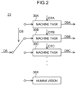
- FIG. 2 is a diagram showing a simplified configuration of the task processing unit 23.
- the image usage on the image decoding device 20 side includes at least one machine task and human vision.
- the image usage includes a plurality of machine tasks 30A to 30C and human vision 30X.
- the setting unit 22 outputs setting information D7B of the parameter value used when the task processing unit 23 executes the machine task 30B.
- the task processing unit 23 executes the machine task 30B by using the parameter value indicated in the setting information D7B based on the image data D5 and outputs result data D9B such as inference results.
- FIG. 3 is a diagram showing object detection and object segmentation as one example of the machine task.
- object detection the attribute of the object (television and person in this example) included in the input image is detected.
- the position and the number of objects in the input image may be detected.
- the position of the object to be recognized may be narrowed down, or objects other than the object to be recognized may be excluded.
- detection of a face in a camera and detection of a pedestrian or the like in autonomous driving can be considered.
- object segmentation pixels in the region corresponding to the object are segmented (or partitioned).
- usage such as separating obstacles and roads in autonomous driving to provide assistance to safe traveling of a car, detecting product defects in a factory, and identifying terrain in a satellite image can be considered.
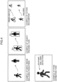
- FIG. 4 is a diagram showing object tracking, action recognition, and pose estimation as one example of the machine task.
- object tracking the movement of an object assigned with an identification number ID is tracked.
- counting the number of users in a shop or other facilities and analyzing motion of an athlete can be considered.
- Faster processing will enable real-time object tracking and application to camera processing such as autofocus.
- action recognition the type of action of the object (in this example, "riding a bicycle" and "walking") is detected.
- by the use for a security camera application to prevention and detection of criminal behavior such as robbery and shoplifting, and to prevention of forgetting work in a factory is possible.
- pose estimation the posture of the object is detected by keypoint and joint detection. For example, usage in an industrial field such as improving work efficiency in a factory, a security field such as detection of abnormal behavior, and healthcare and sports fields can be considered.
- FIG. 5 is a diagram showing a simplified configuration of the filter processing unit 11.
- the filter processing unit 11 includes a plurality of filters 40 of different types that can be selected according to the image usage on the image decoding device 20 side.
- the type includes at least one of the filter's shape, size, and coefficient value.
- the filter processing unit 11 includes filters 40A to 40C corresponding to the machine tasks 30A to 30C and a filter 40X corresponding to the human vision 30X.
- the usage information D8 selects, for example, the machine task 30B
- the usage information D2 selects the filter 40B corresponding to the machine task 30B.
- the filter processing unit 11 performs filter processing using the filter 40B on the input image to generate the first image and outputs image data D3B of the first image.
- the filters 40A to 40C corresponding to the machine tasks are filters that reduce the code amount of the first image from the code amount of the input image by the filter processing. As will be described later, the filters 40A to 40C may be filters that emphasize the important region indicating important features for the machine task while reducing the code amount of the non-important region, which is not important for the machine tasks.
- the filters 40A to 40C corresponding to the machine tasks include at least one of a noise removal filter, a sharpening filter, a bit depth conversion filter, a color space conversion filter, a resolution conversion filter, and a filter using a neural network.
- the noise removal filter includes at least one of a low-pass filter, a Gaussian filter, a smoothing filter, an averaging filter, a bilateral filter, and a median filter to remove noise by reducing information on details of the input image.
- the sharpening filter includes an edge detection filter or an edge enhancement filter, specifically includes a Laplacian filter, a Gaussian-Laplacian filter, a Sobel filter, a Prewitt filter, or a Canny edge detection filter.
- the bit depth conversion filter converts bit depth of luminance signals and/or color signals between the input image and the first image.
- the color space conversion filter converts the color space between the input image and the first image. For example, by converting the color space of YUV444 in the input image to YUV422, YUV420, or YUV400 in the first image, the code amount is reduced.
- the resolution conversion filter converts the image resolution between the input image and the first image.
- the resolution conversion filter includes a downsampling filter that reduces the resolution of the first image from the resolution of the input image.
- the resolution conversion filter may include an upsampling filter that increases the resolution of the first image from the resolution of the input image.
- the filters 40A to 40C corresponding to the machine tasks may include, for example, a deblocking filter, an ALF filter, a CCALF filter, an SAO filter, an LMCS filter, or an arbitrary combination thereof, as defined in H.266/versatile video codec (VVC).
- the filter 40X corresponding to the human vision is a filter that does not reduce the code amount of the first image from the code amount of the input image by filter processing.
- the filter 40X corresponding to the human vision includes a bypass filter that outputs the input image as it is as the first image.
- the filter 40X may be a filter that reduces the code amount of the first image from the code amount of the input image by filter processing, but the reduction effect of the code amount is suppressed more than the filters 40A to 40C.
- the filter 40X may be a filter that emphasizes the important region of the input image, but the emphasis effect is suppressed more than the filters 40A to 40C.
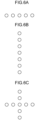
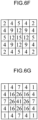
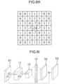
- FIGS. 6A to 6I are diagrams showing examples of a plurality of filters 40 of different types.
- FIGS. 6F and 6G show noise removal filters using a 5x5 Gaussian filter, with the filter in FIG. 6F having a relatively strong filter strength and the filter in FIG. 6G having a relatively weak filter strength.
- FIG. 6C shows
- FIG. 6H shows an edge detection filter using a 7 ⁇ 7 Gaussian-Laplacian filter.
- the plurality of filters 40 of different types may have different filter shapes, different filter sizes, and different filter coefficient values.
- FIG. 6I shows a filter using a neural network.
- the neural network has a convolution layer L1, a pooling layer L2, and a fully connected layer L3.
- the image data of the convolution layer L1 is generated by applying the convolution filter F1 to the image data D1 of the input image
- the image data of the pooling layer L2 is generated by applying the pooling filter F2 to the image data of the convolution layer L1.
- Image data D0 of the predicted residual is output from the fully connected layer L3, and the image data D1 and the image data D0 are added to output the image data D3 of the first image.
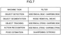
- FIG. 7 is a diagram showing an example of a lookup table that defines the filter selection based on the usage information D2.
- the lookup table is held by the filter processing unit 11.
- the filter processing unit 11 selects the weak noise removal filter and the weak sharpening filter because detailed information about the object is important.
- the filter processing unit 11 selects the weak noise removal filter because details of the image is important in the object segmentation model (Mask R-CNN) that performs prediction at the pixel level.
- the filter processing unit 11 selects the strong noise removal filter and the weak sharpening filter because detailed information about the object is not important.
- the filter processing unit 11 selects the strong noise removal filter and the strong sharpening filter to emphasize dynamic content such as an object edge while removing redundant information on static content such as background.
- the filter processing unit 11 selects the strong sharpening filter to emphasize details of the image because the pose estimation model (HRNet) learns high-resolution images to detect human keypoints such as ears or eyes.
- HRNet pose estimation model
- the filter processing unit 11 selects the strong noise removal filter for the machine task of object tracking and selects the weak noise removal filter for the machine task of object detection.
- the object detection is a process of detecting a target object in an image
- object tracking is a process of tracking a trajectory of an object in consecutive frames of a video.
- the object's edge and shape are essential, while in object detection, detailed information about the object is essential. Therefore, in object tracking, the strong noise removal filter is applied to remove detailed information, while in object detection, the weak noise removal filter is applied to remove only unnecessary information.
- the filter processing unit 11 selects the large size noise removal filter for the machine task of object tracking and selects the small size noise removal filter for the machine task of object detection.
- the small size noise removal filter removes noise over a wide range of frequency component because of low control performance for frequency component
- the large size noise removal filter can remove noise of a specific range of frequency component because of high control performance for frequency component.
- the small size filter has a less reduction effect on the code amount than the large size filter, while in other cases, the small size filter has a greater reduction effect on the code amount than the large size filter.
- the filter processing unit 11 selects a filter with a wide output color range and large bit depth for the machine task of object tracking, and selects a filter with a narrow output color range and small bit depth for the machine task of object detection. By applying the filter with a small bit depth, it is possible to enhance the reduction effect of code amount.
- the filter processing unit 11 selects different color space filters between the machine task of object tracking and the machine task of object detection.
- the filter processing unit 11 selects a downsampling filter with a small scale factor and high output resolution for the machine task of object tracking, and selects a downsampling filter with a large scale factor and low output resolution for the machine task of object detection.
- Each filter 40 shown in FIG. 5 may include one filter or a plurality of filters, or may include at least one filter and at least one image processing unit.
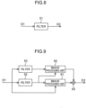
- FIG. 8 is a diagram showing a first configuration example of the filter 40.
- the filter 40 includes one filter 51.
- the filter 51 is, for example, a Gaussian filter.
- the filter 51 applies the Gaussian filter to the image data D1 to output the noise-removed image data D3.
- FIG. 9 is a diagram showing a second configuration example of the filter 40.
- the filter 40 includes two filters 52 and 53, two image processing units 61 and 62, and an addition processing unit 63.
- the filter 52 is, for example, a Gaussian-Laplacian filter
- the filter 53 is, for example, a Gaussian filter
- the image processing unit 61 is, for example, an edge extraction processing unit
- the image processing unit 62 is, for example, a background extraction processing unit.
- the filter 52 applies the Gaussian-Laplacian filter to the image data D1 of the input image to output an edge map showing the position of edge in the image.
- the filter 53 applies the Gaussian filter to the image data D1 of the input image to output noise-removed image data.
- the image processing unit 61 outputs an edge image by extracting the edge from the input image based on the image data D1 and the edge map.
- the image processing unit 62 outputs the background image by extracting the background from the input image based on the noise-removed image data and the edge map.
- the addition processing unit 63 outputs the image data D3 of the first image by adding the edge image and the background image.
- the filter processing unit 11 reduces the code amount of the first image from the code amount of the input image by defining the background region in the input image as the non-important region that is not important for the machine task, and deleting information on details of the background region (that is, high frequency range) by the filter 53.
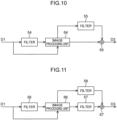
- FIG. 10 is a diagram showing a third configuration example of the filter 40.
- the filter 40 includes two filters 54 and 55, one image processing unit 64, and an addition processing unit 65.
- the filter 54 is, for example, a face detection filter using a neural network
- the filter 55 is, for example, an averaging filter
- the image processing unit 64 is, for example, a region division processing unit.
- the filter 54 detects the face of a person included in the image data D1 of the input image, and outputs a bounding box of the face that defines the position coordinates of the face.
- the image processing unit 64 separates the input image into a non-face region and a face region based on the image data D1 and the face bounding box.
- the filter 55 outputs a blurred face image by performing averaging on the face region.
- the addition processing unit 65 outputs the image data D3 of the first image by adding the image of the region other than the face and the blurred face image. For example, since details of the face are not important for the machine task of object tracking, by blurring the face, the code amount can be reduced and the privacy can be protected.
- the filter processing unit 11 reduces the code amount of the first image from the code amount of the input image by defining the face region in the input image as the non-important region that is not important for the machine task, and deleting information on details of the face region (that is, high frequency range) by the filter 55.
- FIG. 11 is a diagram showing a fourth configuration example of the filter 40.
- the filter 40 includes three filters 56 to 58, one image processing unit 66, and an addition processing unit 67.
- the filter 56 is, for example, a foreground detection filter using a neural network
- the filter 57 is, for example, a sharpening filter
- the filter 58 is, for example, a noise removal filter
- the image processing unit 66 is, for example, a region division processing unit.
- the filter 56 detects the foreground corresponding to an important subject included in the image data D1 of the input image, and outputs a bounding box of the foreground that defines the position coordinates of the foreground.
- the image processing unit 66 separates the input image into a foreground region and other background regions based on the image data D1 and the foreground bounding box.
- the filter 57 outputs the foreground image that has been sharpened by edge enhancement and the like by performing sharpening on the foreground region.
- the filter 58 outputs the noise-removed background image by performing noise removal processing on the background region.
- the addition processing unit 67 outputs the image data D3 of the first image by adding the sharpened foreground image and the noise-removed background image. In the example of FIG.
- the filter processing unit 11 reduces the code amount of the first image from the code amount of the input image by defining the background region in the input image as the non-important region that is not important for the machine task, and deleting information on details of the background region (that is, high frequency range) by the filter 58. Additionally, in the example of FIG. 11 , the filter processing unit 11 defines the foreground region as an important region that shows important features for the machine task in the input image, and emphasizes the foreground region by the filter 57 to improve the accuracy of the machine task such as action recognition or pose estimation.
- FIG. 12 is a diagram showing a first example of the data structure of the bit stream D4.
- the bit stream D4 includes a header H in which management information or the like is stored and a payload P in which image data is stored.
- the encoding processing unit 12 stores the encoded data 70 of the filter information D6 indicating the filter applied by the image encoding device 10 to the input image according to the machine task at a predetermined location of the payload P.
- FIG. 13 is a diagram showing a second example of the data structure of the bit stream D4.
- the bit stream D4 includes the header H and the payload P.
- the encoding processing unit 12 stores the encoded data 70 of the filter information D6 at a predetermined location of the header H.
- the predetermined location is, for example, the supplemental enhancement information (SEI) region for storing additional information.
- SEI Supplemental Enhancement information
- the predetermined location may be VPS, SPS, PPS, PH, SH, APS, a tile header, or the like.
- FIG. 14 is a diagram showing a first example of SEI message syntax about the filter information D6.
- prefilter_type_idc designates, for example, the type of filter by using three-bit flag information.
- prefilter_type_idc represents the noise removal filter when the value is "0”
- filter_strength_level_idc designates, for example, the filter strength by using three-bit flag information.
- filter_strength_level_idc represents the weakest filter strength when the value is "0", and represents stronger filter strength as the value increases.
- the maximum value of the filter strength is "7" or an arbitrary integer.
- input_bit_depth_minus8 designates, for example, the bit depth of the input image before applying filter processing using three-bit flag information.
- the bit depth of the input image is either "8", “10", “12”, or an arbitrary integer.
- input_color_format_idc designates, for example, the color space of the input image before applying filter processing using three-bit flag information.
- the color space that can be designated is monochrome, YUV444, YUV422, YUV420, YUV400, or an arbitrary color space.
- scale_factor designates the ratio between the resolution of the input image and the resolution of the first image. For example, when the resolution of the input image is 1920 x 1080 and the resolution of the first image is 960 x 540, the resolution in both vertical and horizontal directions becomes 1/2. Therefore, scale_factor_nominator is "1" and scale_factor_denominator is "2". scale_factor_nominator and scale_factor_denominator are each, for example, three-bit flag information, and can designate an arbitrary integer.
- FIG. 15 is a diagram showing a second example of SEI message syntax about the filter information D6.
- prefilter_hint_size_y designates the vertical size of the filter coefficient or correlation array, and is an arbitrary integer from “1" to "15”, for example.
- prefilter_hint_size_x designates the horizontal size of the filter coefficient or correlation array, and is an arbitrary integer from “1" to "15”, for example.
- prefilter_hint_type designates, for example, the type of filter by using two-bit flag information.
- prefilter_hint_type represents a two-dimensional FIR filter when the value is "0”
- prefilter_hint_type represents two one-dimensional FIR filters when the value is "1”
- prefilter_hint_value designates the filter coefficient or elements of the cross-correlation matrix.
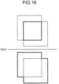
- FIG. 16 is a diagram for describing an example where the setting unit 22 sets a threshold for IOU as a parameter value used when executing the machine task.
- IOU is a value used to represent the degree of overlap between the predicted bounding box and the true bounding box in object detection.
- the predicted bounding box is shown with a broken line
- the true bounding box is shown with a dot-dash line.
- IOU is calculated as the ratio of the area of the region containing both bounding boxes (numerator) to the area of the region containing at least one bounding box (denominator).
- the threshold for IOU is set close to "1"
- the detection result becomes "true” only when the two bounding boxes almost overlap.
- the setting unit 22 extracts the filter information D6 from the bit stream D4, sets the threshold for IOU based on the filter information D6, and inputs the setting information D7 to the task processing unit 23.
- the task processing unit 23 executes the machine task by using the threshold for IOU indicated in the setting information D7.
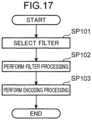
- FIG. 17 is a flowchart showing the process flow executed by the image encoding device 10.
- step SP101 the filter processing unit 11 selects one filter from the plurality of filters based on the usage information D2.
- step SP102 the filter processing unit 11 applies the filter selected in step SP101 to the input image and performs filter processing to generate the first image.
- step SP103 the encoding processing unit 12 performs encoding processing on the first image to generate the bit stream.
- the encoding processing unit 12 encodes the filter information D6 indicating the filter applied by the filter processing unit 11 to the input image and stores the encoded data 70 of the filter information D6 in the bit stream D4.
- the encoding processing unit 12 transmits the generated bit stream D4 to the image decoding device 20 via the network Nw.
- FIG. 18 is a flowchart showing the process flow executed by the image decoding device 20.
- step SP201 the decoding processing unit 21 receives the bit stream D4 from the image encoding device 10 via the network Nw and generates the decoded image by decoding the bit stream D4.
- step SP202 the setting unit 22 extracts the filter information D6 from the decoded bit stream D4, and sets the parameter value used when the task processing unit 23 executes the machine task based on the filter information D6.
- step SP203 the task processing unit 23 executes the machine task by using the decoded image decoded in step SP201 and the parameter value set in step SP202, and outputs the result data D9 such as inference results.
- the filter processing unit 11 includes a plurality of filters of different types, and selects one filter from the plurality of filters and applies the selected filter to the input image based on the usage information indicating the image usage on the image decoding device 20 side.
- the filter processing unit 11 can apply an appropriate filter to the input image based on the image usage on the image decoding device 20 side.
- noise removal filter by applying at least one of the low-pass filter, Gaussian filter, smoothing filter, averaging filter, bilateral filter, and median filter to the input image, it is possible to remove noise from the input image.
- bit efficiency in the transmission of the bit stream D4 from the image encoding device 10 to the image decoding device 20 it is possible to improve the bit efficiency in the transmission of the bit stream D4 from the image encoding device 10 to the image decoding device 20 by applying the filter that reduces the code amount when the image usage is the machine task.
- the filter processing unit 11 emphasizes the important region by the filter processing, making it possible to execute the machine task appropriately on the image decoding device 20 side.
- the image usage is the human vision
- the filter information D6 in the machine task on the image decoding device 20 side by storing the filter information D6 about the filter applied to the input image in the bit stream D4.
- the image decoding device 20 can easily extract the filter information D6 from the bit stream D4.
- the filter information D6 by storing the filter information D6 in the SEI region, it is possible to easily handle the filter information D6 as additional information.
- the setting unit 22 extracts the filter information D6 from the bit stream D4, and sets the parameter value used when the task processing unit 23 executes the machine task based on the filter information D6.
- the task processing unit 23 can execute appropriate task processing according to the filter applied by the image encoding device 10 to the input image.
- the present disclosure is particularly useful for application to the image processing system including the image encoding device that transmits images and the image decoding device that receives images.
Landscapes
- Engineering & Computer Science (AREA)
- Multimedia (AREA)
- Signal Processing (AREA)
- Physics & Mathematics (AREA)
- General Physics & Mathematics (AREA)
- Theoretical Computer Science (AREA)
- Image Processing (AREA)
- Compression Or Coding Systems Of Tv Signals (AREA)
Applications Claiming Priority (2)
| Application Number | Priority Date | Filing Date | Title |
|---|---|---|---|
| US202263325925P | 2022-03-31 | 2022-03-31 | |
| PCT/JP2023/011563 WO2023190053A1 (fr) | 2022-03-31 | 2023-03-23 | Dispositif de codage d'image, dispositif de décodage d'image, procédé de codage d'image et procédé de décodage d'image |
Publications (2)
| Publication Number | Publication Date |
|---|---|
| EP4485923A1 true EP4485923A1 (fr) | 2025-01-01 |
| EP4485923A4 EP4485923A4 (fr) | 2025-04-23 |
Family
ID=88202166
Family Applications (1)
| Application Number | Title | Priority Date | Filing Date |
|---|---|---|---|
| EP23780064.4A Pending EP4485923A4 (fr) | 2022-03-31 | 2023-03-23 | Dispositif de codage d'image, dispositif de décodage d'image, procédé de codage d'image et procédé de décodage d'image |
Country Status (4)
| Country | Link |
|---|---|
| US (1) | US20250024033A1 (fr) |
| EP (1) | EP4485923A4 (fr) |
| CN (1) | CN118947114A (fr) |
| WO (1) | WO2023190053A1 (fr) |
Families Citing this family (1)
| Publication number | Priority date | Publication date | Assignee | Title |
|---|---|---|---|---|
| CN120499379B (zh) * | 2025-07-04 | 2026-04-10 | 摩尔线程智能科技(北京)股份有限公司 | 一种视频编码预处理方法及装置、电子设备、存储介质和计算机程序产品 |
Family Cites Families (8)
| Publication number | Priority date | Publication date | Assignee | Title |
|---|---|---|---|---|
| JP2611598B2 (ja) * | 1992-03-20 | 1997-05-21 | 日本ビクター株式会社 | 画像圧縮装置 |
| KR101773012B1 (ko) | 2009-12-31 | 2017-08-30 | 톰슨 라이센싱 | 비디오 인코딩 및 디코딩을 위해 적응형 결합된 전처리 및 후처리 필터들을 위한 방법들 및 장치 |
| KR20120118779A (ko) * | 2011-04-19 | 2012-10-29 | 삼성전자주식회사 | 전처리 필터링을 수반한 계층 간 예측을 수행하는 비디오 부호화 방법 및 그 장치, 후처리 필터링을 수반한 계층 간 예측을 수행하는 비디오 복호화 방법 및 그 장치 |
| US10205953B2 (en) * | 2012-01-26 | 2019-02-12 | Apple Inc. | Object detection informed encoding |
| JP7224280B6 (ja) * | 2016-10-04 | 2026-02-17 | ビー1、インスティテュート、オブ、イメージ、テクノロジー、インコーポレイテッド | 画像データ符号化/復号化方法及び装置 |
| US10452955B2 (en) | 2018-01-15 | 2019-10-22 | Gyrfalcon Technology Inc. | System and method for encoding data in an image/video recognition integrated circuit solution |
| EP3941057A4 (fr) * | 2019-03-24 | 2022-06-01 | Guangdong Oppo Mobile Telecommunications Corp., Ltd. | Procédé et dispositif de filtrage, encodeur et support de stockage informatique |
| WO2021172956A1 (fr) * | 2020-02-28 | 2021-09-02 | 엘지전자 주식회사 | Procédé et appareil de codage/décodage d'image pour la signalisation d'informations de caractéristique d'image, et procédé de transmission de flux binaire |
-
2023
- 2023-03-23 WO PCT/JP2023/011563 patent/WO2023190053A1/fr not_active Ceased
- 2023-03-23 EP EP23780064.4A patent/EP4485923A4/fr active Pending
- 2023-03-23 CN CN202380031418.6A patent/CN118947114A/zh active Pending
-
2024
- 2024-09-27 US US18/899,188 patent/US20250024033A1/en active Pending
Also Published As
| Publication number | Publication date |
|---|---|
| WO2023190053A1 (fr) | 2023-10-05 |
| EP4485923A4 (fr) | 2025-04-23 |
| CN118947114A (zh) | 2024-11-12 |
| US20250024033A1 (en) | 2025-01-16 |
Similar Documents
| Publication | Publication Date | Title |
|---|---|---|
| EP3291558B1 (fr) | Procédés et appareil de codage et décodage de vidéo | |
| US10552962B2 (en) | Fast motion based and color assisted segmentation of video into region layers | |
| CN113660486B (zh) | 图像编码、解码、重建、分析方法、系统及电子设备 | |
| CN110503609B (zh) | 一种基于混合感知模型的图像去雨方法 | |
| CN110536138B (zh) | 一种有损压缩编码方法、装置和系统级芯片 | |
| US20250024033A1 (en) | Image encoding device, image decoding device, image encoding method, and image decoding method | |
| US20210248757A1 (en) | Method of detecting moving objects via a moving camera, and related processing system, device and computer-program product | |
| CN115035172A (zh) | 基于置信度分级及级间融合增强的深度估计方法及系统 | |
| JP2025183340A (ja) | 画像処理方法 | |
| EP4510569A1 (fr) | Dispositif de codage d'images, dispositif de décodage d'images, procédé de codage d'images et procédé de décodage d'images | |
| EP4521748A1 (fr) | Dispositif de codage d'image, dispositif de décodage d'image, procédé de codage d'image et procédé de décodage d'image | |
| WO2025020143A1 (fr) | Système et procédé de super-résolution de profondeur guidée par le bord par fusion multimodale hiérarchique basée sur l'attention | |
| CN105791687A (zh) | 一种蛙眼仿生检测方法及蛙眼仿生摄像机 | |
| Shree et al. | Image restoration and object detection in unfavourable weather conditions for autonomous vehicles using deep learning approaches: a review | |
| JP7704842B2 (ja) | 画像符号化方法、画像復号方法、画像処理方法、画像符号化装置、及び画像復号装置 | |
| CN117690049B (zh) | 演化和继承的高分辨率无人机图像显著性目标检测方法 | |
| Lan et al. | Latent Edge Guided Depth Super-Resolution Using Attention-Based Hierarchical Multi-Modal Fusion | |
| KR20240175892A (ko) | 비디오 데이터의 전경과 배경을 가변적으로 결정하는 기술 | |
| Banerjee et al. | A Joint Intensity-Neuromorphic Event Imaging System for Resource Constrained Devices | |
| Sharma et al. | Open Set Pedestrian Re Identification through Uncertainty Calibrated Vision Language Similarity | |
| Aguiar et al. | MBIE: Motion-Blurred Image Enhancement for Mobile Robots | |
| HK40064484B (zh) | 图像编码、解码、重建、分析方法、系统及电子设备 | |
| Nakamura et al. | Improvement of DeblurGAN for Low-Quality QR Codes | |
| AU2024250863A1 (en) | Decoder, encoder, decoding method, and encoding method | |
| WO2025120331A1 (fr) | Perfectionnements et intégration de codage d'amélioration |
Legal Events
| Date | Code | Title | Description |
|---|---|---|---|
| STAA | Information on the status of an ep patent application or granted ep patent |
Free format text: STATUS: THE INTERNATIONAL PUBLICATION HAS BEEN MADE |
|
| PUAI | Public reference made under article 153(3) epc to a published international application that has entered the european phase |
Free format text: ORIGINAL CODE: 0009012 |
|
| STAA | Information on the status of an ep patent application or granted ep patent |
Free format text: STATUS: REQUEST FOR EXAMINATION WAS MADE |
|
| 17P | Request for examination filed |
Effective date: 20240925 |
|
| AK | Designated contracting states |
Kind code of ref document: A1 Designated state(s): AL AT BE BG CH CY CZ DE DK EE ES FI FR GB GR HR HU IE IS IT LI LT LU LV MC ME MK MT NL NO PL PT RO RS SE SI SK SM TR |
|
| A4 | Supplementary search report drawn up and despatched |
Effective date: 20250324 |
|
| RIC1 | Information provided on ipc code assigned before grant |
Ipc: H04N 19/82 20140101ALI20250318BHEP Ipc: H04N 19/80 20140101ALI20250318BHEP Ipc: H04N 19/70 20140101ALI20250318BHEP Ipc: H04N 19/17 20140101ALI20250318BHEP Ipc: H04N 19/132 20140101ALI20250318BHEP Ipc: H04N 19/117 20140101AFI20250318BHEP |
|
| DAV | Request for validation of the european patent (deleted) | ||
| DAX | Request for extension of the european patent (deleted) |