EP4485932A1 - Procédé et appareil de codage, support de stockage et produit-programme d'ordinateur - Google Patents
Procédé et appareil de codage, support de stockage et produit-programme d'ordinateur Download PDFInfo
- Publication number
- EP4485932A1 EP4485932A1 EP23777684.4A EP23777684A EP4485932A1 EP 4485932 A1 EP4485932 A1 EP 4485932A1 EP 23777684 A EP23777684 A EP 23777684A EP 4485932 A1 EP4485932 A1 EP 4485932A1
- Authority
- EP
- European Patent Office
- Prior art keywords
- feature
- motion
- residual
- image
- current
- Prior art date
- Legal status (The legal status is an assumption and is not a legal conclusion. Google has not performed a legal analysis and makes no representation as to the accuracy of the status listed.)
- Pending
Links
Images






Classifications
-
- H—ELECTRICITY
- H04—ELECTRIC COMMUNICATION TECHNIQUE
- H04N—PICTORIAL COMMUNICATION, e.g. TELEVISION
- H04N19/00—Methods or arrangements for coding, decoding, compressing or decompressing digital video signals
- H04N19/50—Methods or arrangements for coding, decoding, compressing or decompressing digital video signals using predictive coding
- H04N19/503—Methods or arrangements for coding, decoding, compressing or decompressing digital video signals using predictive coding involving temporal prediction
-
- H—ELECTRICITY
- H04—ELECTRIC COMMUNICATION TECHNIQUE
- H04N—PICTORIAL COMMUNICATION, e.g. TELEVISION
- H04N19/00—Methods or arrangements for coding, decoding, compressing or decompressing digital video signals
- H04N19/50—Methods or arrangements for coding, decoding, compressing or decompressing digital video signals using predictive coding
- H04N19/503—Methods or arrangements for coding, decoding, compressing or decompressing digital video signals using predictive coding involving temporal prediction
- H04N19/51—Motion estimation or motion compensation
-
- G—PHYSICS
- G06—COMPUTING OR CALCULATING; COUNTING
- G06N—COMPUTING ARRANGEMENTS BASED ON SPECIFIC COMPUTATIONAL MODELS
- G06N3/00—Computing arrangements based on biological models
- G06N3/02—Neural networks
- G06N3/04—Architecture, e.g. interconnection topology
- G06N3/045—Combinations of networks
-
- H—ELECTRICITY
- H04—ELECTRIC COMMUNICATION TECHNIQUE
- H04N—PICTORIAL COMMUNICATION, e.g. TELEVISION
- H04N19/00—Methods or arrangements for coding, decoding, compressing or decompressing digital video signals
- H04N19/10—Methods or arrangements for coding, decoding, compressing or decompressing digital video signals using adaptive coding
- H04N19/134—Methods or arrangements for coding, decoding, compressing or decompressing digital video signals using adaptive coding characterised by the element, parameter or criterion affecting or controlling the adaptive coding
- H04N19/136—Incoming video signal characteristics or properties
-
- H—ELECTRICITY
- H04—ELECTRIC COMMUNICATION TECHNIQUE
- H04N—PICTORIAL COMMUNICATION, e.g. TELEVISION
- H04N19/00—Methods or arrangements for coding, decoding, compressing or decompressing digital video signals
- H04N19/10—Methods or arrangements for coding, decoding, compressing or decompressing digital video signals using adaptive coding
- H04N19/134—Methods or arrangements for coding, decoding, compressing or decompressing digital video signals using adaptive coding characterised by the element, parameter or criterion affecting or controlling the adaptive coding
- H04N19/136—Incoming video signal characteristics or properties
- H04N19/137—Motion inside a coding unit, e.g. average field, frame or block difference
-
- H—ELECTRICITY
- H04—ELECTRIC COMMUNICATION TECHNIQUE
- H04N—PICTORIAL COMMUNICATION, e.g. TELEVISION
- H04N19/00—Methods or arrangements for coding, decoding, compressing or decompressing digital video signals
- H04N19/10—Methods or arrangements for coding, decoding, compressing or decompressing digital video signals using adaptive coding
- H04N19/169—Methods or arrangements for coding, decoding, compressing or decompressing digital video signals using adaptive coding characterised by the coding unit, i.e. the structural portion or semantic portion of the video signal being the object or the subject of the adaptive coding
- H04N19/17—Methods or arrangements for coding, decoding, compressing or decompressing digital video signals using adaptive coding characterised by the coding unit, i.e. the structural portion or semantic portion of the video signal being the object or the subject of the adaptive coding the unit being an image region, e.g. an object
- H04N19/172—Methods or arrangements for coding, decoding, compressing or decompressing digital video signals using adaptive coding characterised by the coding unit, i.e. the structural portion or semantic portion of the video signal being the object or the subject of the adaptive coding the unit being an image region, e.g. an object the region being a picture, frame or field
-
- H—ELECTRICITY
- H04—ELECTRIC COMMUNICATION TECHNIQUE
- H04N—PICTORIAL COMMUNICATION, e.g. TELEVISION
- H04N19/00—Methods or arrangements for coding, decoding, compressing or decompressing digital video signals
- H04N19/42—Methods or arrangements for coding, decoding, compressing or decompressing digital video signals characterised by implementation details or hardware specially adapted for video compression or decompression, e.g. dedicated software implementation
-
- H—ELECTRICITY
- H04—ELECTRIC COMMUNICATION TECHNIQUE
- H04N—PICTORIAL COMMUNICATION, e.g. TELEVISION
- H04N19/00—Methods or arrangements for coding, decoding, compressing or decompressing digital video signals
- H04N19/44—Decoders specially adapted therefor, e.g. video decoders which are asymmetric with respect to the encoder
-
- H—ELECTRICITY
- H04—ELECTRIC COMMUNICATION TECHNIQUE
- H04N—PICTORIAL COMMUNICATION, e.g. TELEVISION
- H04N19/00—Methods or arrangements for coding, decoding, compressing or decompressing digital video signals
- H04N19/50—Methods or arrangements for coding, decoding, compressing or decompressing digital video signals using predictive coding
- H04N19/503—Methods or arrangements for coding, decoding, compressing or decompressing digital video signals using predictive coding involving temporal prediction
- H04N19/51—Motion estimation or motion compensation
- H04N19/527—Global motion vector estimation
-
- H—ELECTRICITY
- H04—ELECTRIC COMMUNICATION TECHNIQUE
- H04N—PICTORIAL COMMUNICATION, e.g. TELEVISION
- H04N19/00—Methods or arrangements for coding, decoding, compressing or decompressing digital video signals
- H04N19/60—Methods or arrangements for coding, decoding, compressing or decompressing digital video signals using transform coding
- H04N19/61—Methods or arrangements for coding, decoding, compressing or decompressing digital video signals using transform coding in combination with predictive coding
-
- H—ELECTRICITY
- H04—ELECTRIC COMMUNICATION TECHNIQUE
- H04N—PICTORIAL COMMUNICATION, e.g. TELEVISION
- H04N19/00—Methods or arrangements for coding, decoding, compressing or decompressing digital video signals
- H04N19/90—Methods or arrangements for coding, decoding, compressing or decompressing digital video signals using coding techniques not provided for in groups H04N19/10-H04N19/85, e.g. fractals
- H04N19/91—Entropy coding, e.g. variable length coding [VLC] or arithmetic coding
-
- G—PHYSICS
- G06—COMPUTING OR CALCULATING; COUNTING
- G06N—COMPUTING ARRANGEMENTS BASED ON SPECIFIC COMPUTATIONAL MODELS
- G06N3/00—Computing arrangements based on biological models
- G06N3/02—Neural networks
- G06N3/08—Learning methods
Definitions
- This application relates to the field of data compression technologies, and in particular, to an encoding method and apparatus, a storage medium, and a computer program product.
- Video coding can reduce pressure of occupation of network bandwidth by video storage and video transmission.
- Video coding is also referred to as video compression.
- An essence of video coding is to remove redundant information from a video, to use less data (video bitstream) to represent an original video.
- Video coding includes intra prediction coding and inter prediction coding. Intra prediction coding does not need to use a reference frame, and inter prediction coding needs to use a current frame and a reference frame to determine inter motion information, and use the inter motion information to compress a video.
- a key of video coding is how to use the inter motion information more effectively. Therefore, current researches related to video coding increasingly focus on inter prediction coding. However, in some current inter prediction coding schemes, prediction accuracy of inter motion information is low.
- Embodiments of this application provide an encoding method and apparatus, a storage medium, and a computer program product, to improve prediction accuracy of inter motion information and further improve compression performance.
- the technical solutions are as follows.
- an encoding method includes: determining a current feature and a reference feature, where the current feature is a feature of a to-be-encoded current image, and the reference feature is a feature of a reference image of the current image; determining a correlation matrix of the reference feature relative to the current feature; determining an inter motion feature based on the correlation matrix; and encoding the inter motion feature into a bitstream.
- the correlation matrix is introduced to fit inter motion. Because the correlation matrix can represent a part with strong correlation and a part with weak correlation between the current feature and the reference feature, and inter motion information corresponding to the part with strong correlation is richer, in a process of fitting the inter motion, inter motion corresponding to the part with strong correlation can be better fitted based on a size of each element in the correlation matrix, and less attention is paid to inter motion corresponding to the part with weak correlation.
- the correlation matrix has an information enhancement function for prediction of the inter motion feature, and can improve prediction accuracy of the inter motion feature and further improve compression performance.
- the determining an inter motion feature based on the correlation matrix includes: inputting the correlation matrix into a motion encoding network to obtain the inter motion feature; or inputting the correlation matrix, the current feature, and the reference feature into a motion encoding network to obtain the inter motion feature; or inputting the correlation matrix, the current image, and the reference image into a motion encoding network to obtain the inter motion feature.
- an encoder side may directly input the correlation matrix into the motion encoding network to obtain the inter motion feature, or may obtain the inter motion feature by using the reference feature and the current feature of feature space in combination with the correlation matrix, or may obtain the inter motion feature by using the reference image and the current image of image space in combination with the correlation matrix.
- the determining an inter motion feature based on the correlation matrix includes: using the reference feature as a predicted feature, and inputting the correlation matrix, the predicted feature, and the current feature into a motion encoding network to obtain a motion feature; and determining a quantity of iterations; if the quantity of iterations is less than an iteration quantity threshold, inputting the motion feature into a motion decoding network to obtain a reconstructed motion feature, transforming the reference feature based on the reconstructed motion feature to re-determine the predicted feature, re-determining a correlation matrix of the predicted feature relative to the current feature, and returning to perform the step of inputting the correlation matrix, the predicted feature, and the current feature into the motion encoding network to obtain the motion feature; and if the quantity of iterations is equal to the iteration quantity threshold, determining the motion feature as the inter motion feature.
- the method further includes: determining a residual feature based on the inter motion feature; and encoding the residual feature into the bitstream.
- the encoder side further determines the residual feature and encodes the residual feature, so that the decoder side decompresses a video based on the inter motion feature and the residual feature.
- the determining a residual feature based on the inter motion feature includes: inputting the inter motion feature into the motion decoding network to obtain the reconstructed motion feature between the current image and the reference image; transforming the reference image based on the reconstructed motion feature between the current image and the reference image to obtain a predicted image; determining a second residual, where the second residual is a residual between the predicted image and the current image; and inputting the second residual into a residual encoding network to obtain the residual feature.
- the encoder side performs transformation and prediction in the image space.
- the third determining module is configured to:
- the third determining module is configured to:
- the apparatus further includes:
- the fourth determining module is configured to:
- the reference image is a reconstructed image of a reference frame.
- an encoding apparatus includes a processor and an interface circuit.
- the processor receives and/or sends data by using the interface circuit, and the processor is configured to invoke program instructions stored in a memory, to perform the encoding method provided in the first aspect.
- the encoding apparatus includes the memory.
- the processor is configured to determine a current feature and a reference feature, where the current feature is a feature of a to-be-encoded current image, and the reference feature is a feature of a reference image of the current image; and the processor is further configured to determine a correlation matrix of the reference feature relative to the current feature, determine an inter motion feature based on the correlation matrix, and encode the inter motion feature into a bitstream.
- a computer device includes a processor and a memory.
- the memory is configured to store a program for performing the encoding method provided in the first aspect, and store data used to implement the encoding method provided in the first aspect.
- the processor is configured to execute the program stored in the memory.
- the computer device may further include a communication bus, and the communication bus is configured to establish a connection between the processor and the memory.
- a computer program product including instructions is provided.
- the computer program product When the computer program product is run on a computer, the computer performs the encoding method according to the first aspect.
- a system architecture and a service scenario that are described in embodiments of this application are intended to describe technical solutions in embodiments of this application more clearly, and do not constitute a limitation on the technical solutions provided in embodiments of this application.
- a person of ordinary skill in the art may be aware that, with evolution of the system architecture and emergence of a new service scenario, the technical solutions provided in embodiments of this application are also applicable to similar technical problems.
- a pixel depth (bits per pixel, BPP) is also referred to as bit/pixel.
- BPP is a quantity of bits used to store each pixel.
- a smaller BPP indicates a smaller compression bit rate.
- Bit rate In image compression, a bit rate refers to an encoding length required for encoding a unit pixel. A higher bit rate indicates better image reconstruction quality.
- a peak signal-to-noise ratio (peak signal-to-noise ratio, PSNR) is an objective standard for evaluating image quality. A higher PSNR indicates better image quality.
- Multi-scale structural similarity index measure (multi-scale structural similarity index measure, MS-SSIM) is an objective standard for evaluating an image. A higher MS-SSIM indicates better image quality.
- Convolutional neural network (convolutional neural network, CNN) is a feedforward neural network that includes convolutional computing and has a deep structure and is one of representative algorithms of deep learning.
- Group of pictures A bitstream of a video includes a plurality of GOPs.
- a GOP is a group of continuous pictures, includes an I frame, a P frame, and/or a B frame, and is a basic unit for a video image encoder and a video image decoder to access.
- An I frame is an intra-coded (intra-coded) frame, and is also referred to as a key frame.
- the I frame is compressed and generated without referring to other pictures.
- the I frame describes details of an image background and a motion subject. During decoding, a complete image can be reconstructed using only data of the I frame.
- the I frame is generally a first frame of each GOP and is used as a reference frame for random access.
- a P frame is a forward predictive-coded (predictive-coded) frame, and is also referred to as a forward prediction frame (a forward reference frame).
- the P frame indicates a difference between this frame and a previous key frame (or P frame).
- the P frame transmits, by using a motion compensation method, a prediction error and a motion vector between the P frame and a previous I frame or P frame.
- a difference represented by this frame needs to be superposed on a previously buffered picture to generate a complete image.
- a B frame is a bidirectionally predicted (bidirectionally predicted) frame, and is also referred to as a bidirectional interpolation frame or bidirectional reference frame.
- the B frame uses a previous I frame or P frame and a subsequent P frame as reference frames.
- the B frame transmits a prediction error and a motion vector between the B frame and two adjacent reference frames. During decoding, based on the motion vector and the prediction error, two adjacent reference frames are combined to obtain a complete image.
- the I frame uses intra prediction coding
- the P frame and B frame use inter prediction coding.
- the P frame and the B frame have a higher compression ratio.
- Inter prediction coding mainly includes two parts. One part is an inter prediction part, and the other part is a residual compression part.
- the inter prediction part includes a prediction and compression module of inter side information and a transformation module.
- the inter side information is reflected as an optical flow.
- images of a reference frame and a current frame are input into an optical flow estimation network, to obtain a predicted optical flow and compress the optical flow.
- the inter side information is reflected as a motion feature.
- image features of a current frame and a reference frame are extracted, and the image features of the current frame and the reference frame are input into a convolutional neural network, to obtain a predicted motion feature and compress the motion feature.
- the transformation module usually performs a wrap operation, and in an encoding process, transforms a reference frame into a prediction result of a current frame by using inter side information.
- Correlation matrix In this embodiment of this application, a correlation matrix of a reference feature relative to a current feature is determined, so that a more accurate inter motion feature is predicted by using the correlation matrix.
- the correlation matrix is also referred to as a cross-correlation matrix, a neighboring cross-correlation matrix, a neighboring correlation matrix, or the like.
- a calculation manner for determining a correlation matrix of one feature relative to another feature includes: giving two features F1 and F2 and a neighboring size, and calculating a neighboring correlation matrix of the feature F2 relative to the feature F1.
- the neighboring size is k*k
- dimensions of the feature F1 and the feature F2 both are c * h * w , where c , h, and w are respectively a quantity of channels, a height, and a width of the feature space, and h * w represents a size of the feature space.
- An operation of calculating the neighboring correlation matrix includes: donating a feature vector of a point ( i , j ) of the feature F1 as f i , j 1 , where i ⁇ [1, h ] , and j ⁇ [1, w ].
- a correlation value corr f x , y 2 f i , j 1 between a feature vector f x , y 2 of all points in a neighboring range, in the feature F2, that uses a point ( i , j ) as a center and that has a size of k*k and f i , j 1 is calculated.
- a corr() function may be a distance function in any form, for example, a function such as an inner product function, a cosine (cos) function, an L1 distance function, or an L2 distance function, or a distance function obtained through convolutional learning.
- FIG. 1 is a diagram of an implementation environment according to an embodiment of this application.
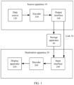
- the implementation environment includes a source apparatus 10, a destination apparatus 20, a link 30, and a storage apparatus 40.
- the source apparatus 10 may generate an encoded video, that is, a bitstream. Therefore, the source apparatus 10 may also be referred to as an encoding apparatus.
- the destination apparatus 20 may decode the bitstream generated by the source apparatus 10. Therefore, the destination apparatus 20 may also be referred to as a decoding apparatus.
- the link 30 may receive the encoded video generated by the source apparatus 10, and may transmit the encoded video to the destination apparatus 20.
- the storage apparatus 40 may receive the encoded video generated by the source apparatus 10, and may store the encoded video. In this case, the destination apparatus 20 may directly obtain the encoded video from the storage apparatus 40.
- the storage apparatus 40 may correspond to a file server or another intermediate storage apparatus that may store the encoded video generated by the source apparatus 10. In this case, the destination apparatus 20 may transmit, in a streaming manner, or download the encoded video
- the source apparatus 10 and the destination apparatus 20 each may include one or more processors and a memory coupled to the one or more processors.
- the memory may include a random access memory (random access memory, RAM), a read-only memory (read-only memory, ROM), an electrically erasable programmable read-only memory (electrically erasable programmable read-only memory, EEPROM), a flash memory, any other medium that can be configured to store required program encode in a form of instructions or data structures accessible to a computer, or the like.
- the source apparatus 10 and the destination apparatus 20 may both include a mobile phone, a smartphone, a personal digital assistant (personal digital assistant, PDA), a wearable device, a pocket PC (pocket PC, PPC), a tablet computer, a smart in-vehicle infotainment, a smart television, a smart sound box, a desktop computer, a mobile computing apparatus, a notebook (for example, a laptop) computer, a tablet computer, a set-top box, a telephone handheld such as a so-called "smart" phone, a television, a camera, a display apparatus, a digital media player, a video game console, a vehicle-mounted computer, or the like.
- PDA personal digital assistant
- PPC pocket PC
- tablet computer a smart in-vehicle infotainment
- smart television a smart sound box
- desktop computer a mobile computing apparatus
- a notebook (for example, a laptop) computer a tablet computer
- a set-top box a telephone handheld such as
- the link 30 may include one or more media or apparatuses that can transmit the encoded video from the source apparatus 10 to the destination apparatus 20.
- the link 30 may include one or more communication media that can enable the source apparatus 10 to directly send the encoded video to the destination apparatus 20 in real time.
- the source apparatus 10 may modulate the encoded video according to a communication standard, where the communication standard may be a wireless communication protocol or the like; and may send a modulated video to the destination apparatus 20.
- the one or more communication media may include a wireless communication medium and/or a wired communication medium.
- the one or more communication media may include a radio frequency (radio frequency, RF) spectrum or one or more physical transmission lines.
- the storage apparatus 40 may store a received encoded video sent by the source apparatus 10, and the destination apparatus 20 may directly obtain the encoded video from the storage apparatus 40.
- the storage apparatus 40 may include any one of a plurality of distributed or locally accessed data storage media.
- the any one of a plurality of distributed or locally accessed data storage media may be a hard disk drive, a Blu-ray disc, a digital versatile disc (digital versatile disc, DVD), a compact disc read-only memory (compact disc read-only memory, CD-ROM), a flash memory, a volatile or non-volatile memory, or any other appropriate digital storage medium configured to store a bitstream.
- the storage apparatus 40 may correspond to a file server or another intermediate storage apparatus that may store a bitstream generated by the source apparatus 10, and the destination apparatus 20 may transmit, in a streaming manner, or download the bitstream stored in the storage apparatus 40.
- the file server may be any type of server that can store an encoded video and send the encoded video to the destination apparatus 20.
- the file server may include a network server, a file transfer protocol (file transfer protocol, FTP) server, a network attached storage (network attached storage, NAS) apparatus, a local disk drive, or the like.
- the destination apparatus 20 may obtain the encoded image through any standard data connection (including an Internet connection).
- the any standard data connection may include a wireless channel (for example, a Wi-Fi connection), a wired connection (for example, a digital subscriber line (digital subscriber line, DSL) or a cable modem), or a combination of a wireless channel and a wired connection that are suitable for obtaining the encoded video stored on the file server.
- Transmission of the encoded video from the storage apparatus 40 may be streaming transmission, transmission in a download manner, or a combination thereof.
- FIG. 1 The implementation environment shown in FIG. 1 is merely a possible implementation.
- technologies in embodiments of this application are not only applicable to the source apparatus 10 that may encode an image and the destination apparatus 20 that may decode an encoded video in FIG. 1 , but also applicable to another apparatus that may encode a video and decode a bitstream. This is not specifically limited in embodiments of this application.
- the source apparatus 10 includes a data source 120, an encoder 100, and an output interface 140.
- the output interface 140 may include a modulator/demodulator (modem) and/or a sender.
- the sender may also be referred to as a transmitter.
- the data source 120 may include a video capture apparatus (for example, a camera), an archive containing a previously captured video, a feed interface for receiving a video from a video content provider, and/or a computer graphics system for generating a video, or a combination of these sources of video.
- the data source 120 may send a video to the encoder 100.
- the encoder 100 may encode the received video sent by the data source 120, to obtain an encoded video.
- the encoder may send the encoded video to the output interface.
- the source apparatus 10 directly sends the encoded video to the destination apparatus 20 through the output interface 140.
- the encoded video may alternatively be stored in the storage apparatus 40 for the destination apparatus 20 to obtain subsequently for decoding and/or display.
- the destination apparatus 20 includes an input interface 240, a decoder 200, and a display apparatus 220.
- the input interface 240 includes a receiver and/or a modem.
- the input interface 240 may receive an encoded video via the link 30 and/or from the storage apparatus 40, and then send the encoded video to the decoder 200.
- the decoder 200 may decode the received encoded video to obtain a decoded video.
- the decoder may send the decoded video to the display apparatus 220.
- the display apparatus 220 may be integrated with the destination apparatus 20 or disposed outside the destination apparatus 20. Generally, the display apparatus 220 displays the decoded video.
- the display apparatus 220 may be a display apparatus of any one of a plurality of types.
- the display apparatus 220 may be a liquid crystal display (liquid crystal display, LCD), a plasma display, an organic light-emitting diode (organic light-emitting diode, OLED) display, or another type of display apparatus.
- LCD liquid crystal display
- OLED organic light-emitting diode
- the encoder 100 and the decoder 200 may be respectively integrated with an encoder and a decoder, and may include an appropriate multiplexer-demultiplexer (multiplexer-demultiplexer, MUX-DEMUX) unit or other hardware and software for encoding both audio and a video in a shared data stream or a separate data stream.
- MUX-DEMUX multiplexer-demultiplexer
- the MUX-DEMUX unit may comply with the ITU H.223 multiplexer protocol or another protocol such as a user datagram protocol (user datagram protocol, UDP).
- the encoder 100 and the decoder 200 each may be any one of the following circuits: one or more microprocessors, a digital signal processor (digital signal processor, DSP), an application-specific integrated circuit (application-specific integrated circuit, ASIC), a field-programmable gate array (field-programmable gate array, FPGA), discrete logic, hardware, or any combination thereof.
- DSP digital signal processor
- ASIC application-specific integrated circuit
- FPGA field-programmable gate array
- an apparatus may store, in an appropriate non-volatile computer-readable storage medium, instructions for the software, and may use one or more processors to execute instructions in hardware, to implement the technologies in embodiments of this application. Any one of the foregoing content (including hardware, software, a combination of hardware and software, and the like) may be considered as one or more processors.
- the encoder 100 and the decoder 200 each may be included in one or more encoders or decoders. Any one of the encoders or decoders may be integrated as a part of a combined encoder/decoder (codec) in a corresponding apparatus.
- codec encoder/decoder
- the encoder 100 may be generally referred to as "signaling” or “sending” some information to another apparatus, for example, the decoder 200.
- the term “signaling” or “sending” may generally indicate transmission of a syntax element and/or other data used to decode a compressed video. Such transmission may occur in real time or almost in real time. Alternatively, such communication may occur after a period of time, for example, may occur when a syntax element in an encoded bitstream is stored in a computer-readable storage medium during encoding, and then a decoding apparatus may retrieve the syntax element at any time after the syntax element is stored in the medium.
- FIG. 2 is a diagram of another implementation environment according to an embodiment of this application.
- the implementation environment includes an encoder side and a decoder side.
- the encoder side includes an AI encoding module, an entropy encoding module, and a file sending module.
- the decoder side includes a file loading module, an entropy decoding module, and an AI decoding module.
- the encoder side After obtaining a to-be-compressed video, the encoder side obtains, by using the AI encoding unit, an inter motion feature and a residual feature that are to be encoded, and performs entropy encoding on the inter motion feature and the residual feature, to obtain a bitstream, that is, a compressed file of the video.
- the encoder side saves the compressed file.
- the compressed file is transmitted to the decoder side, and the decoder side loads the compressed file, and obtains a decompressed video by using the entropy decoding unit and the AI decoding unit.
- the AI encoding unit includes one or more of an image feature extraction network, a motion encoding network, a residual encoding network, an entropy estimation network, a motion decoding network, a residual decoding network, or the like in the following.
- the AI decoding unit includes one or more of the motion decoding network, the residual decoding network, the entropy estimation network, or the like in the following.
- processes of processing data by the AI encoding unit and the AI decoding unit are implemented on an embedded neural network processing unit (neural network processing unit, NPU), to improve data processing efficiency.
- NPU neural network processing unit
- Processes such as entropy encoding, file saving, and loading are implemented on a central processing unit (central processing unit, CPU).
- the encoder side and the decoder side are one device, or the encoder side and the decoder side are two independent devices. That is, for one device, the device has both a video compression function and a video decompression function, or the device has a video compression function or a video decompression function.
- an encoding/decoding method provided in embodiments of this application may be applied to a plurality of scenarios, for example, service scenarios such as cloud storage, video surveillance, live broadcast, and transmission, and may be specifically applied to terminal video recording, a video album, cloud storage, and the like.
- service scenarios such as cloud storage, video surveillance, live broadcast, and transmission
- terminal video recording a video album, cloud storage, and the like.
- any encoding method in the following may be performed by an encoder side.
- Any decoding method in the following may be performed by a decoder side.
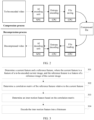
- FIG. 3 is a flowchart of an encoding method according to an embodiment of this application. The method is applied to an encoder side. Refer to FIG. 3 . The method includes the following steps.
- Step 301 Determine a current feature and a reference feature, where the current feature is a feature of a to-be-encoded current image, and the reference feature is a feature of a reference image of the current image.
- the to-be-encoded current image corresponds to the reference image.
- an image of a P frame corresponds to a reference image
- the reference image is an image of an I frame or a P frame before the P frame.
- an image of a B frame corresponds to two reference images, that is, an image of an I frame or a P frame before the B frame and an image of a P frame after the B frame.
- the following uses the P frame as an example for description.
- the image feature extraction network in this embodiment of this application is obtained through pre-training.
- a network structure, a training manner, and the like of the image feature extraction network are not limited in this embodiment of this application.
- the image feature extraction network may be a network constructed based on a fully-connected network or a convolutional neural network, and convolution in the convolutional neural network may be 2D convolution or 3D convolution.
- a quantity of network layers and a quantity of nodes at each layer that are included in the image feature extraction network are not limited in this embodiment of this application.
- the image feature extraction network is a network constructed based on Resblock.
- the reference image is a reconstructed image of a reference frame.
- the reference frame is a reference frame of a to-be-encoded current frame, and an original image of the to-be-encoded current frame is the current image.
- the reconstructed image of the reference frame is an image obtained by performing decompression after an original image of the reference frame is compressed according to the encoding method provided in this embodiment of this application. In some other embodiments, the reference image is the original image of the reference frame.
- Step 302 Determine a correlation matrix of the reference feature relative to the current feature.
- the correlation matrix is introduced in the scheme.
- the encoder side determines the correlation matrix of the reference feature relative to the current feature. For a manner of calculating the correlation matrix, refer to the foregoing description.
- Step 303 Determine the inter motion feature based on the correlation matrix.
- the encoder side inputs the correlation matrix, the current feature, and the reference feature into a motion encoding network to obtain the inter motion feature.
- the encoder side inputs the correlation matrix, the current image, and the reference image into a motion encoding network to obtain the inter motion feature.
- the encoder side inputs the correlation matrix into a motion encoding network to obtain the inter motion feature.
- the encoder side uses the reference feature as a predicted feature, and inputs the correlation matrix, the predicted feature, and the current feature into a motion encoding network to obtain a motion feature.
- the encoder side determines a quantity of iterations. If the quantity of iterations is less than an iteration quantity threshold, the encoder side inputs the motion feature into a motion decoding network to obtain a reconstructed motion feature, transforms the reference feature based on the reconstructed motion feature to re-determine the predicted feature, re-determines a correlation matrix of the predicted feature relative to the current feature, and returns to perform the step of inputting the correlation matrix, the predicted feature, and the current feature into a motion encoding network to obtain a motion feature. If the quantity of iterations is equal to the iteration quantity threshold, the encoder side determines the motion feature as the inter motion feature.
- the quantity of iterations is equal to an initial value
- the quantity of iterations is equal to the iteration quantity threshold.
- the initial value is 0, and the iteration quantity threshold is K-1; or the initial value is 1, and the iteration quantity threshold is K.
- K is a positive integer greater than or equal to 1, and K represents a total quantity of times of iterative processing.
- the total quantity of times of iterative processing is K
- the initial value is 1
- the iteration quantity threshold is K
- the to-be-encoded current image x t is a t th frame in a video
- the reference image of the current image x t is the reconstructed image x ⁇ t -1 of the reference frame
- the current feature is F t
- the reference feature is F ⁇ t -1
- the correlation matrix of the reference feature F ⁇ t -1 relative to the current feature F t is C t .
- the encoder side uses the reference image as a predicted image, and inputs the correlation matrix, the predicted image, and the current image into a motion encoding network to obtain a motion feature.
- the encoder side determines a quantity of iterations.
- the encoder side inputs the motion feature into a motion decoding network to obtain a reconstructed motion feature, transforms the reference image based on the reconstructed motion feature to re-determine a predicted image, determines a predicted feature, that is, a feature of the predicted image, re-determines a correlation matrix of the predicted feature relative to the current feature, and returns to perform the step of inputting the correlation matrix, the predicted image, and the current image into a motion encoding network to obtain a motion feature. If the quantity of iterations is equal to the iteration quantity threshold, the encoder side determines the motion feature as the inter motion feature.
- the encoder side improves the prediction accuracy of the inter motion feature through a plurality of iterations. In other words, motion details are further enriched by iteratively updating the motion feature. However, in the first to the third implementations, the encoder side determines the inter motion feature through one iteration, so that coding time can be reduced.
- FIG. 4 is a comparison diagram of reconstructed motion features according to an embodiment of this application.
- FIG. 4 shows reconstructed motion features of a same image in a video.
- a first column is a reconstructed motion feature obtained after first iterative processing
- a second column is a reconstructed motion feature obtained after second iterative processing.
- some regions with obvious contrast are circled by using ellipses. It can be learned that an edge structure of the second column is clearer, more explicit, and more accurate. In other words, compared with the reconstructed motion feature of the first column, the reconstructed motion feature of the second column has more obvious detail information.
- the motion encoding network and the motion decoding network in this embodiment of this application are obtained through pre-training.
- Network structures, training manners, and the like of the motion encoding network and the motion decoding network are not limited in this embodiment of this application.
- the motion encoding network and the motion decoding network both may be fully-connected networks or convolutional neural networks, and convolution in the convolutional neural network may be 2D convolution or 3D convolution.
- a quantity of network layers and a quantity of nodes at each layer that are included in each of the motion encoding network and the motion decoding network are not limited in this embodiment of this application.
- FIG. 5 is a diagram of a structure of an encoding network according to an embodiment of this application.
- the encoding network may be the motion encoding network. Refer to FIG. 5 .
- the encoding network is a convolutional neural network, and the convolutional neural network includes four convolution layers (Conv) and three grasp detection network (grasp detection network, GDN) layers that are interleaved and concatenated.
- a size of a convolution kernel of each convolution layer is 5 ⁇ 5
- a quantity of channels of an output feature map is M
- downsampling by a factor of 2 is performed on a width and a height at each convolution layer.
- the structure of the encoding network shown in FIG. 5 is not intended to limit this embodiment of this application.
- a size of a convolution kernel, a quantity of channels of a feature map, a downsampling multiple, a quantity of times of downsampling, a quantity of convolution layers, and the like may all be adjusted
- Step 304 Encode the inter motion feature into a bitstream.
- the encoder side encodes the inter motion feature into the bitstream, so that the decoder side subsequently decompresses the video based on the inter motion feature in the bitstream.
- the encoder side encodes the inter motion feature into the bitstream through entropy encoding.
- the encoder side encodes the inter motion feature into the bitstream through entropy encoding based on a specified first probability distribution parameter.
- the encoder side inputs the inter motion feature into a hyper encoder network (which may also be referred to as a hyper-prior network) to obtain a first hyper-prior feature.
- the encoder side encodes the first hyper-prior feature into the bitstream through entropy encoding based on a specified second probability distribution parameter.
- the encoder side inputs the first hyper-prior feature (the first hyper-prior feature obtained by the bitstream or the first hyper-prior feature obtained by using the hyper encoder network) into a hyper decoder network to obtain a first prior feature.
- the encoder side determines probability distribution parameters of the inter motion feature based on the first prior feature, and encodes the inter motion feature into the bitstream through entropy encoding based on the probability distribution parameters of the inter motion feature. It should be noted that the encoder side encodes the first hyper-prior feature into the bitstream, so that the decoder side parses out the inter motion feature from the bitstream based on the first hyper-prior feature.
- Both the specified first probability distribution parameter and the specified second probability distribution parameter are probability distribution parameters that are pre-determined by using a corresponding probability distribution estimation network.
- a network structure and a training method used for the used probability distribution estimation network are not limited in this embodiment of this application.
- the network structure of the probability distribution estimation network may be a fully-connected network or a CNN.
- a quantity of layers and a quantity of nodes at each layer that are included in the network structure of the probability distribution estimation network are not limited in this embodiment of this application.
- the encoder side determines the inter motion feature and encodes the inter motion feature. It should be noted that, for inter prediction coding, in addition to determining and encoding the inter motion feature, the encoder side further determines a residual feature and encodes the residual feature, so that the decoder side decompresses the video based on the inter motion feature and the residual feature.
- the encoding method provided in this embodiment of this application further includes the following step 305 and step 306.
- Step 305 Determine the residual feature based on the inter motion feature.
- the encoder side determines the residual feature based on the inter motion feature.
- the encoder side inputs the inter motion feature into the motion decoding network to obtain the reconstructed motion feature between the current image and the reference image.
- the encoder side transforms the reference feature based on the reconstructed motion feature between the current image and the reference image to obtain the predicted feature of the current image.
- the encoder side determines a first residual, where the first residual is a residual between the predicted feature of the current image and the current feature; and inputs the first residual into a residual encoding network to obtain the residual feature.
- the encoder side performs transformation and prediction in feature space.
- the encoder side inputs the inter motion feature into the motion decoding network to obtain the reconstructed motion feature between the current image and the reference image.
- the encoder side transforms the reference image based on the reconstructed motion feature between the current image and the reference image to obtain a predicted image.
- the encoder side determines a second residual, where the second residual is a residual between the predicted image and the current image; and inputs the second residual into the residual encoding network to obtain the residual feature.
- the predicted image is the predicted image of the current image. In other words, the encoder side performs transformation and prediction in image space.
- the motion decoding network in step 305 and the motion decoding network in step 303 are the same motion decoding network.
- the residual encoding network in step 305 is obtained through pre-training.
- a network structure, a training manner, and the like of the residual encoding network are not limited in this embodiment of this application.
- the residual encoding network may be a fully-connected network or a convolutional neural network, and convolution in the convolutional neural network may be 2D convolution or 3D convolution.
- a quantity of network layers and a quantity of nodes at each layer that are included in the residual encoding network are not limited in this embodiment of this application.
- the network structure of the residual encoding network is also the network structure shown in FIG. 5 .
- the encoder side encodes the residual feature into the bitstream, so that the decoder side subsequently decompresses the video based on the inter motion feature and the residual feature in the bitstream.
- the encoder side encodes the residual feature into the bitstream through entropy encoding.
- the encoder side encodes the residual feature into the bitstream through entropy encoding based on a specified third probability distribution parameter.
- the encoder side inputs the residual feature into the hyper encoder network to obtain a second hyper-prior feature.
- the encoder side encodes the second hyper-prior feature into the bitstream through entropy encoding based on a specified fourth probability distribution parameter.
- the encoder side inputs the second hyper-prior feature (the second hyper-prior feature obtained by parsing the bitstream or the second hyper-prior feature obtained by using the hyper encoder network) into the hyper decoder network to obtain a second prior feature.
- the encoder side determines probability distribution parameters of the residual feature based on the second prior feature, and encodes the residual feature into the bitstream through entropy encoding based on the probability distribution parameters of the residual feature. It should be noted that the encoder side encodes the second hyper-prior feature into the bitstream, so that the decoder side parses out the residual feature from the bitstream based on the second hyper-prior feature.
- Both the specified third probability distribution parameter and the specified fourth probability distribution parameter are probability distribution parameters that are pre-determined by using a corresponding probability distribution estimation network.
- a network structure and a training method used for the used probability distribution estimation network are not limited in this embodiment of this application.
- the network structure of the probability distribution estimation network may be a fully-connected network or a CNN.
- a quantity of layers and a quantity of nodes at each layer that are included in the network structure of the probability distribution estimation network are not limited in this embodiment of this application.
- the hyper encoder network used for encoding the residual feature is the same as or different from the hyper encoder network used for encoding the inter motion feature
- the hyper decoder network used for decoding the residual feature is the same as or different from the hyper decoder network used for decoding the inter motion feature.
- estimated probability distribution parameters include a mean value and a variance.
- the probability distribution parameters that are of the residual feature and that are obtained by using the probability distribution estimation network include a mean value and a variance.
- the estimated probability distribution parameters include a position parameter and a scale parameter.
- the estimated probability distribution parameters include a mean value and a scale parameter.
- the probability distribution estimation network in this embodiment of this application may also be referred to as a factor entropy model, the probability distribution estimation network is a part of the entropy estimation network, and the entropy estimation network further includes the foregoing hyper encoder network and hyper decoder network.
- the hyper encoder network used for encoding the inter motion feature, the probability distribution estimation network, and the hyper decoder network form a part or all of one entropy estimation network
- the hyper encoder network used for encoding the residual feature, the probability distribution estimation network, and the hyper decoder network form a part or all of another entropy estimation network.
- FIG. 8 is a diagram of a structure of an entropy estimation network according to an embodiment of this application.
- the entropy estimation network may be any one of the foregoing entropy estimation networks. Refer to FIG. 8 .
- the entropy estimation network includes a hyper encoder (hyper encoder, HyEnc) network, a factor entropy model, and a hyper decoder (hyper decoder, HyDec) network.
- the hyper encoder network includes three convolution layers (Conv) and two activation layers (such as activation layers constructed based on Relu or another activation function) that are interleaved and concatenated.
- a size of a convolution kernel of each convolution layer is 5 ⁇ 5
- a quantity of channels of an output feature map is M
- downsampling by a factor of 2 is performed on a width and a height at the first two convolution layers
- downsampling is not performed at a last convolution layer.
- a network structure of the factor entropy model is the network structure of the probability distribution estimation network described above.
- the hyper encoder network includes three convolution layers (Conv) and two activation layers (such as activation layers constructed based on Relu or another activation function) that are interleaved and concatenated.
- the encoder side first obtains the residual (the first residual or the second residual), then obtains the residual feature, and further encodes the residual feature. This is equivalent to compressing the residual.
- the encoder side may directly encode the residual into the bitstream after obtaining the residual. In other words, the residual is not compressed.
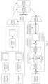
- FIG. 9 is a flowchart of a video coding/decoding method according to an embodiment of this application.
- a to-be-encoded current image x t is a t th frame in a video, t>0
- a reference image of the current image x t is a reconstructed image x ⁇ t -1 of a reference frame.
- An encoding process of encoding the current image x t includes the following step 901 to step 910.
- Step 901 Separately input the current image x t and the reference image x ⁇ t -1 into an image feature extraction network to obtain a current feature F t and a reference feature F ⁇ t- 1 .
- Dimensions of the current feature F t and reference feature F ⁇ t -1 are both c1*h1*w1.
- Step 902 Calculate a correlation matrix C t of the reference feature F ⁇ t -1 relative to the current feature F t .
- a dimension of the correlation matrix C t is k*k*h1*w1.
- Step 903 Input the correlation matrix C t , the current feature F t , and the reference feature F ⁇ t -1 into a motion encoding network to obtain an inter motion feature m ⁇ t .
- the inter motion feature m ⁇ t is a to-be-encoded motion feature.
- a dimension of the inter motion feature m ⁇ t is c1*h2*w2, and generally, h2 ⁇ h1, and w2 ⁇ w1.
- Step 905 Encode the inter motion feature m ⁇ t into a bitstream through entropy encoding based on the probability distribution parameters corresponding to each element in the inter motion feature m ⁇ t .
- the bitstream is a bit stream
- a bit sequence obtained by performing entropy encoding on the inter motion feature m ⁇ t is a part of a bit sequence included in the bitstream, and this part of the bit sequence is referred to as a motion information bitstream or a motion information bit stream.
- Step 908 Calculate a residual between the current feature F t and the predicted feature F ⁇ t , and input the residual into a residual encoding network to obtain a residual feature r ⁇ t .
- the residual feature r ⁇ t is a to-be-encoded residual feature.
- Step 909 Determine, by using the entropy estimation network, probability distribution parameters corresponding to each element in the residual feature r ⁇ t , for example, a mean value ⁇ r,t and a variance ⁇ m , t .
- Step 910 Encode the residual feature r ⁇ t into the bitstream through entropy encoding based on the probability distribution parameters corresponding to each element in the residual feature r ⁇ t . It is assumed that the bitstream is a bit stream, a bit sequence obtained by performing entropy encoding on the residual feature r ⁇ t is a part of a bit sequence included in the bitstream, and this part of the bit sequence is referred to as a residual information bitstream or a motion information bit stream.
- the image reconstruction network is not shown in FIG. 9
- the image reconstruction network may be a deconvolutional network, and the image reconstruction network may match the image feature extraction network.
- the residual decoding network is obtained through pre-training.
- a network structure, a training manner, and the like of the residual decoding network are not limited in this embodiment of this application.
- the residual decoding network may be a fully-connected network or a convolutional neural network.
- a quantity of network layers and a quantity of nodes at each layer that are included in the residual decoding network are not limited in this embodiment of this application.
- the network structure of the residual decoding network may be the network structure shown in FIG. 6 .
- the foregoing step 903 may be replaced with: inputting the correlation matrix C t , the current image x t , and the reference image x ⁇ t -1 into the motion encoding network to obtain the inter motion feature m ⁇ t , to obtain another embodiment.
- step 907 may also be replaced with: transforming the reference image x ⁇ t -1 into a predicted image x ⁇ t by using the reconstructed motion feature M t
- step 908 is replaced with: calculating a residual between the current image x t and the predicted image x ⁇ t , and inputting the residual into the residual encoding network to obtain the residual feature r ⁇ t , to obtain still another embodiment.
- a difference between a subsequent step of obtaining the reconstructed image x ⁇ t of the current frame and the step described in the previous paragraph lies in: obtaining the reconstructed image x t of the current frame based on the predicted image x ⁇ t and the reconstructed residual.
- the inter motion feature is not obtained through a plurality of iterations. If a reconstructed motion feature with richer details is needed, an iterative procedure (for example, an iterative procedure shown in FIG. 10 below) described in the foregoing step 303 may be applied to the video coding/decoding method shown in FIG. 9 , to obtain an inter motion feature with higher accuracy through a plurality of iterations.
- an iterative procedure for example, an iterative procedure shown in FIG. 10 below
- FIG. 10 is a partial flowchart of an encoding method according to an embodiment of this application.
- a total quantity of times of iterative processing is K
- an initial value is 0
- a threshold of a quantity of iterations is K-1
- a to-be-encoded current image x t is a t th frame in a video, t>0
- a reference image of the current image x t is a reconstructed image x ⁇ t -1 of a reference frame.
- An encoding process of encoding the current image x t includes the following step 1001 to step 1010.
- Step 1001 Separately input the current image x t and the reference image x ⁇ t -1 into an image feature extraction network to obtain a current feature F t and a reference feature F ⁇ t -1 .
- Step 1003 Use the reference feature F t- 1 as a predicted feature F ⁇ t of first iterative processing, and use the correlation matrix C t as a correlation matrix of the predicted feature F ⁇ t relative to the current feature F t .
- Step 1004 Input the correlation matrix C t , the predicted feature F ⁇ t , and the current feature F t into a motion encoding network to obtain a motion feature m ⁇ t , and determine a quantity i of iterations.
- a quantity i of iterations determined for the first time is 0, and after the first time, a quantity of iterations determined each time is equal to a quantity of iterations determined last time plus 1.
- Step 1007 Transform the reference feature F ⁇ t -1 based on the reconstructed motion feature M t to re-predict the feature F ⁇ t .
- Step 1008 Re-determine the correlation matrix C t of the predicted feature F ⁇ t relative to the current feature F t , and return to step 1004.
- Step 1009 Determine, by using an entropy estimation network, probability distribution parameters corresponding to each element in the inter motion feature m ⁇ t .
- Step 1010 Encode the inter motion feature m ⁇ t into a bitstream through entropy encoding based on the probability distribution parameters corresponding to each element in the inter motion feature m ⁇ t .
- Step 1011 Input the inter motion feature m ⁇ t into a motion decoding network to obtain the reconstructed motion feature M t .
- Step 1012 Transform the reference feature F ⁇ t -1 into the predicted feature F ⁇ t by using the reconstructed motion feature M t .
- Step 1013 Calculate a residual between the current feature F t and the predicted feature F ⁇ t , and input the residual into a residual encoding network to obtain a residual feature r ⁇ t .
- Step 1014 Determine, by using the entropy estimation network, probability distribution parameters corresponding to each element in the residual feature r ⁇ t .
- Step 1015 Encode the residual feature r ⁇ t into the bitstream through entropy encoding based on the probability distribution parameters corresponding to each element in the residual feature r ⁇ t .
- FIG. 11 is another comparison diagram of reconstructed motion features according to an embodiment of this application.
- FIG. 11 shows reconstructed motion features of a same image in a video.
- a first row is a reconstructed motion feature obtained in the video coding/decoding method shown in FIG. 9
- a second row is a reconstructed motion feature obtained in a related technology.
- image features of a current frame and a reference frame are input into a convolutional neural network, so that motion between the current frame and the reference frame is fitted completely based on a convolution operation. It can be learned that an edge structure of the first row is clearer, more explicit, and more accurate. In other words, compared with the reconstructed motion feature of the second row, the reconstructed motion feature of the first row has more obvious detail information.
- this scheme can be applied to both a P frame and a B frame, and the foregoing encoding process uses the P frame as an example.
- a current image corresponds to two reference images.
- the encoder side obtains two inter motion features and two residual features based on the two reference images according to the foregoing method, and encodes the two inter motion features and the two residual features into a bitstream.
- the two inter motion features respectively correspond to the two reference images, and the two residual features also respectively correspond to the two reference images.
- the encoder side obtains two inter motion features based on the two reference images according to the foregoing method, and encodes the two inter motion features into a bitstream.
- the encoder side transforms a reference feature based on the two inter motion features to separately obtain two predicted features, fuses the two predicted features to obtain a fused predicted feature, obtains a residual feature based on the fused predicted feature and a current feature, and encodes the residual feature into the bitstream.
- the test set includes a class B video, a class C video, and a class D video in a joint video experts team (joint video experts team, JVET) standard test set, and some videos in a YUV_CTC video set.
- a resolution of the class B video is 1920* 1080
- a resolution of the class C video is 832*480
- a resolution of the class D video is 416*240.
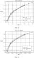
- FIG. 12 to FIG. 15 are comparison diagrams of coding performance according to an embodiment of this application.
- FIG. 12 to FIG. 14 are respectively test results for the class B video, the class C video, and the class D video, and FIG.
- FIG. 15 is a test result for a video in the YUV_CTC video set.
- "Corr” represents this scheme, that is, an inter prediction coding scheme based on a correlation matrix.
- Optical flow in the legends represents a comparison scheme 1, that is, an inter prediction coding scheme based on optical flow estimation.
- “FVC” in the legends represents a comparison scheme 2, that is, an encoding scheme for obtaining an inter motion feature only based on features of a current frame and a reference frame.
- a higher performance indicator PSNR indicates better quality of a reconstructed image
- a larger BPP indicates a lower compression rate and lower quality of a reconstructed image. It can be learned that a curve corresponding to this scheme is closer to the top and is closer to the left. This indicates that the coding performance of this scheme is better, that is, compression performance is better.
- this scheme does not depend on an optical flow, so that a calculation amount of calculating the optical flow is reduced, it is easier to predict the inter motion feature, and it is easier to predict an inter motion feature that is more conducive to compression.
- a correlation matrix is introduced. This helps improve prediction accuracy of the inter motion feature, makes inter prediction and compression simpler, and helps improve a fitting and generalization capability of an entire coding model.
- the correlation matrix is introduced to fit inter motion. Because the correlation matrix can represent a part with strong correlation and a part with weak correlation between a current feature and a reference feature, and inter motion information corresponding to the part with strong correlation is richer, in a process of fitting the inter motion, inter motion corresponding to the part with strong correlation can be better fitted based on a size of each element in the correlation matrix, and less attention is paid to inter motion corresponding to the part with weak correlation.
- the correlation matrix has an information enhancement function for prediction of the inter motion feature, that is, can improve prediction accuracy of the inter motion feature and further improve compression performance.
- FIG. 16 is a flowchart of a decoding method according to an embodiment of this application. The method is applied to a decoder side. Refer to FIG. 16 . The method includes the following steps.
- Step 1601 Parse out an inter motion feature and a residual feature from a bitstream.
- the inter motion feature encoded into the bitstream is determined based on a correlation matrix of a reference feature relative to a current feature.
- the decoder side parses out the inter motion feature from the bitstream through entropy decoding.
- the decoder side parses out the inter motion feature from the bitstream through entropy decoding based on a specified first probability distribution parameter.
- the decoder side parses out a first hyper-prior feature from the bitstream based on a specified second probability distribution parameter, and inputs the first hyper-prior feature into a hyper decoder network to obtain a first prior feature.
- the decoder side determines probability distribution parameters of the inter motion feature based on the first prior feature, and parses out the inter motion feature from the bitstream based on the probability distribution parameters of the inter motion feature.
- first probability distribution parameter, the second probability distribution parameter, the third probability distribution parameter, and the fourth probability distribution parameter in a decoding process are the same as those in the encoding process, and the hyper decoder network used in the decoding process is the same as the hyper decoder network used in the encoding process.
- Step 1602 Determine a predicted feature of a to-be-decoded current image based on the inter motion feature and the reference feature.
- the decoder side inputs the inter motion feature into a motion decoding network to obtain a reconstructed motion feature between the current image and a reference image.
- the decoder side transforms the reference feature based on the reconstructed motion feature to obtain the predicted feature of the current image.
- Step 1603 Reconstruct the current image based on the predicted feature and the residual feature.
- the decoder side obtains a reconstructed feature of the current image based on the residual feature and the predicted feature.
- the decoder side inputs the reconstructed feature of the current image into an image reconstruction network to reconstruct the current image, that is, obtain a reconstructed image of a current frame.
- the decoder side may input the residual feature into a residual decoding network to obtain a reconstructed residual, and obtain the reconstructed feature of the current image based on the predicted feature and the reconstructed residual.
- step 1602 and step 1603 are replaced with: determining a predicted image of a to-be-decoded current image based on the inter motion feature and a reference image, and reconstructing a current feature based on the predicted image and the residual feature.
- the decoder side may input the inter motion feature into the motion decoding network to obtain the reconstructed motion feature.
- the decoder side transforms the reference image based on the reconstructed motion feature to obtain the predicted image of the current image.
- the decoder side may input the residual feature into the residual decoding network to obtain the reconstructed residual, and reconstruct the current image based on the predicted image and the reconstructed residual.
- the decoder side parses out the inter motion feature and a residual from the bitstream, and inputs the inter motion feature into the motion decoding network to obtain the reconstructed motion feature between the current image and the reference image.
- the decoder side transforms the reference feature based on the reconstructed motion feature to obtain the predicted feature of the current image.
- the decoder side obtains the reconstructed feature of the current image based on the predicted feature and the parsed-out residual, and inputs the reconstructed feature of the current image into the image reconstruction network to reconstruct the current image.
- the decoder side parses out the inter motion feature and a residual from the bitstream, and inputs the inter motion feature into the motion decoding network to obtain the reconstructed motion feature between the current image and the reference image.
- the decoder side transforms the reference image based on the reconstructed motion feature to obtain the predicted image of the current image.
- the decoder side reconstructs the current image based on the predicted image and the parsed-out residual.
- the decoding process in any one of the foregoing embodiments matches the encoding process. For example, if the encoding process is to perform transformation and prediction in image space, the decoding process is also to perform transformation and prediction in the image space. If the encoding process is to perform transformation and prediction in feature space, the decoding process is also to perform transformation and prediction in the feature space.
- the correlation matrix is introduced to fit inter motion.
- the correlation matrix has an information enhancement function for prediction of the inter motion feature, that is, can improve prediction accuracy of the inter motion feature and further improve compression performance.
- FIG. 17 is a diagram of a structure of an encoding apparatus 1700 according to an embodiment of this application.
- the encoding apparatus 1700 may be implemented as a part or an entirety of a computer device by using software, hardware, or a combination of software and hardware.
- the computer device may include any encoder side in the foregoing embodiments. Refer to FIG. 17 .
- the apparatus 1700 includes: a first determining module 1701, a second determining module 1702, a third determining module 1703, and a first encoding module 1704.
- the first determining module 1701 is configured to determine a current feature and a reference feature, where the current feature is a feature of a to-be-encoded current image, and the reference feature is a feature of a reference image of the current image.
- the second determining module 1702 is configured to determine a correlation matrix of the reference feature relative to the current feature.
- the third determining module 1703 is configured to determine an inter motion feature based on the correlation matrix.
- the first encoding module 1704 is configured to encode the inter motion feature into a bitstream.
- the third determining module 1703 is configured to:
- the third determining module 1703 is configured to:
- the apparatus 1700 further includes:
- the fourth determining module is configured to:
- the fourth determining module is configured to:
- the reference image is a reconstructed image of a reference frame.
- the correlation matrix is introduced to fit inter motion. Because the correlation matrix can represent a part with strong correlation and a part with weak correlation between the current feature and the reference feature, and inter motion information corresponding to the part with strong correlation is richer, in a process of fitting the inter motion, inter motion corresponding to the part with strong correlation can be better fitted based on a size of each element in the correlation matrix, and less attention is paid to inter motion corresponding to the part with weak correlation.
- the correlation matrix has an information enhancement function for prediction of the inter motion feature, that is, can improve prediction accuracy of the inter motion feature and further improve compression performance.
- the encoding apparatus provided in the foregoing embodiment performs video coding
- division into the foregoing functional modules is merely used as an example for description.
- the foregoing functions may be allocated to different functional modules for implementation according to a requirement.
- an internal structure of the apparatus is divided into different functional modules to implement all or some of the functions described above.
- the encoding apparatus provided in the foregoing embodiment and the encoding method embodiment belong to a same concept. For a specific implementation process of the encoding apparatus, refer to the method embodiment for details. Details are not described herein again.
- FIG. 18 is a block diagram of a coding apparatus 1800 according to an embodiment of this application.
- the coding apparatus 1800 may include a processor 1801, a memory 1802, and a bus system 1803.
- the processor 1801 and the memory 1802 are connected through the bus system 1803.
- the memory 1802 is configured to store instructions.
- the processor 1801 is configured to execute the instructions stored in the memory 1802, to perform the encoding or decoding method described in embodiments of this application. To avoid repetition, details are not described herein again.
- the processor 1801 may be a central processing unit (CPU), or the processor 1801 may be another general-purpose processor, a DSP, an ASIC, an FPGA or another programmable logic device, a discrete gate or a transistor logic device, a discrete hardware component, or the like.
- the general-purpose processor may be a microprocessor, or the processor may be any conventional processor or the like.
- the memory 1802 may include a ROM device or a RAM device. Any another suitable type of storage device may also be used as the memory 1802.
- the memory 1802 may include code and data 18021 accessed by the processor 1801 through a bus 1803.
- the memory 1802 may further include an operating system 18023 and an application 18022.
- the application 18022 includes at least one program that allows the processor 1801 to perform the encoding or decoding method described in embodiments of this application.
- the application 18022 may include applications 1 to N, and further include an encoding or decoding application (referred to as a coding application for short) for performing the encoding or decoding method described in embodiments of this application.
- the bus system 1803 may further include a power bus, a control bus, a status signal bus, and the like. However, for clear description, various types of buses in the figure are marked as the bus system 1803.
- the coding apparatus 1800 may further include one or more output devices, such as a display 1804.
- the display 1804 may be a touch-sensitive display that combines a display with a touch-sensitive unit that is operable to sense a touch input.
- the display 1804 may be connected to the processor 1801 through the bus 1803.
- the coding apparatus 1800 may perform the encoding method in embodiments of this application or the decoding method in embodiments of this application.
- the computer-readable medium may include a computer-readable storage medium corresponding to a tangible medium such as a data storage medium, or may include any communication medium that facilitates transmission of a computer program from one place to another place (for example, according to a communication protocol).
- the computer-readable medium may generally correspond to: (1) a non-transitory tangible computer-readable storage medium, or (2) a communication medium such as a signal or a carrier.
- the data storage medium may be any usable medium that can be accessed by one or more computers or one or more processors to retrieve instructions, code, and/or data structures for implementing the technologies described in this application.
- a computer program product may include a computer-readable medium.
- the coaxial cable, the optical fiber, the twisted pair, the DSL, or the wireless technology such as infrared, radio, or microwave is included in a definition of the medium.
- the computer-readable storage medium and the data storage medium do not include connections, carriers, signals, or other transitory media, but are actually non-transitory tangible storage media.
- Disks and discs used in this specification include a compact disc (CD), a laser disc, an optical disc, a DVD, and a Blu-ray disc.
- the disks usually reproduce data magnetically, and the discs reproduce data optically by using lasers. Combinations of the foregoing items should also be included in the scope of the computer-readable medium.
- Technologies in embodiments of this application may be implemented in various apparatuses or devices, including a wireless handset, an integrated circuit (IC), or a set of ICs (for example, a chip set).
- IC integrated circuit
- Various components, modules, or units are described in embodiments of this application to emphasize functional aspects of apparatuses configured to perform disclosed technologies, but do not necessarily need to be implemented by different hardware units.
- various units may be combined into a codec hardware unit in combination with appropriate software and/or firmware, or may be provided by an interoperable hardware unit (including one or more processors described above).
- All or some of the foregoing embodiments may be implemented by software, hardware, firmware, or any combination thereof.
- software is used to implement embodiments, all or some of embodiments may be implemented in a form of a computer program product.
- the computer program product includes one or more computer instructions. When the computer instructions are loaded and executed on a computer, a procedure or functions according to embodiments of this application are all or partially generated.
- the computer may be a general-purpose computer, a dedicated computer, a computer network, or another programmable apparatus.
- the computer instructions may be stored in a computer-readable storage medium, or may be transmitted from one computer-readable storage medium to another computer-readable storage medium.
- the computer instructions may be transmitted from a website, computer, server, or data center to another website, computer, server, or data center in a wired (for example, a coaxial cable, an optical fiber, or a digital subscriber line (digital subscriber line, DSL)) or wireless (for example, infrared, radio, or microwave) manner.
- the computer-readable storage medium may be any usable medium accessible by a computer, or a data storage device, such as a server or a data center, integrating one or more usable media.
- information including but not limited to user equipment information, personal information of a user, and the like
- data including but not limited to data used for analysis, stored data, displayed data, and the like
- signals in embodiments of this application are used under authorization by the user or full authorization by all parties, and capturing, using, and processing of related data need to conform to related laws, regulations, and standards of related countries and regions.
- videos, images, and the like related in embodiments of this application are obtained under full authorization.
Landscapes
- Engineering & Computer Science (AREA)
- Multimedia (AREA)
- Signal Processing (AREA)
- Physics & Mathematics (AREA)
- Theoretical Computer Science (AREA)
- Data Mining & Analysis (AREA)
- General Health & Medical Sciences (AREA)
- Biomedical Technology (AREA)
- Biophysics (AREA)
- Computational Linguistics (AREA)
- Life Sciences & Earth Sciences (AREA)
- Evolutionary Computation (AREA)
- Artificial Intelligence (AREA)
- Molecular Biology (AREA)
- Computing Systems (AREA)
- General Engineering & Computer Science (AREA)
- General Physics & Mathematics (AREA)
- Mathematical Physics (AREA)
- Software Systems (AREA)
- Health & Medical Sciences (AREA)
- Compression Or Coding Systems Of Tv Signals (AREA)
Applications Claiming Priority (2)
| Application Number | Priority Date | Filing Date | Title |
|---|---|---|---|
| CN202210345172.7A CN116962715A (zh) | 2022-03-31 | 2022-03-31 | 编码方法、装置、存储介质及计算机程序产品 |
| PCT/CN2023/076925 WO2023185305A1 (fr) | 2022-03-31 | 2023-02-17 | Procédé et appareil de codage, support de stockage et produit-programme d'ordinateur |
Publications (2)
| Publication Number | Publication Date |
|---|---|
| EP4485932A1 true EP4485932A1 (fr) | 2025-01-01 |
| EP4485932A4 EP4485932A4 (fr) | 2025-05-07 |
Family
ID=88199134
Family Applications (1)
| Application Number | Title | Priority Date | Filing Date |
|---|---|---|---|
| EP23777684.4A Pending EP4485932A4 (fr) | 2022-03-31 | 2023-02-17 | Procédé et appareil de codage, support de stockage et produit-programme d'ordinateur |
Country Status (4)
| Country | Link |
|---|---|
| US (1) | US20250024064A1 (fr) |
| EP (1) | EP4485932A4 (fr) |
| CN (1) | CN116962715A (fr) |
| WO (1) | WO2023185305A1 (fr) |
Families Citing this family (3)
| Publication number | Priority date | Publication date | Assignee | Title |
|---|---|---|---|---|
| CN117896525A (zh) * | 2024-01-16 | 2024-04-16 | 镕铭微电子(济南)有限公司 | 视频处理、模型训练方法、装置、电子设备及存储介质 |
| CN120378612A (zh) * | 2024-01-23 | 2025-07-25 | 华为技术有限公司 | 编解码方法以及相关装置 |
| CN121284252B (zh) * | 2025-12-10 | 2026-02-24 | 瀚博半导体(上海)股份有限公司 | 一种解码图像的方法、装置和介质 |
Family Cites Families (13)
| Publication number | Priority date | Publication date | Assignee | Title |
|---|---|---|---|---|
| EP1841230A1 (fr) * | 2006-03-27 | 2007-10-03 | Matsushita Electric Industrial Co., Ltd. | Filtre de Wiener adaptif pour codage vidéo |
| CN100415002C (zh) * | 2006-08-11 | 2008-08-27 | 宁波大学 | 多模式多视点视频信号编码压缩方法 |
| KR101375667B1 (ko) * | 2008-05-16 | 2014-03-18 | 삼성전자주식회사 | 영상의 부호화, 복호화 방법 및 장치 |
| CN106878668B (zh) * | 2015-12-10 | 2020-07-17 | 微软技术许可有限责任公司 | 对物体的移动检测 |
| CN117041547A (zh) * | 2016-04-29 | 2023-11-10 | 世宗大学校产学协力团 | 用于对图像信号进行编码/解码的方法和设备 |
| WO2019009448A1 (fr) * | 2017-07-06 | 2019-01-10 | 삼성전자 주식회사 | Procédé et dispositif de codage ou de décodage d'image |
| US11451807B2 (en) * | 2018-08-08 | 2022-09-20 | Tencent America LLC | Method and apparatus for video coding |
| US10986325B2 (en) * | 2018-09-12 | 2021-04-20 | Nvidia Corporation | Scene flow estimation using shared features |
| US11284066B2 (en) * | 2018-10-10 | 2022-03-22 | Tencent America LLC | Method and apparatus for intra block copy in intra-inter blending mode and triangle prediction unit mode |
| WO2021211966A1 (fr) * | 2020-04-18 | 2021-10-21 | Alibaba Group Holding Limited | Filtre basé sur un réseau neuronal convolutif pour codage vidéo |
| CN116368799A (zh) * | 2020-10-15 | 2023-06-30 | 北京达佳互联信息技术有限公司 | 用于帧间编解码的增强型运动估计 |
| CN112767277B (zh) * | 2021-01-27 | 2022-06-07 | 同济大学 | 一种基于参考图像的深度特征排序去模糊方法 |
| CN113570606B (zh) * | 2021-06-30 | 2023-09-05 | 北京百度网讯科技有限公司 | 目标分割的方法、装置及电子设备 |
-
2022
- 2022-03-31 CN CN202210345172.7A patent/CN116962715A/zh active Pending
-
2023
- 2023-02-17 WO PCT/CN2023/076925 patent/WO2023185305A1/fr not_active Ceased
- 2023-02-17 EP EP23777684.4A patent/EP4485932A4/fr active Pending
-
2024
- 2024-09-27 US US18/899,403 patent/US20250024064A1/en active Pending
Also Published As
| Publication number | Publication date |
|---|---|
| US20250024064A1 (en) | 2025-01-16 |
| CN116962715A (zh) | 2023-10-27 |
| EP4485932A4 (fr) | 2025-05-07 |
| WO2023185305A1 (fr) | 2023-10-05 |
Similar Documents
| Publication | Publication Date | Title |
|---|---|---|
| US20250024064A1 (en) | Encoding Method and Apparatus, Storage Medium, and Computer Program Product | |
| CN115118972B (zh) | 视频图像的编解码方法及相关设备 | |
| CN111327902B (zh) | 点云的编解码方法及装置 | |
| CN110248189B (zh) | 一种视频质量预测方法、装置、介质和电子设备 | |
| US12531995B2 (en) | Encoding method and apparatus, decoding method and apparatus, device, storage medium, and computer program product | |
| CN113747242A (zh) | 图像处理方法、装置、电子设备及存储介质 | |
| US20240242467A1 (en) | Video encoding and decoding method, encoder, decoder and storage medium | |
| CN110677676B (zh) | 视频编码方法和装置、视频解码方法和装置及存储介质 | |
| CN115063494B (zh) | 火星图像压缩方法、装置、计算机设备和存储介质 | |
| CN116132684A (zh) | 视频编解码方法、装置、设备、存储介质及计算机程序 | |
| CN110996108A (zh) | 一种视频帧重构方法、装置及终端设备 | |
| US12412587B2 (en) | Encoding method and apparatus, decoding method and apparatus, device, storage medium, and computer program | |
| JP7858084B2 (ja) | フィルタリング方法、フィルタリングモデル訓練方法及び関連する装置 | |
| CN110572676B (zh) | 视频编码方法和装置、视频解码方法和装置及存储介质 | |
| CN118474384A (zh) | 编解码方法、装置、设备、存储介质及计算机程序 | |
| CN121126003A (zh) | 编解码方法、装置、设备、存储介质及程序产品 | |
| CN120201201A (zh) | 编解码方法、图像分类方法以及相关装置 | |
| CN121967698A (zh) | 一种视频编解码方法、装置、设备、介质及程序产品 | |
| WO2025087214A1 (fr) | Décodeur, codeur, procédé de codage d'image, procédé de décodage d'image et support de stockage | |
| WO2025156771A1 (fr) | Procédé de codage, procédé de décodage et appareils associés | |
| CN121000875A (zh) | 一种三维高斯处理方法、装置、设备、介质及程序产品 | |
| CN120915966A (zh) | 编解码方法、装置和电子设备 | |
| CN118612451A (zh) | 编解码方法、装置、设备、存储介质及计算机程序 | |
| CN115412727A (zh) | 编码方法、解码方法及其装置 | |
| HK40019527B (zh) | 视频编码方法和装置、视频解码方法和装置及存储介质 |
Legal Events
| Date | Code | Title | Description |
|---|---|---|---|
| STAA | Information on the status of an ep patent application or granted ep patent |
Free format text: STATUS: THE INTERNATIONAL PUBLICATION HAS BEEN MADE |
|
| PUAI | Public reference made under article 153(3) epc to a published international application that has entered the european phase |
Free format text: ORIGINAL CODE: 0009012 |
|
| STAA | Information on the status of an ep patent application or granted ep patent |
Free format text: STATUS: REQUEST FOR EXAMINATION WAS MADE |
|
| 17P | Request for examination filed |
Effective date: 20240924 |
|
| AK | Designated contracting states |
Kind code of ref document: A1 Designated state(s): AL AT BE BG CH CY CZ DE DK EE ES FI FR GB GR HR HU IE IS IT LI LT LU LV MC ME MK MT NL NO PL PT RO RS SE SI SK SM TR |
|
| REG | Reference to a national code |
Ref country code: DE Ref legal event code: R079 Free format text: PREVIOUS MAIN CLASS: H04N0019503000 Ipc: H04N0019527000 |
|
| A4 | Supplementary search report drawn up and despatched |
Effective date: 20250407 |
|
| RIC1 | Information provided on ipc code assigned before grant |
Ipc: H04N 19/136 20140101ALI20250401BHEP Ipc: H04N 19/172 20140101ALI20250401BHEP Ipc: H04N 19/527 20140101AFI20250401BHEP |
|
| DAV | Request for validation of the european patent (deleted) | ||
| DAX | Request for extension of the european patent (deleted) |