EP4486471B1 - Snowboard-bindung mit einer stützschale, die mehrere schliesspositionen aufweist, die durch eine mehrkerbige verriegelung bestimmt werden - Google Patents
Snowboard-bindung mit einer stützschale, die mehrere schliesspositionen aufweist, die durch eine mehrkerbige verriegelung bestimmt werden Download PDFInfo
- Publication number
- EP4486471B1 EP4486471B1 EP21701956.1A EP21701956A EP4486471B1 EP 4486471 B1 EP4486471 B1 EP 4486471B1 EP 21701956 A EP21701956 A EP 21701956A EP 4486471 B1 EP4486471 B1 EP 4486471B1
- Authority
- EP
- European Patent Office
- Prior art keywords
- highback
- lug
- lever
- snowboard binding
- arm
- Prior art date
- Legal status (The legal status is an assumption and is not a legal conclusion. Google has not performed a legal analysis and makes no representation as to the accuracy of the status listed.)
- Active
Links
Images

Classifications
-
- A—HUMAN NECESSITIES
- A63—SPORTS; GAMES; AMUSEMENTS
- A63C—SKATES; SKIS; ROLLER SKATES; DESIGN OR LAYOUT OF COURTS, RINKS OR THE LIKE
- A63C10/00—Snowboard bindings
- A63C10/02—Snowboard bindings characterised by details of the shoe holders
- A63C10/04—Shoe holders for passing over the shoe
- A63C10/045—Shoe holders for passing over the shoe with means to ease introduction of the shoe, e.g. by collapsing upstanding shoe holder parts
-
- A—HUMAN NECESSITIES
- A63—SPORTS; GAMES; AMUSEMENTS
- A63C—SKATES; SKIS; ROLLER SKATES; DESIGN OR LAYOUT OF COURTS, RINKS OR THE LIKE
- A63C10/00—Snowboard bindings
- A63C10/24—Calf or heel supports, e.g. adjustable high back or heel loops
-
- A—HUMAN NECESSITIES
- A63—SPORTS; GAMES; AMUSEMENTS
- A63C—SKATES; SKIS; ROLLER SKATES; DESIGN OR LAYOUT OF COURTS, RINKS OR THE LIKE
- A63C2203/00—Special features of skates, skis, roller-skates, snowboards and courts
- A63C2203/10—Special features of skates, skis, roller-skates, snowboards and courts enabling folding, collapsing
Definitions
- the invention relates to a snowboard binding comprising more particularly a base, a support shell movable relative to the base and a pedal for controlling the support shell when putting on the boot, in rotation relative to the base between an open position and a closed position.
- a means is provided for blocking the rotation of the support shell relative to the base in the closed position, against the elastic return of a lever.
- the means comprises two notches for snapping with the lever.
- a snowboard binding of this type is known from document patcit0001: US 2016175689 A --.
- the elastic return lever is manually tilted to unlock the support shell from the closed position and allow the shoe to be removed.
- One of the aims of the invention is thus to modify the type of snowboard binding described above, to guarantee the blocking of the support shell in the closed position, in all circumstances.
- the invention relates to a snowboard binding in accordance with the introductory description, characterized in that it comprises a lug received in a fork of the notched means or the lever to rotate the locking means or the lever, by unclicking the lever from one of the notches and by snapping it into the other notch during putting on.
- the snowboard binding according to the invention allows the lever, by driving the fork by means of the lug, to snap into different closing positions during putting on, determined by the different notches of the locking means.
- the lug can be fixed in the base, the support shell or the pedal.
- the notched means comprises a wheel provided with a notch forming the fork receiving the lug.
- the wheel can be movable in rotation relative to the support shell and the lug, fixed in the base.
- the wheel can be movable relative to the base and the lug, fixed in the support shell or in the pedal.
- the lever comprises a first arm movable in rotation relative to the support shell and a second arm, articulated to the first arm and snapped with the notched means, which is fixed in the support shell, the first arm of the lever provided with a notch forming the fork, opposite the second arm and the lug being fixed in the base.
- the lug is carried by a hull side of the support hull.
- the first arm of the lever is an arch articulated to two hull sides of the support hull.
- a hull bottom of the support shell or the base comprises a hinge bearing, mounted around the axis of rotation of the support shell relative to the base, serving as a guide stop in any position of the support shell, between the open position and the closing positions, when putting on and taking off shoes.
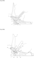
- a snowboard binding illustrated by one of the figures 1 to 7 , comprises a base 1, a support shell 3, a pedal 5 and a strap 7.
- the support shell 3 is movable around the axis of rotation A1 carried by the base 1.
- the pedal 5 and the strap 7 are provided to control the support shell 3 respectively when putting on and taking off the shoe, between an open position and a closed position.
- the support shell 3 comprises a shell bottom 9 and two shell sides 11.
- the pedal 5 is articulated to the two shell sides 11 around an axis of rotation A2.
- the strap 7 is articulated to the support shell 3 around an axis of rotation A3.
- a means 15, 16 is provided to block the rotation of the support shell 3 relative to the base 1 in the closed position, against an elastic return lever 13, 13a, 13b. This means 15, 16 comprises two or more snap-in notches 17.
- the elastic return lever includes an operating arm 12 to be manually released in order to unlock the support shell from the closed position and allow the shoe to be removed.
- the snowboard binding comprises a lug 21 received in a fork 20 of the means 15, 16 with notches 17 or of the lever 13, 13a, 13b to drive the means with notches or the rotating lever, by unclicking the lever from one of the notches 17 and clicking with the other notch 17 during putting on.
- THE figures 1 to 4 illustrate a first embodiment, in which the means 15 with notches 17 comprises a cam or a wheel provided with a notch 23 forming the fork 20 receiving the lug 21.
- the wheel 15 is carried by the base 1 around an axis of rotation A5 to be controlled by the lug 21, carried, Figure 1 , by two lateral arms 19 themselves carrying the pedal 5 or carried, Figure 2 Or 3 , by the hull sides 11, in this case following the axis A3 of articulation of the strap 7.
- the elastic return lever 13 is movable relative to the base 1 around an axis of rotation A4 and provided with a notch 25 for snapping into the notches 17 of the wheel 15.
- the elastic return of the lever 13, obtained by a means known per se and not shown in the figures, for example a spring, allows it to be in abutment against the wheel 15 while the latter is driven in rotation by the lug 21.
- the driving of the wheel 15 by the lug 21 allows, while the support shell 3 is driven in rotation around the axis A1 by the pedal 5 during fitting, the lever 13 to be released from a notch 17 to engage with the following notch, so that the wheel 15 orders the succession of the different closing positions according to the succession of the notches.
- the wheel 15 is rotatable relative to the hull sides 11 and the lug 21 is fixed to the base 1.
- the lever 13 with elastic return is also rotatable relative to the hull sides 11.
- the lateral arms 19 of the pedal 5 are only articulated to the support shell 3, whereas they are also articulated to the base 1 in the example of 1a Figure 3 .
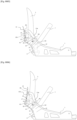
- FIGS. 5 and 6 illustrate a second embodiment, in which the lever 13 comprises a first arm 13a movable relative to the support shell 3 around an axis of rotation A4 and a second arm 13b, articulated to the first arm 13a around an axis of rotation A6 and snapped with the means 16 with notches 17, which is fixed to the support shell 3.
- the first arm 13a is provided with a notch 23 forming the fork, opposite the second arm 13b while the lug 21 is fixed in the base 1.
- the driving of the first arm 13a by the lug 21 allows the second arm 13b, while the support shell 3 is driven in rotation around the axis A1 by the pedal 5 during fitting, to unclip from a notch 17 to snap into the next notch, so that means 16 orders the succession of the different closing positions according to the succession of the notches.
- any notch of the means 16 forms, with the articulation of the first arm to the support shell and the articulation of the second arm to the first arm, a triangle Locking T, in any closing position of the support shell.
- the Figure 5 illustrates a closing position determined by a first notch, while in the Figure 6 , the closing position is determined by a final notch.
- THE figures 1 to 6 illustrate the invention more particularly in the case where the shell bottom 9 or the base 1 comprises a hinge bearing 27 mounted around the axis of rotation A1, serving as a guide stop in any position of the support shell 3 between the open position and the various closed positions, when putting on and taking off the boot.
- the guide stop makes it possible to guide and pre-position the boot 2 of a user, in any position between the open position and the various closed positions.
- the two arms 19 which carry the pedal 5 are movable around the second axis of rotation A2 by two connections, which implement for example rivets 14.
- the pedal 5 controls the support shell 3 in the closed position in an automatic manner, without manual intervention.
- the arms 19 transmit a thrust from the user's boot 2 to the support shell 3, producing a driving torque from the initial opening position to one of the final closing positions, determined by the last notch 17 of the locking means 15 snapped with the elastic return lever 13, 13a, 13b.
- two connecting rods 29 are articulated to the arms 19 and articulated to the base 1 to increase the precision of the guidance of the pedal 5.
- This guidance system allows the arms 19 to perform a forward movement towards the front part of the base 1, then a backward movement towards the rear part, during the rotation of the support shell 3 around the axis of rotation A1.
- the connecting rod 21 makes it possible to absorb a horizontal component of the movement of the arms 19.
- the connecting rods 29 are articulated to the front part of the base 1 to produce in the open position, Figure 1 , loosening a front strap 31.
- the first arm 13a of the lever 13 is a hoop on which the second arm 13b is articulated.
- the hoop being articulated to the two hull sides 11, it cooperates advantageously with a single means 16 with notches 17 fixed to the support shell to distribute in a balanced manner the drive of the two hull sides 11 controlled by the lug 21.
- the risk is eliminated that the notches snapped onto one and the other hull side 11 are not homologous and lead to a slight twisting of the support shell 3.
- any snowboard binding which, in accordance with the introductory disclosure, comprises a support shell movable relative to the base.
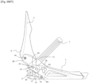
- the Figure 7 illustrates a variant of the first embodiment, which differs from the example given by the Figure 2 in that the axis A1 of rotation of the support shell 3 relative to the base 1 passes through two pivot connections 28 arranged on each of the two hull sides 11. Unlike the previous illustrative examples, the two pivot connections 28 do not form a hinge bearing but only two point connections like rivets.
Landscapes
- Mechanical Control Devices (AREA)
- Footwear And Its Accessory, Manufacturing Method And Apparatuses (AREA)
Claims (7)
- Eine Snowboardbindung mit einer Grundplatte (1), einem relativ zur Grundplatte (1) drehbaren Highback (3), einem Pedal (5) zum Betätigen des Highbacks (3) beim Einsteigen zwischen einer Öffnungs- und einer Schließposition und ein Mittel (15, 16) um die Drehung des Highbacks (3) relativ zur Grundplatte (1) in Schließposition gegen die elastische Rückstellung eines Hebels (13, 13a, 13b) zu blockieren, wobei das Mittel (15) weist zwei Rastkerben (17) auf, dadurch gekennzeichnet, dass sie einen Rastzapfen (21) aufweist, der in eine Gabel (20) des Mittels (15, 16) mit Rastkerben (17) oder des Hebels (13b) eingreift, um das Mittel mit Rastkerben oder den Hebel beim Einsteigen durch Ausrasten des Hebels aus einer der Rastkerben und Einrasten mit der anderen Rastkerbe zu drehen.
- Eine Snowboardbindung nach Anspruch 1, dadurch gekennzeichnet, dass der Rastzapfen (21) an der Grundplatte (1), dem Highback (3) oder dem Pedal (5) montiert ist.
- Eine Snowboardbindung nach Anspruch 2, dadurch gekennzeichnet, dass das Mittel (15) mit Rastkerben (17) aus einem Rad mit einer Aussparung (23) besteht, welche die Gabel (20) zur Aufnahme des Rastzapfens (21) definiert.
- Eine Snowboardbindung nach Anspruch 3, dadurch gekennzeichnet, dass das Rad relativ zum Highback (3) drehbar ist und der Rastzapfen (21) an der Grundplatte (1) montiert ist oder das Rad relativ zur Grundplatte (1) drehbar ist und der Rastzapfen (21) am Highback (3) oder am Pedal (5) montiert ist.
- Eine Snowboardbindung nach Anspruch 2, dadurch gekennzeichnet, dass der Rastzapfen (21) an einer Seite (11) des Highbacks (3) montiert ist.
- Eine Snowboardbindung nach Anspruch 2, dadurch gekennzeichnet, dass der Hebel einen relativ zum Highback (3) drehbaren ersten Arm (13a) und einen mit dem ersten Arm (13a) gelenkig verbundenen und mit den Mitteln (16) mit Rastkerben (17) eingerasteten zweiten Arm (13b) umfasst, der am Highback (3) montiert ist, wobei der erste Arm (13a) eine Aussparung (23) aufweist, die die dem zweiten Arm (13b) gegenüberliegende Gabel definiert, während der Rastzapfen (21) an der Grundplatte (1) montiert ist.
- Eine Snowboardbindung nach Anspruch 6, dadurch gekennzeichnet, dass der erste Arm (13a) des Hebels (13) aus einem an zwei Seiten (11) des tragenden Highbacks (3) angelenkten Bügel besteht.
Applications Claiming Priority (2)
| Application Number | Priority Date | Filing Date | Title |
|---|---|---|---|
| FR2000618A FR3106282A1 (fr) | 2020-01-22 | 2020-01-22 | Fixation de planche des neiges à coque d’appui à plusieurs positions de fermeture déterminées par un moyen de blocage à plusieurs crans |
| PCT/EP2021/051393 WO2021148571A1 (fr) | 2020-01-22 | 2021-01-21 | Fixation de planche des neiges à coque d'appui à plusieurs positions de fermeture déterminées par un moyen de blocage à plusieurs crans |
Publications (2)
| Publication Number | Publication Date |
|---|---|
| EP4486471A1 EP4486471A1 (de) | 2025-01-08 |
| EP4486471B1 true EP4486471B1 (de) | 2025-06-11 |
Family
ID=70918541
Family Applications (1)
| Application Number | Title | Priority Date | Filing Date |
|---|---|---|---|
| EP21701956.1A Active EP4486471B1 (de) | 2020-01-22 | 2021-01-21 | Snowboard-bindung mit einer stützschale, die mehrere schliesspositionen aufweist, die durch eine mehrkerbige verriegelung bestimmt werden |
Country Status (5)
| Country | Link |
|---|---|
| US (1) | US11738253B2 (de) |
| EP (1) | EP4486471B1 (de) |
| CN (1) | CN114867535B (de) |
| FR (1) | FR3106282A1 (de) |
| WO (1) | WO2021148571A1 (de) |
Family Cites Families (17)
| Publication number | Priority date | Publication date | Assignee | Title |
|---|---|---|---|---|
| US5957479A (en) * | 1995-03-02 | 1999-09-28 | Items International, Inc. | Snowboard binding assembly |
| IT1283817B1 (it) * | 1996-08-21 | 1998-04-30 | Pida S R L | Attacco per tavola da neve |
| DE19744613A1 (de) * | 1997-10-09 | 1999-04-15 | Ms Trade Handels Gmbh | Willkürlich schließ- und lösbare Verbindungseinrichtung |
| US6382641B2 (en) * | 1998-05-19 | 2002-05-07 | K-2 Corporation | Snowboard binding system with automatic forward lean support |
| US6196559B1 (en) * | 1998-11-02 | 2001-03-06 | Scott Cress | Snowboot binding |
| EP1314462B1 (de) * | 2001-11-21 | 2005-03-16 | The Burton Corporation | Bindungsträgerplatte für ein Snowboard |
| US6722688B2 (en) * | 2001-11-21 | 2004-04-20 | The Burton Corporation | Snowboard binding system |
| AT412616B (de) * | 2002-02-01 | 2005-05-25 | Atomic Austria Gmbh | Bindungseinrichtung für sportgeräte, insbesondere für ein snowboard |
| CN100571825C (zh) * | 2005-02-04 | 2009-12-23 | 罗特费尔拉公司 | 越野滑雪或旋转滑雪的滑雪板固定器 |
| US20070182130A1 (en) | 2006-02-06 | 2007-08-09 | Laser Brian K | Snowboard binding |
| CN101502713A (zh) * | 2009-03-04 | 2009-08-12 | 穆吉利 | 滑雪板脚部固定器 |
| DE202015009508U1 (de) * | 2014-03-19 | 2018-01-15 | Madshus As | Mechanismus zum Verriegeln einer Skibindung in der Längsrichtung auf einer Begfestigungsplatte |
| GB2526607A (en) * | 2014-05-29 | 2015-12-02 | Pierre Mendelsohn | Step-in / step-out snowboard binding system |
| US9545560B2 (en) * | 2014-12-22 | 2017-01-17 | Helos, Llc | Heel locking binding system |
| US10561926B2 (en) * | 2018-03-21 | 2020-02-18 | Paul Flannery | Step-in snowboard binding |
| CN108686365B (zh) * | 2018-07-18 | 2025-01-14 | 广州市勇源运动用品科技有限公司 | 一种越野滑雪板固定装置 |
| EP3741436B1 (de) * | 2019-05-24 | 2024-10-09 | Skis Rossignol | Bindungsvorrichtung zur befestigung eines snowboardschuhs auf einem snowboard |
-
2020
- 2020-01-22 FR FR2000618A patent/FR3106282A1/fr not_active Ceased
-
2021
- 2021-01-21 WO PCT/EP2021/051393 patent/WO2021148571A1/fr not_active Ceased
- 2021-01-21 CN CN202180007444.6A patent/CN114867535B/zh active Active
- 2021-01-21 US US17/786,106 patent/US11738253B2/en active Active
- 2021-01-21 EP EP21701956.1A patent/EP4486471B1/de active Active
Also Published As
| Publication number | Publication date |
|---|---|
| FR3106282A1 (fr) | 2021-07-23 |
| WO2021148571A1 (fr) | 2021-07-29 |
| CN114867535B (zh) | 2026-03-10 |
| CN114867535A (zh) | 2022-08-05 |
| US20230022644A1 (en) | 2023-01-26 |
| EP4486471A1 (de) | 2025-01-08 |
| US11738253B2 (en) | 2023-08-29 |
Similar Documents
| Publication | Publication Date | Title |
|---|---|---|
| EP2944361B1 (de) | Tourenskibindung | |
| EP3135350B1 (de) | Bremsvorrichtung zum befestigen eines snowboards | |
| EP2486817B1 (de) | Sportschuh mit angelenktem Schaft für eine Laufstellung | |
| EP2399654A1 (de) | Sicherheitsbefestigung für den Skitourensport | |
| FR2636578A1 (fr) | Dispositif de reglage d'orientation pour projecteur de vehicule automobile | |
| EP0250293B1 (de) | Steuerungssystem einer beweglichen aerodynamischen Fläche eines Flugzeuges | |
| WO1996003185A1 (fr) | Dispositif de fixation d'une chaussure sur un surf a neige | |
| EP4486471B1 (de) | Snowboard-bindung mit einer stützschale, die mehrere schliesspositionen aufweist, die durch eine mehrkerbige verriegelung bestimmt werden | |
| EP4292681B1 (de) | Vorrichtung zum halten eines schuhs auf einem gleitbrett und gleitbrett mit einer solchen vorrichtung | |
| EP3785772B1 (de) | Haltevorrichtungen für gleitbrett | |
| EP2455142A1 (de) | Haltevorrichtung, die einen reversiblen Verriegelungsmechanismus eines Verankerungselementes eines Schuh enthält | |
| FR2918142A1 (fr) | Dispositif d'assistance a l'actionnement d'une pedale d'embrayage. | |
| WO2020020798A1 (fr) | Fixation de planche des neiges comprenant une pedale de commande portee par des bras mobiles rotation sur la coque d'appui | |
| EP3511057B1 (de) | Sicherheitsbindung für einen schuh auf einem ski und einen ski mit dieser sicherheitsbindung | |
| CH690899A5 (fr) | Dispositif de fixation d'une chaussure sur une planche à neige. | |
| EP0332546B1 (de) | Bindung eines Schuhs auf einen Langlaufski | |
| EP0611671B1 (de) | Steuergerät für manuelle und automatische Regelung der Fahrzeughöhe in einem Kraftfahrzeug mit hydropneumatischer Aufhängung | |
| EP1973012A2 (de) | Uhr mit Kinematik zum Ausgleich des Spiels des Aufziehkranzes, der in die Ruhe- oder Aufziehposition versetzt wird | |
| EP3184155B1 (de) | Skibindung | |
| EP1721641B1 (de) | Bindungsvorrichtung mit einstellbarer Rückhubenergie | |
| EP1319424A1 (de) | Bindungsanlage für ein Schuh an ein Sportgerät ohne Hebung | |
| EP0739646A1 (de) | Bindungssystem für Schuhe auf Skis | |
| FR2850914A1 (fr) | Siege de vehicule comportant un dossier rabattable vers l'avant | |
| EP4414792A1 (de) | Korrekturmechanismus für mindestens eine erste und zweite anzeigevorrichtung einer uhr | |
| EP3829014A1 (de) | Gerät mit einer kippbaren gerätehalterung und einem verriegelungssystem, das mittels eines kippbaren betätigungsknopfes entriegelt werden kann |
Legal Events
| Date | Code | Title | Description |
|---|---|---|---|
| STAA | Information on the status of an ep patent application or granted ep patent |
Free format text: STATUS: UNKNOWN |
|
| STAA | Information on the status of an ep patent application or granted ep patent |
Free format text: STATUS: THE INTERNATIONAL PUBLICATION HAS BEEN MADE |
|
| PUAI | Public reference made under article 153(3) epc to a published international application that has entered the european phase |
Free format text: ORIGINAL CODE: 0009012 |
|
| STAA | Information on the status of an ep patent application or granted ep patent |
Free format text: STATUS: REQUEST FOR EXAMINATION WAS MADE |
|
| 17P | Request for examination filed |
Effective date: 20220711 |
|
| AK | Designated contracting states |
Kind code of ref document: A1 Designated state(s): AL AT BE BG CH CY CZ DE DK EE ES FI FR GB GR HR HU IE IS IT LI LT LU LV MC MK MT NL NO PL PT RO RS SE SI SK SM TR |
|
| GRAP | Despatch of communication of intention to grant a patent |
Free format text: ORIGINAL CODE: EPIDOSNIGR1 |
|
| STAA | Information on the status of an ep patent application or granted ep patent |
Free format text: STATUS: GRANT OF PATENT IS INTENDED |
|
| INTG | Intention to grant announced |
Effective date: 20250116 |
|
| GRAS | Grant fee paid |
Free format text: ORIGINAL CODE: EPIDOSNIGR3 |
|
| GRAA | (expected) grant |
Free format text: ORIGINAL CODE: 0009210 |
|
| STAA | Information on the status of an ep patent application or granted ep patent |
Free format text: STATUS: THE PATENT HAS BEEN GRANTED |
|
| AK | Designated contracting states |
Kind code of ref document: B1 Designated state(s): AL AT BE BG CH CY CZ DE DK EE ES FI FR GB GR HR HU IE IS IT LI LT LU LV MC MK MT NL NO PL PT RO RS SE SI SK SM TR |
|
| REG | Reference to a national code |
Ref country code: GB Ref legal event code: FG4D Free format text: NOT ENGLISH |
|
| REG | Reference to a national code |
Ref country code: CH Ref legal event code: EP |
|
| REG | Reference to a national code |
Ref country code: IE Ref legal event code: FG4D Free format text: LANGUAGE OF EP DOCUMENT: FRENCH |
|
| REG | Reference to a national code |
Ref country code: DE Ref legal event code: R096 Ref document number: 602021032081 Country of ref document: DE |
|
| P01 | Opt-out of the competence of the unified patent court (upc) registered |
Free format text: CASE NUMBER: APP_29491/2025 Effective date: 20250620 |
|
| PG25 | Lapsed in a contracting state [announced via postgrant information from national office to epo] |
Ref country code: FI Free format text: LAPSE BECAUSE OF FAILURE TO SUBMIT A TRANSLATION OF THE DESCRIPTION OR TO PAY THE FEE WITHIN THE PRESCRIBED TIME-LIMIT Effective date: 20250611 Ref country code: ES Free format text: LAPSE BECAUSE OF FAILURE TO SUBMIT A TRANSLATION OF THE DESCRIPTION OR TO PAY THE FEE WITHIN THE PRESCRIBED TIME-LIMIT Effective date: 20250611 |
|
| REG | Reference to a national code |
Ref country code: LT Ref legal event code: MG9D |
|
| PG25 | Lapsed in a contracting state [announced via postgrant information from national office to epo] |
Ref country code: GR Free format text: LAPSE BECAUSE OF FAILURE TO SUBMIT A TRANSLATION OF THE DESCRIPTION OR TO PAY THE FEE WITHIN THE PRESCRIBED TIME-LIMIT Effective date: 20250912 Ref country code: NO Free format text: LAPSE BECAUSE OF FAILURE TO SUBMIT A TRANSLATION OF THE DESCRIPTION OR TO PAY THE FEE WITHIN THE PRESCRIBED TIME-LIMIT Effective date: 20250911 |
|
| REG | Reference to a national code |
Ref country code: NL Ref legal event code: MP Effective date: 20250611 |
|
| PG25 | Lapsed in a contracting state [announced via postgrant information from national office to epo] |
Ref country code: BG Free format text: LAPSE BECAUSE OF FAILURE TO SUBMIT A TRANSLATION OF THE DESCRIPTION OR TO PAY THE FEE WITHIN THE PRESCRIBED TIME-LIMIT Effective date: 20250611 |
|
| PG25 | Lapsed in a contracting state [announced via postgrant information from national office to epo] |
Ref country code: HR Free format text: LAPSE BECAUSE OF FAILURE TO SUBMIT A TRANSLATION OF THE DESCRIPTION OR TO PAY THE FEE WITHIN THE PRESCRIBED TIME-LIMIT Effective date: 20250611 |
|
| PG25 | Lapsed in a contracting state [announced via postgrant information from national office to epo] |
Ref country code: RS Free format text: LAPSE BECAUSE OF FAILURE TO SUBMIT A TRANSLATION OF THE DESCRIPTION OR TO PAY THE FEE WITHIN THE PRESCRIBED TIME-LIMIT Effective date: 20250911 |
|
| PG25 | Lapsed in a contracting state [announced via postgrant information from national office to epo] |
Ref country code: LV Free format text: LAPSE BECAUSE OF FAILURE TO SUBMIT A TRANSLATION OF THE DESCRIPTION OR TO PAY THE FEE WITHIN THE PRESCRIBED TIME-LIMIT Effective date: 20250611 |
|
| PG25 | Lapsed in a contracting state [announced via postgrant information from national office to epo] |
Ref country code: NL Free format text: LAPSE BECAUSE OF FAILURE TO SUBMIT A TRANSLATION OF THE DESCRIPTION OR TO PAY THE FEE WITHIN THE PRESCRIBED TIME-LIMIT Effective date: 20250611 |
|
| PG25 | Lapsed in a contracting state [announced via postgrant information from national office to epo] |
Ref country code: PT Free format text: LAPSE BECAUSE OF FAILURE TO SUBMIT A TRANSLATION OF THE DESCRIPTION OR TO PAY THE FEE WITHIN THE PRESCRIBED TIME-LIMIT Effective date: 20251013 |
|
| PG25 | Lapsed in a contracting state [announced via postgrant information from national office to epo] |
Ref country code: IS Free format text: LAPSE BECAUSE OF FAILURE TO SUBMIT A TRANSLATION OF THE DESCRIPTION OR TO PAY THE FEE WITHIN THE PRESCRIBED TIME-LIMIT Effective date: 20251011 |
|
| PG25 | Lapsed in a contracting state [announced via postgrant information from national office to epo] |
Ref country code: SM Free format text: LAPSE BECAUSE OF FAILURE TO SUBMIT A TRANSLATION OF THE DESCRIPTION OR TO PAY THE FEE WITHIN THE PRESCRIBED TIME-LIMIT Effective date: 20250611 |
|
| PG25 | Lapsed in a contracting state [announced via postgrant information from national office to epo] |
Ref country code: CZ Free format text: LAPSE BECAUSE OF FAILURE TO SUBMIT A TRANSLATION OF THE DESCRIPTION OR TO PAY THE FEE WITHIN THE PRESCRIBED TIME-LIMIT Effective date: 20250611 |
|
| PG25 | Lapsed in a contracting state [announced via postgrant information from national office to epo] |
Ref country code: PL Free format text: LAPSE BECAUSE OF FAILURE TO SUBMIT A TRANSLATION OF THE DESCRIPTION OR TO PAY THE FEE WITHIN THE PRESCRIBED TIME-LIMIT Effective date: 20250611 |
|
| PG25 | Lapsed in a contracting state [announced via postgrant information from national office to epo] |
Ref country code: EE Free format text: LAPSE BECAUSE OF FAILURE TO SUBMIT A TRANSLATION OF THE DESCRIPTION OR TO PAY THE FEE WITHIN THE PRESCRIBED TIME-LIMIT Effective date: 20250611 |
|
| PG25 | Lapsed in a contracting state [announced via postgrant information from national office to epo] |
Ref country code: SK Free format text: LAPSE BECAUSE OF FAILURE TO SUBMIT A TRANSLATION OF THE DESCRIPTION OR TO PAY THE FEE WITHIN THE PRESCRIBED TIME-LIMIT Effective date: 20250611 |
|
| REG | Reference to a national code |
Ref country code: CH Ref legal event code: U11 Free format text: ST27 STATUS EVENT CODE: U-0-0-U10-U11 (AS PROVIDED BY THE NATIONAL OFFICE) Effective date: 20260225 |
|
| REG | Reference to a national code |
Ref country code: DE Ref legal event code: R097 Ref document number: 602021032081 Country of ref document: DE |
|
| PG25 | Lapsed in a contracting state [announced via postgrant information from national office to epo] |
Ref country code: DK Free format text: LAPSE BECAUSE OF FAILURE TO SUBMIT A TRANSLATION OF THE DESCRIPTION OR TO PAY THE FEE WITHIN THE PRESCRIBED TIME-LIMIT Effective date: 20250611 |
|
| PGFP | Annual fee paid to national office [announced via postgrant information from national office to epo] |
Ref country code: DE Payment date: 20260109 Year of fee payment: 6 |
|
| PGFP | Annual fee paid to national office [announced via postgrant information from national office to epo] |
Ref country code: AT Payment date: 20260109 Year of fee payment: 6 |
|
| PG25 | Lapsed in a contracting state [announced via postgrant information from national office to epo] |
Ref country code: IT Free format text: LAPSE BECAUSE OF FAILURE TO SUBMIT A TRANSLATION OF THE DESCRIPTION OR TO PAY THE FEE WITHIN THE PRESCRIBED TIME-LIMIT Effective date: 20250611 |
|
| PLBE | No opposition filed within time limit |
Free format text: ORIGINAL CODE: 0009261 |
|
| STAA | Information on the status of an ep patent application or granted ep patent |
Free format text: STATUS: NO OPPOSITION FILED WITHIN TIME LIMIT |
|
| PGFP | Annual fee paid to national office [announced via postgrant information from national office to epo] |
Ref country code: FR Payment date: 20260108 Year of fee payment: 6 |
|
| PGFP | Annual fee paid to national office [announced via postgrant information from national office to epo] |
Ref country code: CH Payment date: 20260225 Year of fee payment: 6 |
|
| REG | Reference to a national code |
Ref country code: CH Ref legal event code: L10 Free format text: ST27 STATUS EVENT CODE: U-0-0-L10-L00 (AS PROVIDED BY THE NATIONAL OFFICE) Effective date: 20260423 |