EP4487687B1 - Dispositif et procédé de séparation de morceaux de pâte - Google Patents
Dispositif et procédé de séparation de morceaux de pâte Download PDFInfo
- Publication number
- EP4487687B1 EP4487687B1 EP23183391.4A EP23183391A EP4487687B1 EP 4487687 B1 EP4487687 B1 EP 4487687B1 EP 23183391 A EP23183391 A EP 23183391A EP 4487687 B1 EP4487687 B1 EP 4487687B1
- Authority
- EP
- European Patent Office
- Prior art keywords
- shaft
- dough
- driver element
- speed
- conveying
- Prior art date
- Legal status (The legal status is an assumption and is not a legal conclusion. Google has not performed a legal analysis and makes no representation as to the accuracy of the status listed.)
- Active
Links
Images


Classifications
-
- A—HUMAN NECESSITIES
- A21—BAKING; EDIBLE DOUGHS
- A21C—MACHINES OR EQUIPMENT FOR MAKING OR PROCESSING DOUGHS; HANDLING BAKED ARTICLES MADE FROM DOUGH
- A21C9/00—Other apparatus for handling dough or dough pieces
- A21C9/08—Depositing, arranging and conveying apparatus for handling pieces, e.g. sheets of dough
- A21C9/085—Separating, spacing, orienting or aligning discrete dough pieces, e.g. after passing a cutting device
-
- B—PERFORMING OPERATIONS; TRANSPORTING
- B65—CONVEYING; PACKING; STORING; HANDLING THIN OR FILAMENTARY MATERIAL
- B65G—TRANSPORT OR STORAGE DEVICES, e.g. CONVEYORS FOR LOADING OR TIPPING, SHOP CONVEYOR SYSTEMS OR PNEUMATIC TUBE CONVEYORS
- B65G47/00—Article or material-handling devices associated with conveyors; Methods employing such devices
- B65G47/22—Devices influencing the relative position or the attitude of articles during transit by conveyors
- B65G47/26—Devices influencing the relative position or the attitude of articles during transit by conveyors arranging the articles, e.g. varying spacing between individual articles
- B65G47/30—Devices influencing the relative position or the attitude of articles during transit by conveyors arranging the articles, e.g. varying spacing between individual articles during transit by a series of conveyors
- B65G47/32—Applications of transfer devices
-
- B—PERFORMING OPERATIONS; TRANSPORTING
- B65—CONVEYING; PACKING; STORING; HANDLING THIN OR FILAMENTARY MATERIAL
- B65G—TRANSPORT OR STORAGE DEVICES, e.g. CONVEYORS FOR LOADING OR TIPPING, SHOP CONVEYOR SYSTEMS OR PNEUMATIC TUBE CONVEYORS
- B65G47/00—Article or material-handling devices associated with conveyors; Methods employing such devices
- B65G47/74—Feeding, transfer, or discharging devices of particular kinds or types
- B65G47/82—Rotary or reciprocating members for direct action on articles or materials, e.g. pushers, rakes, shovels
Definitions
- the invention relates to a device and a method for separating dough pieces resting on a conveyor device. Furthermore, the present invention relates to a system comprising such a device.
- a preferably pre-calibrated dough is usually punched or cut into individual pieces.
- these pieces e.g., by rolling them up, it is advantageous if the distance between the pieces can be increased.
- the JP 2000-316463 A describes a device for separating dough pieces.
- the device has two conveyor belts that run at different speeds, with a rotating shaft located above the two conveyor belts in the transition area, which The dough pieces conveyed by the conveyor belts are picked up from above and moved from the first conveyor belt to the second conveyor belt.
- the US 5,634,549 B2 discloses a device for conveying and sorting objects, in particular a device for increasing the number of rows of objects on a conveyor device.
- the device comprises a separating element, in particular a rotating separating element with a shaft from which several paddles protrude.
- the device also has a rotating displacement element, which is arranged downstream of the separating element in the conveying direction.
- the objects are arranged at defined intervals by the separating element and then fed to the displacement element, which deflects the objects to defined positions next to one another.
- the paddles of the separating element are arranged at regular angular intervals on the shaft and are mounted radially displaceable relative to the shaft against a spring force in the direction of the shaft's rotational axis.
- the displacement element has a shaft with spokes protruding radially from it.
- the shaft of the displacement element has a lower rotational speed than the conveyor device, so that the spokes get in the way of the objects, whereby the objects are pushed aside by the spokes.
- the EP 0 284 835 B1 describes a method and a device for aligning irregularly spaced confectionery pieces on a conveyor belt.
- the device comprises a plurality of crossbars extending from a rotatable shaft arranged above the conveyor belt. These crossbars decelerate the confectionery pieces on the conveyor belt until the offset of the confectionery pieces in a row is eliminated. The spacing of the rows of confectionery and their offset can be measured, and the rotation of the shaft with the crossbars can be controlled according to the measured data.
- the object of the invention is to create a device belonging to the technical field mentioned at the outset, which ensures a reliable separation of dough pieces and which is as simple as possible to construct and maintain.
- the device for separating dough pieces comprises a first conveyor device and an adjoining second conveyor device, on which dough pieces resting thereon can be conveyed in a conveying direction.
- the first conveyor device is driven at a first speed and the second conveyor device is driven at a second speed that is greater than the first speed.
- the device has a shaft arranged at a first distance above the transition region between the first conveyor device and the second conveyor device, which shaft can be set into a rotary movement about a longitudinal axis at a third speed that is greater than the first speed by means of a drive.
- the shaft extends in a direction transverse to the conveying direction across the entire width of the two conveyor devices, wherein at least one driver element projecting radially therefrom is arranged on the shaft and has a contact surface at a free end that is spaced from a surface of the shaft.
- the at least one driver element is mounted radially relative to the shaft and is freely displaceable thereon, so that the contact surface of the at least one driver element moves radially toward or away from the shaft as a result of the rotational movement of the shaft about the longitudinal axis as a result of gravity and the dead weight of the at least one driver element.
- the at least one driver element has a dimension such that the contact surface can rest on a piece of dough resting on the first conveyor device in order to push it from the first conveyor device to the second conveyor device at the third speed.
- the device according to the invention has few moving parts, so that it is essentially maintenance-free and can be cleaned very easily. Such a device therefore has low operating costs and can also be manufactured and operated simply and inexpensively.
- the pressure applied to the dough piece can be acting force must be minimized so that the piece of dough is not deformed as much as possible by the contact surface resting on it.
- Separating dough pieces is understood here as increasing the distance between adjacent dough pieces in the conveying direction. In the device according to the invention, the separation therefore increases the distance between adjacent dough pieces in the conveying direction.
- a dough piece is understood to be a piece punched or cut from calibrated dough, i.e., dough made to a predetermined thickness, which may have any shape, such as triangular, square, round, oval, or polygonal.
- the dough pieces are preferably produced beforehand using a punching tool, a drop knife, or a cutting roller, in particular using a cutting or punching tool positioned upstream of the device in the conveying direction.
- dough refers to a mixture of at least one flour with at least one liquid, as well as dough-like masses, such as marzipan or nut masses.
- the dough pieces separated by the device according to the invention can consist, in particular, of puff pastry, sponge cake dough, filo dough, yeast dough, shortcrust pastry, etc., or even pasta dough.
- the first conveyor device and the second conveyor device are preferably designed as belt conveyors.
- the conveyor devices can also be designed differently, for example as link conveyors.
- Conveyor belts or link conveyors have an endless belt, which is deflected at the ends by rollers by essentially 180°. Accordingly, such conveyor devices have an upper part and a lower part, which each move in opposite directions.
- the conveying direction refers to that part of the conveyor device on which the dough pieces can rest, accordingly usually on the upper part of the conveyor device or, in the preferred version, on the upper part of the endless belt.
- Each of the two conveyors has a conveyor drive that can be used to drive the conveyors at the first and second speeds, respectively.
- a single conveyor drive can be used for both conveyors, with the different speeds being achieved using at least one gear.
- the first conveyor device and the second conveyor device are preferably arranged such that they have the same height. This means that there is no difference in height between the first conveyor device and the second conveyor device in the transition area. As a result, the dough pieces do not have to overcome any difference in height when being pushed from the first conveyor device to the second conveyor device.
- the second conveyor device can be arranged lower relative to the first conveyor device.
- the height specification refers to the part of the endless belt on which the dough pieces can rest, i.e. generally the upper part of the endless belt.
- the two conveying devices preferably have the same width transverse to the conveying direction.
- the shaft is arranged at a first distance above a transition area between the first conveyor device and the second conveyor device. This means in an area that is located above a rear end of the first conveyor device in the conveying direction and a front end of the second conveyor device in the conveying direction.
- the second conveyor device is preferably flush with the first conveyor device, which means that the gap or distance between the two conveyor devices is as small as possible.
- the longitudinal axis of the shaft is preferably arranged above this gap or distance.
- the first distance is selected such that the dough pieces can be pushed through between the conveyor devices and the shaft. This means that the distance is selected such that it is greater than the thickness of the dough pieces.
- the drive of the shaft is preferably a rotary drive, in particular an electric motor, such as a servo motor or a stepper motor, or a pneumatic motor.
- An output of the rotary drive can be connected either directly to the shaft or indirectly via a gear.
- the shaft is set in rotation by the drive in such a way that the part of the shaft directed toward the first conveying device moves in the conveying direction.
- the shaft drive has adjustment means or a control system with which the third speed of the shaft's rotational movement can be adjusted.
- the third speed corresponds to the second speed.
- the third speed can be greater or less than the second speed.
- the third speed is always greater than the first speed.
- the second speed is higher than the first speed ensures that the separation of the dough pieces, i.e. the increase in their distances in the conveying direction on the second conveyor, is maintained.
- the at least one driver element can be designed as a closed surface or, alternatively, as a substantially U-shaped bracket.
- the at least one driver element and its contact surface are preferably made of a food-safe material, in particular a metal or a plastic.
- the at least one driver element is preferably formed as a single piece.
- the at least one driver element can also consist of several interconnected parts, which are either all made of the same material or of different materials. In the case of a driver element consisting of several parts, the parts are preferably connected to one another in a material-to-material manner, e.g., by welding, so that as little dough residue as possible remains between the parts and cleaning of the at least one driver element is as easy as possible.
- the at least one driver element protrudes radially from the shaft. More than one driver element can be arranged on the shaft, in particular two, three, four, or more driver elements. If more than one driver element is arranged on the shaft, all driver elements are preferably of identical design. Preferably, the at least one driver element is detachably arranged on the shaft, for example, so that it can be removed from the shaft in the event of wear or damage, or for cleaning.
- the at least one driver element preferably extends substantially along the entire length of the shaft, i.e., substantially along the entire longitudinal axis of the shaft.
- the free end of the at least one driver element is the end that is spaced from a surface of the shaft and thus also from its longitudinal axis. This free end of the at least one driver element is, in particular, in the form of a side edge of the at least one driver element.
- the contact surface of the at least one driver element is designed to rest on at least one piece of dough resting on the first conveyor device.
- the contact surface preferably has no sharp edges in order to prevent deformation of the piece of dough.
- the contact surface is therefore preferably essentially flat and/or has rounded longitudinal edges.
- the contact surface preferably has a width in the conveying direction that is large enough to slide over the first conveyor device onto a piece of dough on which the contact surface rests.
- the contact surface is preferably made of a material that has the greatest possible static friction on the dough pieces, in particular a polymer.
- the contact surface can be formed integrally with the at least one driver element or can be present as a separate part that is connected to the driver element.
- the at least one driver element is mounted so as to be freely displaceable in the radial direction relative to the shaft. This means that the at least one driver element can be displaced relative to the shaft without the influence of any kind of force - with the exception of gravity. This results in the contact surface of the at least one driver element being moved either away from or towards the shaft due to gravity and the dead weight of the at least one driver element, depending on the radial position of the at least one driver element around the longitudinal axis of the shaft (which is set in rotation by the drive). This means that when the at least one driver element moves towards the first conveyor device, the contact surface moves away from the shaft and towards the first conveyor device due to gravity.
- the contact surface to be moved, from a certain radial position of the at least one driver element around the longitudinal axis of the shaft towards the first conveyor device, and its contact surface to come into contact with a piece of dough lying on the first conveyor device.
- the at least one driver element which is moved at the third speed of the shaft, which is higher than the first speed of the first conveyor, can move the piece of dough on the first conveyor at the third speed and push it onto the second conveyor.
- the contact surface of the at least one driver element has at least one element which increases the static friction with the piece of dough compared to the second conveying device or is made of a material which has a higher static friction with the piece of dough than the first conveying device.
- the materials of the contact surface of the at least one driver element and of the first conveying device are matched to one another so that the contact surface has a higher static friction with the piece of dough than the first conveying device and preferably also than the second conveying device.
- the at least one driver element forms a positive connection when its contact surface comes into contact with the piece of dough, since the contact surface is slightly pressed into the piece of dough.
- the at least one driver element is freely movable radially relative to the shaft, the height difference resulting from the contact surface of the at least one driver element resting on the piece of dough is automatically compensated.
- the at least one driver element and/or the shaft preferably has a retaining element that prevents the at least one driver element from falling off the shaft. This means that the retaining element limits the movement of the at least one driver element away from the shaft, preventing it from becoming detached from the shaft.
- the at least one carrier element can rest with its support surface on more than one piece of dough at the same time, for example on two or more pieces of dough which lie next to each other in a line on the first conveyor in order to push them simultaneously over the first conveyor.
- a line refers to an arrangement of two or more dough pieces next to each other transversely to the conveying direction.
- a row refers to dough pieces arranged one behind the other in several lines in the conveying direction.
- the shaft preferably has two or more drive elements arranged on the shaft at a radial distance of 360°/n relative to one another, where n represents the number of drive elements on the shaft.
- the at least one driver element is mounted on the shaft by means of at least one plain bearing.
- a plain bearing can be implemented, for example, by means of at least one groove in the shaft, in which the at least one driver element is displaceably mounted.
- the groove and/or the at least one driver element received therein preferably have a sliding coating.
- the at least one driver element can also be mounted on the shaft in a radially displaceable manner by means of another bearing, for example a rolling bearing.
- the shaft preferably has an even number of driver elements, wherein driver elements arranged on the shaft at a radial distance of 180° relative to one another are connected to one another via at least two connecting webs which are located in the region of the ends of the respective driver elements, wherein each of the connecting webs is received in a sliding guide of the shaft.
- the drive elements arranged opposite one another on the shaft are mechanically connected by at least two connecting webs.
- the weight of the two drive elements acts on the contact surface of one of the two drive elements resting on a piece of dough, so that the static friction between the contact surface of one drive element resting on a piece of dough is greater than in an embodiment that has only one drive element or in which two or more drive elements are not connected to one another.
- the device has a control system which controls the drive of the shaft in such a way that the shaft performs a rotational movement around its longitudinal axis at an angle of 360°/n at predefined time intervals, where n represents the number of driver elements arranged on the shaft.
- the controller preferably has input means with which the predefined time intervals can be set or changed.
- the controller is preferably additionally connected to a drive of the first conveyor device and/or the second conveyor device.
- the first speed and/or the second speed can preferably be set or changed by means of the controller, for example via the input means.
- the predefined time intervals are preferably equal, which means that the shaft periodically performs a rotational movement through an angle of 360°/n.
- the predefined time intervals are preferably adapted to the size of the dough pieces lying on the first conveyor device as well as to the first and second speeds, so that for each rotational movement through an angle of 360°/n, one dough piece or a line of dough pieces lying next to one another transversely to the conveying direction can be pushed from the first conveyor device to the second conveyor device by means of the contact surface of the at least one driver element.
- the control can preferably be designed in such a way that it calculates the predefined time intervals based on the first and third speeds and the size of the dough pieces lying on the first conveyor device.
- control system is configured such that, in a rest position in which the shaft is stationary, the at least one driver element is aligned such that its contact surface does not come into contact with a piece of dough resting on the first conveyor device or the second conveyor device.
- the driver element or the two driver elements are preferably substantially parallel to the first and second conveyor devices.
- the predefined time intervals can preferably be determined based on data from a sensor connected to the controller, which can detect the position of dough pieces or lines of dough pieces resting on the first conveyor. This allows for reliable operation of the device, since dough pieces or lines of dough pieces resting on the first conveyor at irregular intervals in the conveying direction can be pushed onto the second conveyor by means of the contact surface of the at least one driver element.
- the device is designed such that the contact surface of the at least one driver element comes to rest at a predefined position on a piece of dough resting on the first conveying device.
- the predefined position is preferably the center of a piece of dough resting on the first conveyor device.
- the predefined position can also be in the first third of a piece of dough resting on the conveyor device in the conveying direction.
- Several pieces of dough resting next to each other in a line on the first conveyor device are generally aligned substantially the same, i.e., their front and rear edges, viewed in the conveying direction, lie substantially on the same imaginary line.
- the contact surface of the at least one driver element rests in essentially the same position for all dough pieces in the line.
- the controller is further preferably configured to calculate the predefined time intervals based on the first speed, the third speed, and the size of the dough pieces such that the contact surface of the at least one driver element rests at the predefined position.
- the controller also has means with which at least the position of a first dough piece resting on the first conveyor device or of a first line of dough pieces resting on the first conveyor device can be detected. This can be implemented either by manual input by a user, via at least one sensor, or via data communication with a dough processing unit, for example a punching or cutting unit, arranged upstream of the shaft in the conveying direction.
- the device preferably has adjustment means with which the first distance can be changed.
- the adjustment means can enable a manual or motorized change of the first distance.
- the adjustment means can therefore comprise, for example, at least one adjusting screw, at least one spindle, and/or at least one actuator, such as a pneumatic or hydraulic piston or an electric motor.
- the shaft is connected to the drive via a detachable connection, in particular via a detachable coupling.
- a detachable connection in particular via a detachable coupling.
- This allows for easy cleaning of the shaft and the at least one driver element, since the shaft can be detached from the device and moved to a cleaning location.
- This also allows for easy replacement of the shaft, for example, in the event of damage or if a shaft with at least one driver element with a larger or smaller dimension is to be used.
- an adjusting element is arranged on the shaft, with which the radial movement of the at least one driver element in the radial direction away from the surface of the shaft can be limited to at least two predetermined values.
- the adjusting element is preferably arranged on the shaft so as to be linearly displaceable in the axial direction and has at least two stop surfaces which are arranged at different distances from the surface of the shaft and on which a stop area arranged on at least one driver element and opposite the contact surface can be brought into abutment.
- the stop surface suitable for the dough pieces to be moved can be selected, which should interact with the stop area.
- the present application further relates to a method for separating dough pieces.
- a first step at least one piece of dough is conveyed on a first conveyor device in a conveying direction at a first speed.
- a shaft arranged at a first distance above a transition region between the first conveyor device and a second conveyor device following it in the conveying direction is set in rotation by means of a drive at a third speed that is higher than the first speed.
- At least one driver element projecting radially from the shaft is arranged on the shaft. At a free end spaced from a surface of the shaft, the driver element has a contact surface and is mounted so as to be freely displaceable in the radial direction relative to the shaft and on the shaft.
- the second conveyor device is driven in the conveying direction at a second speed that is higher than the first speed.
- at least one piece of dough is guided by the at least one driver element by resting its contact surface against the shaft. on it. Subsequently, the at least one piece of dough is pushed by the contact surface resting on it with the at least one driver element during the rotational movement of the shaft, so that the at least one piece of dough is pushed from the first conveying device to the second conveying device at the third speed.
- the distances between dough pieces lying one behind the other in the conveying direction can be increased, i.e. the dough pieces can be reliably separated.
- the method described above is particularly preferably carried out using a device according to the invention as described above. Accordingly, the method can preferably be used with a device that comprises at least one or a combination of two or more of the described, preferred features as described above.
- the third speed is preferably the same as the second speed.
- the third speed can be higher or lower than the third speed.
- the third speed is always higher than the first speed.
- the present application further relates to a system for producing dough pieces, comprising at least one unit for punching or cutting dough pieces from a dough and a device for separating dough pieces according to the above description, which is arranged in the conveying direction downstream of the unit for punching or cutting dough pieces from a dough.
- the unit for punching or cutting dough pieces from a dough is preferably in the form of a cutting roller, a punching unit with at least one punching die, a drop knife or the like.
- the system may further comprise at least one further unit, which is arranged either upstream or downstream of the device for separating dough pieces in the conveying direction.
- a further unit may include, for example, a rotating unit for rotating individual lines of dough pieces, a filling unit for applying a filling to the dough pieces, a longitudinal cutting unit for cutting at least one piece of dough into strips, or a unit for winding the dough pieces.
- the Fig. 1 shows a schematic side view of an embodiment of a device 1 according to the invention for separating dough pieces 5.1 - 5.3.
- the device 1 comprises a first conveyor device 2, which in the embodiment shown is designed as a belt conveyor. Dough pieces 5.1 - 5.3 can rest on the first conveyor device 2 and are conveyed by the first conveyor device 2 at a first speed in a conveying direction 4.
- the device 1 further comprises a second conveyor device 3, which in the embodiment shown is also designed as a belt conveyor.
- the second conveyor device 3 is arranged behind the first conveyor device 2 in the conveying direction 4, with the two conveyor devices 2, 3 being arranged essentially at the same height.
- the mutually facing ends of the two conveyor devices 2, 3 lie close to one another in a transition region U, so that the dough pieces 5.1 - 5.3 conveyed on the first conveyor device 2 can be transferred from the first conveyor device 2 to the second conveyor device 3.
- the dough pieces 5.1 - 5.3 can be conveyed in the conveying direction 4 at a second speed which is higher than the first speed.
- the device has a shaft 6, which is arranged at a first distance A above the two conveyor devices 2, 3 in the transition area U.
- the shaft 6 extends transversely to the conveying direction 4 over an entire width of the two conveying devices 2, 3 and has a longitudinal axis 8.
- the first distance A can be changed via adjusting means 30, so that a suitable first distance A can be set depending on the thickness of the dough pieces 5.1 - 5.3.
- the shaft 6 is set in rotational movement 7 about its longitudinal axis 8 via a drive 19.
- the rotational movement 7 occurs at a third speed, which is higher than the first speed and preferably the same as the second speed.
- the direction of the rotational movement 7 is such that the part of the shaft 6 facing the conveying devices 2, 3 moves in the conveying direction 4.
- two driver elements 9.1, 9.2 projecting radially from the shaft 6 are arranged on the shaft.
- a different number of driver elements 9.1, 9.2 can be arranged on the shaft 6, for example just one or three.
- the driver elements 9.1, 9.2 each have a contact surface 10.1, 10.2 at a free end that is spaced from the shaft 6, i.e., directed away from it.
- the drive elements 9.1, 9.2 are mounted on the shaft 6 so that they can move freely in the radial direction relative to the shaft 6 (indicated by a double arrow). This means that the drive elements 9.1, 9.2 can be moved in the radial direction relative to the shaft 6 without the influence of any force - with the exception of gravity. Since the shaft 6 is set in rotation 7 by the drive 19, the drive elements 9.1, 9.2 and their contact surfaces 10.1, 10.2 move around the longitudinal axis 8 of the shaft 6 toward or away from the shaft 6, depending on the angular position of the drive elements 9.1, 9.2. This movement is caused by gravity and the dead weight of the drive elements 9.1, 9.2.
- the driver elements 9.1, 9.2 have a dimension X such that their respective contact surface 10.1, 10.2 can be brought into contact with at least one piece of dough 5.1 - 5.3 resting on the first conveyor device 2.
- the respective contact surface 10.1, 10.2 comes into contact with the at least one piece of dough 5.1 - 5.3 at a corresponding angular position of the associated driver element 9.1, 9.2 about the longitudinal axis 8 of the shaft 6.
- the device 1 further comprises a controller 28 which controls the drive 19 of the shaft 6 as well as conveyor drives (not shown) of the two conveyor devices 2, 3.
- a controller 28 which controls the drive 19 of the shaft 6 as well as conveyor drives (not shown) of the two conveyor devices 2, 3.
- lines of adjacent dough pieces 5.1 - 5.3 lying transversely to the conveying direction can of course also be moved.
- two, three, four, five or six dough pieces can lie next to one another in a line, i.e. the dough pieces can lie next to one another in two, three, four, five or six rows.
- more than six dough pieces 5.1 - 5.3 can lie next to one another in a line.
- the first piece of dough 5.1 on which the contact surface 10.1 of the first driver element 9.1 rests, is pushed over the first conveyor device 2 and onto the second conveyor device 3 by the contact between a contact surface 10.1, 10.2 and a piece of dough 5.1 - 5.5, here for example between the contact surface 10.1 of a first driver element 9.1 on a first piece of dough 5.1, the dead weight of the corresponding first driver element 9.1 and the third speed of the rotary movement 7 of the shaft 6, which is higher than the first speed of the first conveyor device 2.
- the third speed of the rotational movement 7 of the shaft 6 corresponds to the second speed of the second conveyor device 3.
- the driver element 9.1 is mounted on the shaft 6 so as to be freely displaceable in the radial direction, the thickness or height of the dough pieces 5.1 - 5.5 can be compensated for during the movement of a driver element 9.1, 9.2 between the shaft 6 and the conveyor devices 2, 3. This also prevents a dough piece 5.1 - 5.5 from becoming deformed or from a pressure mark forming on it due to contact with one of the contact surfaces 10.1, 10.2, as would be the case, for example, with a driver element subjected to a force.
- the Fig. 3 shows the situation after the shaft 6 has been rotated further:
- the first piece of dough 5.1 was pushed by the contact surface 10.1 of the first driver element 9.1 onto the second conveyor device 3.
- the contact surface 10.2 of the second driver element 9.2 comes to rest on a second piece of dough 5.2.
- This is follow how the first dough piece 5.1 is pushed from the first conveyor device 2 to the second conveyor device 3 by the contact surface 10.2 of the second driver element 9.2.
- the distance between individual dough pieces 5.1 - 5.5 in the conveying direction 4 can be increased by means of the device 1 according to the invention or by means of the method according to the invention, i.e. a separation of the dough pieces 5.1 - 5.5 in the conveying direction 4 results.
- the Fig. 4 shows a perspective view of an embodiment of a shaft 6 of a device 1 according to the invention.
- the shaft 6 according to the embodiment shown has two solid shaft parts 11.1, 11.2, which are connected by two longitudinal bars 12.1, 12.2, which are arranged parallel to the longitudinal axis 8 of the shaft 6.
- a coupling 13 is fastened to a first solid shaft part, with which the shaft 6 can be detachably connected to the drive 19.
- An axle stub 15 is fastened to the second solid shaft part 11.2, with which the shaft 6 can be rotatably mounted on the device 1.
- Two driver elements 9.1, 9.2 are arranged on the shaft 6, opposite one another by 180° around the longitudinal axis 8.
- the two driver elements 9.1, 9.2 are connected to one another at their ends via two connecting webs 14.1, 14.2.
- the connecting webs 14.1, 14.2 are each mounted for linear movement in a groove 14.1, 14.2 of the solid shaft parts 11.1, 11.2, whereby the carrier elements 9.1, 9.2 are freely movable together in the radial direction relative to the two solid shaft parts 11.1, 11.2.
- Each of the carrier elements 9.1, 9.2 has a contact surface 10.1, 10.2 with which the respective carrier element 9.1, 9.2 can rest on at least one piece of dough.
- the two carrier elements 9.1, 9.2 are connected to each other via a plurality of cross struts.
- An adjusting element 16.1, 16.2 is arranged on each of the two solid shaft parts 11.1, 11.2, which is movable axially linearly along the longitudinal axis 8 relative to the respective solid shaft part 11.1, 11.2.
- the adjusting elements 16.1, 16.2 have several stop surfaces, which in the embodiment shown are designed as stop rings, and which have different heights relative to a surface of the two solid shaft parts 11.1, 11.2.
- the stop surfaces interact with two stop areas 17.1 - 17.4 per driver element 9.1, 9.2 in order to To limit the movement of the contact surfaces 10.1, 10.2 away from the shaft 6.
- the stop areas 17.1 - 17.4 are located at the ends of the driving elements 9.1, 9.2.
- a different stop surface can interact with the stop areas 17.1 - 17.4.
- the stop areas 17.1 - 17.4 which are arranged on the other driving element 9.1, 9.2, limit the radial movement of a driving element 9.1, 9.2 away from the shaft 6.
- the stop areas 17.3, 17.4 of the second driver element 9.2 limit the radial movement of the first driver element 9.1 by interacting with the stop surfaces of the two adjusting elements 16.1, 16.2 and vice versa.
- the Fig. 5 is a perspective view of shaft 6 according to the Figure 4 , the shaft 6 being connected to the drive 19 via the coupling 13.
- the guide of the connecting web 14.2 in the groove 18.2 of the second solid shaft part 11.2 is clearly visible.
- the guide of the connecting web 14.1 in the groove 18.1 of the first solid shaft part 11.1 is not visible in the figure, as it is concealed by the first solid shaft part 11.1.
- this guide in the first solid shaft part 11.1 is designed the same as in the second solid shaft part 11.2.
- the Fig. 6 shows a perspective view of an embodiment of a system 20 for the production of dough pieces.
- the system 20 comprises a device 1 for separating dough pieces, e.g. according to the Figures 1 - 3 .
- the system 20 comprises further units 21, 23, 24, 25, which are arranged upstream of the device 1 in the conveying direction 4, and a further unit 26, which is arranged downstream of the device 1 in the conveying direction 4.
- the system 20 has a dough sheet positioning unit 21, with which a dough can be placed in a defined position transverse to the conveying direction 4 on a third conveyor device 22, which is arranged in front of the first conveyor device 2 in the conveying direction 4.
- the dough can be conveyed to a calibration unit 23.
- the calibration unit brings the dough to a predefined thickness.
- the first conveyor device 2 is located downstream of the calibration unit 23. The first conveyor device 2 conveys the dough from the calibration unit 23 to the device 1 for separating dough pieces.
- a longitudinal cutting unit 24 with which the dough is cut into several dough strips lying next to one another transversely to the conveying direction 4, and a punching unit 25, with the latter punching dough pieces with a defined shape from the dough strips.
- These dough pieces are separated by the device 1 and pushed onto the second conveyor device 3 located downstream in the conveying direction 4.
- the second conveyor device 3 has an end 30 that can be moved linearly along the conveying direction 4 (indicated by a double arrow).
- At least one piece of dough or a line of dough pieces lying next to one another on the second conveyor device 3 transversely to the conveying direction 4 can be transferred to a rotating unit, with which this at least one piece of dough or this at least one line of dough pieces is rotated by a defined angle, in particular by 180°.
- This enables, for example, when punching triangular pieces of dough, in which every second line of dough pieces has an opposite orientation by 180°, to align all lines of dough pieces in the same direction.
- the dough pieces then reach a fourth conveyor device 27.
- the fourth conveyor device 27 can convey the dough pieces to further units (not shown), e.g., for winding the dough pieces.
- the dough pieces can be transferred to baking trays by an operator of the system 20.
- the system 20 has a controller 28 located on the calibration unit 23.
- the controller 28 can be used to centrally control all units 21 - 25, 26 as well as the device 1 for separating dough pieces. Furthermore, the controller 28 also controls all conveyor devices 1, 2, 22, 27 of the system 20.
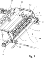
- the Fig. 7 is a detailed view of the device 1 for separating dough pieces according to the embodiment of the system 20 for producing dough pieces of the Fig. 6 .
- the shaft 6, which in the embodiment according to the Fig. 4 and Fig. 5 corresponds, extends over the entire width of the second conveyor device 2 and the third conveyor device 3.
- the axle stub 15 and the coupling 13 are accommodated in corresponding receptacles 31, 32 of a housing of the system 1, wherein the axle stub 15 is rotatably mounted in the first receptacle 31, while the coupling 13 is detachably connected to the drive 19 fastened to the housing.
- the longitudinal axis 8 of the shaft 6 lies at right angles to the conveying direction 4.
- the punching unit 25 has a punching plate 29 which can be moved in the vertical direction by means of actuators (not shown).
Landscapes
- Life Sciences & Earth Sciences (AREA)
- Engineering & Computer Science (AREA)
- Food Science & Technology (AREA)
- Manufacturing And Processing Devices For Dough (AREA)
Claims (13)
- Dispositif de séparation de pâtons (5.1, 5.2, 5.3), comportant un premier dispositif de transport (2) et un deuxième dispositif de transport (3) consécutif, sur lesquels des pâtons (5.1, 5.2, 5.3) posés sur ceux-ci peuvent être transportés dans une direction de transport (4), dans lequel le premier dispositif de transport (2) est entraîné à une première vitesse de transport et le deuxième dispositif de transport (3) est entraîné à une deuxième vitesse de transport, laquelle est supérieure à la première vitesse de transport, ainsi qu'un arbre (6) disposé à une première distance au-dessus de la région de transition entre le premier dispositif de transport (2) et le deuxième dispositif de transport (3), lequel peut être déplacé au moyen d'un entraînement (19) dans un mouvement de rotation autour d'un axe longitudinal (8) à une troisième vitesse, laquelle est supérieure à la première vitesse, et lequel s'étend sur toute la largeur des deux dispositifs de transport (2, 3) dans une direction transversale à la direction de transport (4), dans lequel au moins un élément entraîneur (9.1, 9.2) est disposé sur l'arbre (6) en faisant saillie radialement à partir de celui-ci, lequel est doté d'une surface de contact (10.1, 10.2) à une extrémité libre espacée d'une surface de l'arbre (6), caractérisé en ce que l'au moins un élément entraîneur (9.1, 9.2) est monté de façon à pouvoir être déplacé dans la direction radiale par rapport à l'arbre (6) et librement sur celui-ci, de telle façon que la surface de contact (10.1, 10.2) de l'au moins un élément entraîneur (9.1, 9.2) se déplace dans la direction radiale vers l'arbre (6) ou à distance de celui-ci du fait du mouvement de rotation de l'arbre (6) autour de l'axe longitudinal (8) en raison de la force de gravité et du poids propre de l'au moins un élément entraîneur (9.1, 9.2), dans lequel l'au moins un élément entraîneur (9.1, 9.2) présente une dimension telle que la surface de contact (10.1, 10.2) peut s'appliquer sur au moins un pâtons (5.1, 5.2, 5.3) posé sur le premier dispositif de transport (2), afin de pousser celui-ci à la troisième vitesse à partir du premier dispositif de transport (2) vers le deuxième dispositif de transport (3).
- Dispositif de séparation de pâtons (5.1, 5.2, 5.3) selon la revendication 1, caractérisé en ce que l'arbre (6) est doté d'un ou de plusieurs éléments entraîneurs (9.1, 9.2), lesquels sont disposés sur l'arbre (6) respectivement à une distance radiale de 360°/n les uns par rapport aux autres, n représentant le nombre des éléments entraîneur (9.1, 9.2) de l'arbre (6).
- Dispositif selon l'une des revendications 1 ou 2, caractérisé en ce que l'au moins un élément entraîneur (9.1, 9.2) est monté sur l'arbre (6) au moyen d'au moins un palier lisse.
- Dispositif selon les revendications 2 et 3, caractérisé en ce que l'arbre (6) présente un nombre pair d'éléments entraîneurs (9.1, 9.2), dans lequel des éléments entraîneurs (9.1, 9.2) disposés respectivement les uns par rapport aux autres à une distance radiale de 180° sur l'arbre (6) sont reliés entre eux par au moins deux barrettes de liaison (14.1, 14.2), lesquelles se situent dans la région des extrémités des éléments entraîneurs (9.1, 9.2) respectifs, dans lequel chacune des barrettes de liaison (14.1, 14.2) est reçue dans un guide coulissant de l'arbre (6).
- Dispositif selon l'une des revendications 1 à 4, caractérisé en ce que le dispositif (1) est doté d'une commande (28) commandant l'entraînement (19) de l'arbre (6) de telle façon que l'arbre (6) effectue un mouvement de rotation d'un angle de 360°/n autour de son axe longitudinal (7) à des intervalles de temps prédéfinis, n représentant le nombre des éléments entraîneurs (9.1, 9.2) disposés sur l'arbre (6).
- Dispositif selon la revendication 5, caractérisé en ce que le dispositif (1) est conçu de telle façon que la surface de contact (10.1, 10.2) de l'au moins un élément entraîneur (9.1, 9.2) vient s'appliquer à une position prédéfinie sur un pâtons (5.1, 5.2, 5.3) posé sur le premier dispositif de transport (2).
- Dispositif selon l'une des revendications 1 à 6, caractérisé en ce que le dispositif (1) est doté d'un moyen de réglage permettant de modifier la première distance.
- Dispositif selon l'une des revendications 1 à 7, caractérisé en ce que l'arbre (6) est relié à l'entraînement (19) par le biais d'une liaison amovible, en particulier par le biais d'un accouplement amovible (13).
- Dispositif selon l'une des revendications 1 à 8, caractérisé en ce qu'un élément de réglage (16.1, 16.2) est disposé sur l'arbre (6), avec lequel le déplacement de l'au moins un élément entraîneur (9.1, 9.2) dans la direction radiale à partir de la surface de l'arbre (6) peut être limité à au moins deux valeurs prédéterminées.
- Dispositif selon la revendication 9, caractérisé en ce que l'élément de réglage (16.1, 16.2) est disposé sur l'arbre (6) de façon à pouvoir être décalé linéairement dans la direction axiale et doté d'au moins deux surfaces de butée, lesquelles sont disposées à différentes distance de la surface de l'arbre (6) et avec lesquelles une région de butée (17) disposée sur l'au moins un élément entraîneur (9.1, 9.2), laquelle fait face à la surface de contact (10.1, 10.2), peut être amenée en butée.
- Procédé de séparation de pâtons (5.1, 5.2, 5.3) en particulier à l'aide d'un dispositif (1) selon l'une des revendications 1 à 10, comportant les étapes suivantes :a) transport d'au moins un pâton (5.1, 5.2, 5.3) sur un premier dispositif de transport (2) dans une direction de transport (4) à une première vitesse ;b) rotation, au moyen d'un entraînement (19) à une troisième vitesse supérieure à la première vitesse, d'un arbre (6) disposé à une première distance au-dessus d'une région de transition entre le premier dispositif de transport (2) et un deuxième dispositif de transport (3) consécutif à celui-ci dans la direction de transport (4), lequel est entraîné à une deuxième vitesse supérieure à la première vitesse dans la direction de transport (4), dans lequel au moins un élément entraîneur (9.1, 9.2) est disposé sur l'arbre (6) en faisant saillie radialement à partir de celui-ci, lequel est doté d'une surface de contact (10.1, 10.2) à une extrémité libre espacée d'une surface de l'arbre (6) et lequel est monté de façon à pouvoir être déplacé dans la direction radiale par rapport à l'arbre (6) et librement sur celui-ci ;c) saisie de l'au moins un pâtons (5.1, 5.2, 5.3) par l'au moins un élément entraîneur (9.1, 9.2) par application de la surface de contact (10.1, 10.2) de celui-ci sur l'au moins un pâtons (5.1, 5.2, 5.3) ;d) dans lequel l'au moins un pâtons (5.1, 5.2, 5.3) est entraîné par la surface de contact (10.1, 10.2) appliquée sur celui-ci avec l'au moins un élément entraîneur (9.1, 9.2) lors du mouvement de rotation de l'arbre (6), de telle façon qu'un pâtons (5.1, 5.2, 5.3) est poussé à partir du premier dispositif de transport (2) vers le deuxième dispositif de transport (3) à la troisième vitesse.
- Système de production de pâtons (5.1, 5.2, 5.3), comportant au moins une unité (25) destinée à estamper ou découper des pâtons (5.1, 5.2, 5.3) à partir d'une pâte ainsi qu'un dispositif (1) destiné à séparer des pâtons selon l'une des revendications 1 à 10, lequel est disposé en aval de l'unité (25) destinée à estamper ou découper des pâtons (5.1, 5.2, 5.3) à partir d'une pâte dans la direction de transport (4).
- Système selon la revendication 12, caractérisé en ce que l'unité (25) destinée à estamper ou découper des pâtons (5.1, 5.2, 5.3) à partir d'une pâte est configurée de telle façon que l'au moins une pâte est estampée ou découpée en des pâtons essentiellement triangulaires.
Priority Applications (3)
| Application Number | Priority Date | Filing Date | Title |
|---|---|---|---|
| EP23183391.4A EP4487687B1 (fr) | 2023-07-04 | 2023-07-04 | Dispositif et procédé de séparation de morceaux de pâte |
| PL23183391.4T PL4487687T3 (pl) | 2023-07-04 | 2023-07-04 | Urządzenie do separacji kęsów ciasta i sposób ich separacji |
| ES23183391T ES3031960T3 (en) | 2023-07-04 | 2023-07-04 | Device and method for separating pieces of dough |
Applications Claiming Priority (1)
| Application Number | Priority Date | Filing Date | Title |
|---|---|---|---|
| EP23183391.4A EP4487687B1 (fr) | 2023-07-04 | 2023-07-04 | Dispositif et procédé de séparation de morceaux de pâte |
Publications (3)
| Publication Number | Publication Date |
|---|---|
| EP4487687A1 EP4487687A1 (fr) | 2025-01-08 |
| EP4487687B1 true EP4487687B1 (fr) | 2025-04-30 |
| EP4487687C0 EP4487687C0 (fr) | 2025-04-30 |
Family
ID=87280328
Family Applications (1)
| Application Number | Title | Priority Date | Filing Date |
|---|---|---|---|
| EP23183391.4A Active EP4487687B1 (fr) | 2023-07-04 | 2023-07-04 | Dispositif et procédé de séparation de morceaux de pâte |
Country Status (3)
| Country | Link |
|---|---|
| EP (1) | EP4487687B1 (fr) |
| ES (1) | ES3031960T3 (fr) |
| PL (1) | PL4487687T3 (fr) |
Family Cites Families (8)
| Publication number | Priority date | Publication date | Assignee | Title |
|---|---|---|---|---|
| DE1155073B (de) * | 1962-11-15 | 1963-10-03 | Werner & Pfleiderer | Vorrichtung zum UEbertragen von Teigstuecken |
| DE1761695A1 (de) * | 1968-06-26 | 1971-08-05 | Hauni Werke Koerber & Co Kg | Zufuehrvorrichtung fuer Packmaschinen |
| JPS5115318B2 (fr) * | 1971-09-09 | 1976-05-15 | ||
| DE3708881C1 (de) | 1987-03-19 | 1988-10-13 | Haensel Otto Gmbh | Verfahren und Vorrichtung zum Ausrichten von Suesswarenstuecken |
| US5634549A (en) | 1995-04-14 | 1997-06-03 | Machine Builders And Design | Food item conveyor lane multiplier |
| CA2271175C (fr) * | 1999-05-05 | 2006-08-29 | Cae Electronics Ltd. Cae Electronique Ltee | Separateur de planches tournant a grande vitesse avec sabots escamotables et doigts a angle de pause variable |
| JP2000316463A (ja) | 1999-05-13 | 2000-11-21 | Shikishima Baking Co Ltd | 生地玉分離装置 |
| CN210960149U (zh) | 2019-03-26 | 2020-07-10 | 北京申晨机械设备有限公司 | 面片切割分离装置及面包生产设备 |
-
2023
- 2023-07-04 ES ES23183391T patent/ES3031960T3/es active Active
- 2023-07-04 EP EP23183391.4A patent/EP4487687B1/fr active Active
- 2023-07-04 PL PL23183391.4T patent/PL4487687T3/pl unknown
Also Published As
| Publication number | Publication date |
|---|---|
| ES3031960T3 (en) | 2025-07-14 |
| EP4487687C0 (fr) | 2025-04-30 |
| PL4487687T3 (pl) | 2025-08-18 |
| EP4487687A1 (fr) | 2025-01-08 |
Similar Documents
| Publication | Publication Date | Title |
|---|---|---|
| DE10084492B4 (de) | Vorrichtung und Verfahren zum Zuführen eines Nahrungsmittelteigs | |
| AT518494B1 (de) | Vorrichtung zum Schnitt von Teilbändern | |
| DE69001921T2 (de) | Verfahren und Vorrichtung zum Strecken von Teig. | |
| EP3009242B1 (fr) | Dispositif de coupe | |
| EP3718715B1 (fr) | Dispositif de coupe longitudinale pourvu de rouleau de convoyeur intégré | |
| EP3725706B1 (fr) | Système de transport variable et procédé d'utilisation d'un tel système de transport | |
| WO2013190125A1 (fr) | Trancheuse | |
| EP0226925B1 (fr) | Dispositif pour couper des portions | |
| DE69804709T2 (de) | Aufrollen eines Teigblattes | |
| EP2222156A1 (fr) | Découpe d'une masse de denrée alimentaire molle | |
| EP1010503B1 (fr) | Dispositif de coupe ayant un premier et un deuxième alignement d'outils pouvant se déplacer l'un vis-à-vis de l'autre le long de directions parallèles | |
| EP2510791B1 (fr) | Dispositif de formage d'une bande de pâte à partir de portions de pâtes alimentées | |
| EP4487687B1 (fr) | Dispositif et procédé de séparation de morceaux de pâte | |
| EP1285581A2 (fr) | Procédé et système pour former des produits pâteux roulés, notamment des croissants, à partir d'une pièce de pâte plane découpée | |
| EP4154716A1 (fr) | Dispositif de traitement de pâte et installation de traitement de pâte | |
| DE3812685C2 (de) | Verzögerungs-Vorrichtung für Bogenlagen | |
| DE3900414C2 (fr) | ||
| DE4413008A1 (de) | Faltvorrichtung für Blattlagen | |
| EP3417711B1 (fr) | Dispositif de preparation de pate | |
| EP0093847A2 (fr) | Appareil pour couper des pièces, en particulier des bonbons, d'une colonne de matière plastique | |
| DE69303766T2 (de) | Vorrichtung zum Verteilen von Brotteig oder dergleichen | |
| EP1258325A2 (fr) | Procédé ainsi que dispositif pour débiter en tranches de la charcuterie, du fromage ou des produits alimentaires similaires | |
| DE102022207528A1 (de) | Gegenzylinder-Anordnung | |
| EP1029640A2 (fr) | Dispositif pour opérer de façon transversale sur une couche de matériau, en particulier pour découper transversalement du papier | |
| DE102021134478A1 (de) | Teigverarbeitungsvorrichtung und Verfahren |
Legal Events
| Date | Code | Title | Description |
|---|---|---|---|
| PUAI | Public reference made under article 153(3) epc to a published international application that has entered the european phase |
Free format text: ORIGINAL CODE: 0009012 |
|
| STAA | Information on the status of an ep patent application or granted ep patent |
Free format text: STATUS: THE APPLICATION HAS BEEN PUBLISHED |
|
| AK | Designated contracting states |
Kind code of ref document: A1 Designated state(s): AL AT BE BG CH CY CZ DE DK EE ES FI FR GB GR HR HU IE IS IT LI LT LU LV MC ME MK MT NL NO PL PT RO RS SE SI SK SM TR |
|
| STAA | Information on the status of an ep patent application or granted ep patent |
Free format text: STATUS: REQUEST FOR EXAMINATION WAS MADE |
|
| GRAP | Despatch of communication of intention to grant a patent |
Free format text: ORIGINAL CODE: EPIDOSNIGR1 |
|
| STAA | Information on the status of an ep patent application or granted ep patent |
Free format text: STATUS: GRANT OF PATENT IS INTENDED |
|
| 17P | Request for examination filed |
Effective date: 20250122 |
|
| GRAS | Grant fee paid |
Free format text: ORIGINAL CODE: EPIDOSNIGR3 |
|
| INTG | Intention to grant announced |
Effective date: 20250218 |
|
| GRAA | (expected) grant |
Free format text: ORIGINAL CODE: 0009210 |
|
| STAA | Information on the status of an ep patent application or granted ep patent |
Free format text: STATUS: THE PATENT HAS BEEN GRANTED |
|
| AK | Designated contracting states |
Kind code of ref document: B1 Designated state(s): AL AT BE BG CH CY CZ DE DK EE ES FI FR GB GR HR HU IE IS IT LI LT LU LV MC ME MK MT NL NO PL PT RO RS SE SI SK SM TR |
|
| REG | Reference to a national code |
Ref country code: CH Ref legal event code: EP Ref country code: GB Ref legal event code: FG4D Free format text: NOT ENGLISH |
|
| REG | Reference to a national code |
Ref country code: DE Ref legal event code: R096 Ref document number: 502023000903 Country of ref document: DE |
|
| REG | Reference to a national code |
Ref country code: IE Ref legal event code: FG4D Free format text: LANGUAGE OF EP DOCUMENT: GERMAN |
|
| U01 | Request for unitary effect filed |
Effective date: 20250508 |
|
| U07 | Unitary effect registered |
Designated state(s): AT BE BG DE DK EE FI FR IT LT LU LV MT NL PT RO SE SI Effective date: 20250515 |
|
| REG | Reference to a national code |
Ref country code: ES Ref legal event code: FG2A Ref document number: 3031960 Country of ref document: ES Kind code of ref document: T3 Effective date: 20250714 |
|
| U20 | Renewal fee for the european patent with unitary effect paid |
Year of fee payment: 3 Effective date: 20250728 |
|
| PGFP | Annual fee paid to national office [announced via postgrant information from national office to epo] |
Ref country code: ES Payment date: 20250828 Year of fee payment: 3 |
|
| PG25 | Lapsed in a contracting state [announced via postgrant information from national office to epo] |
Ref country code: NO Free format text: LAPSE BECAUSE OF FAILURE TO SUBMIT A TRANSLATION OF THE DESCRIPTION OR TO PAY THE FEE WITHIN THE PRESCRIBED TIME-LIMIT Effective date: 20250730 Ref country code: GR Free format text: LAPSE BECAUSE OF FAILURE TO SUBMIT A TRANSLATION OF THE DESCRIPTION OR TO PAY THE FEE WITHIN THE PRESCRIBED TIME-LIMIT Effective date: 20250731 |
|
| PGFP | Annual fee paid to national office [announced via postgrant information from national office to epo] |
Ref country code: TR Payment date: 20250721 Year of fee payment: 3 Ref country code: PL Payment date: 20250618 Year of fee payment: 3 |
|
| PG25 | Lapsed in a contracting state [announced via postgrant information from national office to epo] |
Ref country code: HR Free format text: LAPSE BECAUSE OF FAILURE TO SUBMIT A TRANSLATION OF THE DESCRIPTION OR TO PAY THE FEE WITHIN THE PRESCRIBED TIME-LIMIT Effective date: 20250430 |
|
| PG25 | Lapsed in a contracting state [announced via postgrant information from national office to epo] |
Ref country code: RS Free format text: LAPSE BECAUSE OF FAILURE TO SUBMIT A TRANSLATION OF THE DESCRIPTION OR TO PAY THE FEE WITHIN THE PRESCRIBED TIME-LIMIT Effective date: 20250731 |
|
| PG25 | Lapsed in a contracting state [announced via postgrant information from national office to epo] |
Ref country code: IS Free format text: LAPSE BECAUSE OF FAILURE TO SUBMIT A TRANSLATION OF THE DESCRIPTION OR TO PAY THE FEE WITHIN THE PRESCRIBED TIME-LIMIT Effective date: 20250830 |
|
| PG25 | Lapsed in a contracting state [announced via postgrant information from national office to epo] |
Ref country code: SM Free format text: LAPSE BECAUSE OF FAILURE TO SUBMIT A TRANSLATION OF THE DESCRIPTION OR TO PAY THE FEE WITHIN THE PRESCRIBED TIME-LIMIT Effective date: 20250430 |
|
| PG25 | Lapsed in a contracting state [announced via postgrant information from national office to epo] |
Ref country code: CZ Free format text: LAPSE BECAUSE OF FAILURE TO SUBMIT A TRANSLATION OF THE DESCRIPTION OR TO PAY THE FEE WITHIN THE PRESCRIBED TIME-LIMIT Effective date: 20250430 |
|
| PG25 | Lapsed in a contracting state [announced via postgrant information from national office to epo] |
Ref country code: SK Free format text: LAPSE BECAUSE OF FAILURE TO SUBMIT A TRANSLATION OF THE DESCRIPTION OR TO PAY THE FEE WITHIN THE PRESCRIBED TIME-LIMIT Effective date: 20250430 |
|
| PLBE | No opposition filed within time limit |
Free format text: ORIGINAL CODE: 0009261 |
|
| STAA | Information on the status of an ep patent application or granted ep patent |
Free format text: STATUS: NO OPPOSITION FILED WITHIN TIME LIMIT |
|
| REG | Reference to a national code |
Ref country code: CH Ref legal event code: L10 Free format text: ST27 STATUS EVENT CODE: U-0-0-L10-L00 (AS PROVIDED BY THE NATIONAL OFFICE) Effective date: 20260311 |
|
| 26N | No opposition filed |
Effective date: 20260202 |