EP4487706A1 - Procédé de chauffage de milieu, module d'évaporation, cartouche et équipement pour inspiration - Google Patents
Procédé de chauffage de milieu, module d'évaporation, cartouche et équipement pour inspiration Download PDFInfo
- Publication number
- EP4487706A1 EP4487706A1 EP23763050.4A EP23763050A EP4487706A1 EP 4487706 A1 EP4487706 A1 EP 4487706A1 EP 23763050 A EP23763050 A EP 23763050A EP 4487706 A1 EP4487706 A1 EP 4487706A1
- Authority
- EP
- European Patent Office
- Prior art keywords
- cartridge
- active substance
- medium
- air
- particles
- Prior art date
- Legal status (The legal status is an assumption and is not a legal conclusion. Google has not performed a legal analysis and makes no representation as to the accuracy of the status listed.)
- Pending
Links
Images





Classifications
-
- A—HUMAN NECESSITIES
- A24—TOBACCO; CIGARS; CIGARETTES; SIMULATED SMOKING DEVICES; SMOKERS' REQUISITES
- A24D—CIGARS; CIGARETTES; TOBACCO SMOKE FILTERS; MOUTHPIECES OF CIGARS OR CIGARETTES; MANUFACTURE OF TOBACCO SMOKE FILTERS OR MOUTHPIECES
- A24D1/00—Cigars; Cigarettes
- A24D1/14—Tobacco cartridges for pipes
-
- A—HUMAN NECESSITIES
- A24—TOBACCO; CIGARS; CIGARETTES; SIMULATED SMOKING DEVICES; SMOKERS' REQUISITES
- A24F—SMOKERS' REQUISITES; MATCH BOXES; SIMULATED SMOKING DEVICES
- A24F1/00—Tobacco pipes
- A24F1/30—Hookahs
-
- A—HUMAN NECESSITIES
- A24—TOBACCO; CIGARS; CIGARETTES; SIMULATED SMOKING DEVICES; SMOKERS' REQUISITES
- A24F—SMOKERS' REQUISITES; MATCH BOXES; SIMULATED SMOKING DEVICES
- A24F40/00—Electrically operated smoking devices; Component parts thereof; Manufacture thereof; Maintenance or testing thereof; Charging means specially adapted therefor
- A24F40/40—Constructional details, e.g. connection of cartridges and battery parts
- A24F40/42—Cartridges or containers for inhalable precursors
-
- A—HUMAN NECESSITIES
- A24—TOBACCO; CIGARS; CIGARETTES; SIMULATED SMOKING DEVICES; SMOKERS' REQUISITES
- A24F—SMOKERS' REQUISITES; MATCH BOXES; SIMULATED SMOKING DEVICES
- A24F40/00—Electrically operated smoking devices; Component parts thereof; Manufacture thereof; Maintenance or testing thereof; Charging means specially adapted therefor
- A24F40/40—Constructional details, e.g. connection of cartridges and battery parts
- A24F40/46—Shape or structure of electric heating means
-
- A—HUMAN NECESSITIES
- A24—TOBACCO; CIGARS; CIGARETTES; SIMULATED SMOKING DEVICES; SMOKERS' REQUISITES
- A24F—SMOKERS' REQUISITES; MATCH BOXES; SIMULATED SMOKING DEVICES
- A24F40/00—Electrically operated smoking devices; Component parts thereof; Manufacture thereof; Maintenance or testing thereof; Charging means specially adapted therefor
- A24F40/40—Constructional details, e.g. connection of cartridges and battery parts
- A24F40/48—Fluid transfer means, e.g. pumps
- A24F40/485—Valves; Apertures
-
- A—HUMAN NECESSITIES
- A24—TOBACCO; CIGARS; CIGARETTES; SIMULATED SMOKING DEVICES; SMOKERS' REQUISITES
- A24F—SMOKERS' REQUISITES; MATCH BOXES; SIMULATED SMOKING DEVICES
- A24F40/00—Electrically operated smoking devices; Component parts thereof; Manufacture thereof; Maintenance or testing thereof; Charging means specially adapted therefor
- A24F40/50—Control or monitoring
-
- A—HUMAN NECESSITIES
- A24—TOBACCO; CIGARS; CIGARETTES; SIMULATED SMOKING DEVICES; SMOKERS' REQUISITES
- A24F—SMOKERS' REQUISITES; MATCH BOXES; SIMULATED SMOKING DEVICES
- A24F40/00—Electrically operated smoking devices; Component parts thereof; Manufacture thereof; Maintenance or testing thereof; Charging means specially adapted therefor
- A24F40/30—Devices using two or more structurally separated inhalable precursors, e.g. using two liquid precursors in two cartridges
Definitions
- the invention relates to the service sector and can be used in the creation of appliances for the inhalation of a mixture of air, vapour and particles of an active substance, which comprise a liquid-containing vessel, for example smoking appliances, preferably hookahs.
- Smoking appliances which firstly appeared in the countries of the East, known as hookahs, became extremely popular in recent years, and they are an alternative to ordinary cigarettes, particularly, among young adults.
- Smoking appliances comprise a vessel partially filled with water or any other liquid medium. Suction through a tip creates a low air pressure in a vessel.
- a smoke tube goes to the water level, its head part is located near an upper end, where tobacco is placed, which is heated by coal from an upper side. A mixture of air, vapour and smoke particles appears as a result of tobacco heating, then this mixture is inhaled by the smoker. It is obvious that the heat produced by combusting coal may lead to carbon monoxide poisoning, burns or, in extreme cases, even a fire.
- hookahs As hookahs are filled manually, high-quality preparation of hookahs for the use is also not guaranteed. For this reason, hookahs, which are more common today, should only be used outdoors or in rooms with a guaranteed supply of fresh air.
- hookahs according to the state of the art are very heavy and bulky, hookahs shall be made up of several parts, and their individual parts are inconvenient to transport. They are also difficult to clean and often do not meet hygiene standards.
- E-hookahs are known from patent documents US4133318 published on 01/03/1979 , US010820626 published on 02/11/2020 or from the application for invention US 2012/0199572 published on 09/08/2012 , some of the above-mentioned problems can be reduced when using them, but the result is still not satisfactory enough.
- the patented appliance for inhalation of a mixture of air, vapour and particles of an active substance is a compact device with a reservoir-like vessel to be filled with water or any other liquid, such appliance has at least one suction device, through which the user inhales a mixture of air, vapour and, in this particular case, smoke particles.
- a heating camera for a medium that releases smoke for example, tobacco, located on the opposite end of the body of a vessel and containing an air inlet.
- the heating camera comprises a slot for a capsule for a medium that releases smoke.
- a smoking unit of a smoking device is characterized by the fact that a slot for a capsule for a medium that releases smoke is designed for tight contact with the walls of a capsule, heating elements are also in direct contact with the walls of a capsule. Heating a medium that releases smoke occurs only through the specified walls.
- the disadvantages of such technical solution are difficulty of maintaining a constant temperature of a medium, high probability of overheating a medium, and probability of a medium combustion with release of undesirable substances, as well as consumption of high power.
- a cartridge for a medium that releases particles of an active substance described in US 10,820,626
- a cartridge is made with exterior walls, a cover and a bottom with a first opening in the center.
- a first opening is made in the form of a hollow protrusion, consisting of side walls extending upward to the top of the body for contact with a cartridge slot, and having a plurality of second openings for passage of heated air. Said openings are made in the walls of said hollow protrusion and in a cover.
- the aim of this invention is to broaden the range of appliances for the inhalation of a mixture of air, vapour and particles of an active substance with a liquid-containing vessel by developing a novel, effective and safe method of heating a medium that releases an active substance, ensuring the production of a mixture of air, vapour and particles of an active substance without combustion, a vaporation module and a cartridge implementing this method and a device for inhalation of said mixture using such a module.
- the aim set in the method of heating a medium that releases particles of an active substance for an appliance for inhalation of a mixture of air, vapour and particles of an active substance using a cartridge containing said medium characterized in that the air entering an appliance for inhalation is heated to a temperature of up to 400°C, then heated air is passed around a cartridge and through said medium.
- a vaporation module for an appliance for inhalation of a mixture of air, vapour and particles of an active substance through an inhalation hose with a liquid-containing vessel contains a heating unit, a cartridge for a medium that releases particles of an active substance, and a slot adapted for a cartridge for a medium that releases particles of an active substance, and also contains a tube between said slot for a cartridge and said vessel
- a cartridge is made with a bottom, with a hollow protrusion in the center with the formation of a first opening for connection with said tube, and with a plurality of second openings for passage of heated air
- a cartridge is provided with an unbroken cover
- said slot for a cartridge has a wall surrounding a cartridge from the side and from below and forming a gap with a wall and a bottom of a cartridge for passage of heated air; and a total cross-sectional area of said gap is not less than cross-sectional area of an inhalation hose.
- a module may be provided with a lower heating element placed under a cartridge slot parallel to its bottom.
- Upper and lower heating elements are preferably adjustable.
- a cartridge for a medium that releases particles of an active substance made with exterior walls, a cover and a bottom with a hollow protrusion formed in the center, consisting of side walls extending upward to the top of the body for contact with a slot for a cartridge, and a plurality of second openings for the passage of heated air, has been solved in that second openings are made in said exterior walls of a cartridge and in said side walls of said body; second openings are made closed at the top, and said cover and bottom of a cartridge are made unbroken.
- said second openings in the upper third of side walls of said body have a total cross-sectional area from 50 to 201 mm 2
- said second openings in central part of said exterior walls of a cartridge have a total cross-sectional area from 50 to 201 mm 2 .
- Said controller has been preferably developed to provide controlled power to a heating unit.
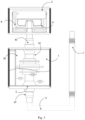
- An appliance for inhalation of a mixture of air, vapour and particles of an active substance (hereinafter referred to as the aerosol) in this particular example is represented in the form of a hookah or a smoking pipe ( fig. 1 , 2 , 3 ), and said appliance comprises a liquid-containing a vessel 1, a vaporating module 2, an electronic module, including a power adapter 3 and a programmed controller 4.
- a vessel 1 comprises an opening 5 for an aerosol-inhaling hose 6 (in this particular example - smoke); a hose 6 is equipped with a tip 7.
- a vaporation module 2 ( fig. 1 ) comprises a heating unit, a slot 8, and a tube 10 between said slot 8 for a cartridge 9 and said vessel 1.
- a slot 8 is adapted for a cartridge 9 for a medium that releases particles of an active substance (for example, tobacco mixtures that release smoke).
- a cartridge 9 for a medium 11 that releases particles of an active substance (one of the embodiment examples ( fig.16 )) is made with a bottom 12 with a hollow protrusion 13 formed in the center with the formation of a first opening 14 for connection with said tube 10 and a plurality of second openings 15 for passage of heated air; and a cartridge is provided with an unbroken cover 16.
- a slot 8 ( fig. 15 ) for the described embodiment example of a cartridge 9 has a wall 17 surrounding a cartridge 9 from the side and from below and forming a gap with exterior wall 18, and bottom 12 of a cartridge 9 for passage of heated air, and total cross-sectional area of said gap is not less than cross-sectional area of an inhalation hose 6.
- a heating unit ( fig.2 , 3 ) contains an upper heating element 19 ( fig.5, 6 ), an upper heating element 19 has the possibility of through passage and heating of external air and placed above a cartridge 9 cover 16 with a gap.
- a heating unit comprises a lower heating element 20 placed under a slot 8 for a cartridge 9 parallel to the bottom.
- Upper 19 and lower 20 heating elements are made adjustable. Control of heating, cooling, and other ongoing processes (charging and discharging batteries, networks and communication protocols with external devices, switching the device on and off) is performed according to a specified algorithm using a programmable controller 4.
- Heating elements, as well as other electronics, are powered by a power supply unit 3, which is a Li-Ion battery 121 ( Fig. 2 ) and/or an external power supply (not shown in the drawings).
- a power supply unit 3 which is a Li-Ion battery 121 ( Fig. 2 ) and/or an external power supply (not shown in the drawings).
- the appliance status is shown on display 22, which can be integrated into an exterior shell of claimed device ( fig. 1 ).
- the user can issue commands using touch buttons 23 on a front panel, via an application on a mobile device (not shown in the drawings) or some other method of human-machine interaction. Connection with the mobile device is carried out via Bluetooth or based on some other wireless connection.
- an upper heating element 19 ( fig.8 ) is heating of air passing through it up to the stated temperature.
- an upper heating element 19 was provided in a complex form, for example, in the form of a stack of ceramic plates. Cold air is sucked in through at least one opening 24 in an upper ceramic plate 25 (in this example, fig.8 demonstrates two openings 24, in reality, there are several openings, and they are placed circle-wise), and then cold air passes tunnel 26 formed by plates 25 and 27. Since a middle ceramic plate 27 is in a close proximity to a thermoelectric element 28, air mass is preheated. The bend on a lower ceramic plate 29 allows to increase a preheating area by increasing the length of air path.
- thermoelectric element 28 is placed in a camera 30 formed by plates 27 and 29, air temperature increases from 10°C to 400°C when passing through it, then heated air passes through channel 31 and enters a slot 8, located directly under an upper heating element 19. No gap is formed between these elements due to the precise adjustment of a plane of plate 28 and a slot 8, which eliminates the ingress of air bypassing this system.
- a tube 10 between said slot 8 for a cartridge 9 and said vessel 1 may be a system of tubes made of aluminum, copper, stainless steel, glass, ceramics, various types of plastics or any other material with a diameter from 10 to 60 mm, or may be made as part of a multi-segment tube 32 ( Fig. 10-12 ) made of aluminum, copper, stainless steel, glass, ceramics, various types of plastics or any other material with a diameter from 10 to 60 mm.
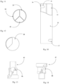
- a multi-segment tube 32 an extrusion method of production with subsequent processing is used. In this example, a cross-section of a tube 32 is divided into three sectors ( Fig. 11 ).
- Sector 33 performs the functions of a previously indicated tube 10 and is a channel for transferring the aerosol from a slot 8 or a cartridge 9 to a vessel 1; sector 34 performs the functions of a previously indicated section of hose 6 and is a channel for transferring the aerosol from a vessel 1 to a hose 6 to a tip 7.
- Sector 35 is a cable channel for laying power and signal cables from a power supply unit 3 and a programmable controller 4 to an upper heating element 19. The shape and arrangement of sectors may be different, depending on the design features of this particular device for inhaling the aerosol.
- a vessel 1 is designed for liquid, which serves as the cooling liquid filter for filtration and cooling of the aerosol.
- the volume of liquid depends on shape and size of a vessel 1 and ranges from 10% to 80% of its total volume. In this case, an upper "water-free" volume 39 is formed in a vessel 1.
- a vessel 1 is equipped with a forced cooling unit 40 (see Fig. 2 ). Forced cooling of liquid allows for enhancing the filtering effect, improving the taste of the aerosol, and reducing the volume of the required filtering liquid.
- a forced cooling unit consists of a liquid cooling radiator 41, a thermoelectric element 42 based on the Peltier effect, an additional heat dissipation radiator 43, and a hot air removal fan 44.
- a liquid cooling radiator 41 can completely occupy the bottom of a vessel 1 or be only a part of it.
- a forced cooling unit is controlled using a programmable controller 4.
- the user can, at will, turn on or off a forced liquid cooling using touch buttons 23 on the front panel of an inhalation appliance or in a special application launched on the user's third-party device (not shown in the drawings). Forced cooling can be turned on/off during the inhalation process, and it can also be turned on in advance from sleep mode, manually or automatically (using a timer) in said special application.
- an upper part 45 of a transition section is provided (see Fig. 3 ) in order to match a sector-shaped cross-section of sector 33 of a tube 32 with radial section of a slot 8 and an opening 14 in a cartridge 9.
- An upper part 45 may include a first check valve 46 ( Fig. 13 ).
- This valve may be made according to the principle of a ball check valve, a mushroom check valve, a cone check valve, a membrane check valve, or it may have another design that allows to implement the function of preventing water from penetrating from a vessel 1 to lower 20 and upper 19 heating elements, for example, when the device is overturned or when excess pressure is created in "water-free" volume 39 of a vessel 1, as excess pressure is capable of displacing liquid from a vessel 1 through a tube 10 to heating elements.
- a lower part 47 of a transition section is provided (see Fig. 3 ) in order to match a radial section of a hose 6 with a sector-shaped cross-section of sector 34 of a tube 32.
- a lower part 47 may also include a second check valve 48 ( Fig. 14 ).
- This valve may also be made according to the principle of a ball check valve, a mushroom check valve, a cone check valve, a membrane check valve, or it may have another design that allows to implement the function of preventing the creation of excess pressure in "water-free" volume 39 of a vessel 1, as excess pressure is capable of displacing liquid from a vessel 1 through a tube 10 to heating elements, this design is one of the stages of protecting heating elements from liquid getting on them. Also, thanks to this valve, the probability of viruses and bacteria getting from the user into a vessel 1 may be reduced.
- a programmable controller 4 All processes occurring in claimed appliance for inhaling the aerosol are regulated by a programmable controller 4. Its aim includes monitoring and controlling the temperature of heating elements 19 and 20, liquid temperature, charging and discharging batteries 21, networks and communication protocols with external devices, switching on and off the device for inhaling the aerosol.
- the appliance status is displayed on display 22, which in this example is integrated into a wall of a body of an inhalation appliance ( Fig. 1 ).
- the user can issue commands using touch buttons 23 on the front panel of an inhalation appliance or via a special application launched on a third-party device of the user (not shown in the drawings) or some other method of human-machine interaction. Connection with the user's device is carried out via Bluetooth or based on some other wireless connection.
- a cartridge 9 for a medium 11 that releases particles of an active substance ( Fig. 6, 7 ) is made with exterior walls 18, an unbroken bottom 12 with a hollow protrusion 13 formed in the center and closed at the top with the formation of a first opening 14 in the center for connection with said tube 10 and a plurality of second openings 15 for the passage of heated air, and a cartridge 9 is provided with unbroken cover 16.
- a hollow protrusion 13 closed at the top consists of side walls 49 extending upward to the top of a protrusion 13.
- Second openings 15 are made in the said outer walls 18 of cartridge 9 and in said side walls 49 of said protrusion 13.
- second openings 15, made in the upper third of said side walls 49 of said protrusion 13, have a total cross-sectional area of 50 to 201 mm 2
- said second openings, made in the central part of said exterior walls 18 of cartridge 9, have a total cross-sectional area of 50 to 201 mm 2 .
- the claimed appliance for inhalation of the aerosol is used as follows.
- the claimed appliance for inhalation of the aerosol is a fully automated device powered by built-in battery 21. Average operation time is 1.5 hour.
- a vessel 1 Before the use, a vessel 1 is filled with water or any other liquid harmless for people.
- the user places a specialized cartridge 9 into a slot 8 and presses any sensor button 23 on the front panel of an appliance for aerosol inhalation.
- the onboard electronics is launched.
- the command takes a vaporation module 2 out of sleep mode and starts heating the heating elements 19, 20 according to the specified algorithm.
- a medium that releases particles of an active substance is heated to the temperature specified by the program, a display 22 on the front panel shows the heating icon, the current temperature and the specified power expressed as percentage.
- the power of a heater 20 is automatically reduced to almost zero, and the power of a heater 19 - to the value specified in the settings. From this moment on, the user can use an appliance for inhalation of the aerosol.
- Information about the loaded presets will be shown on display 22 and in the application running on the user's third-party device. To remove the presets, simply decrease or increase the temperature using touch buttons 23 on the front panel of an aerosol inhalation appliance or in the application running on the user's third-party device. This will return the original settings.
- thermoelectric element 28 In a camera 30 formed by plates 25 and 29, a thermoelectric element 28 is placed, when passing through it, the air temperature increases from 10°C to 400°C, then the heated air passes through channel 31 and enters slot 8, located directly under an upper heating element 19. Due to the precise adjustment of a plane of plate 29 and a slot 8, no gap is formed between these elements; this eliminates the ingress of air bypassing this system.
- a cartridge 9 for a medium 11 that releases particles of an active substance (in one of the embodiments ( Fig. 16 )) is made with a bottom 12 with a hollow protrusion 13 formed in the center with the formation of a first opening 14 for connection with said tube 10 and a plurality of second openings 15 for the passage of heated air.
- a cartridge 9 is provided with an unbroken cover 16.
- a slot 8 for a cartridge has a wall 17 surrounding a cartridge 9 from the side and from below and forming a gap with the wall and the bottom of a cartridge 9.
- an upper heating element 19 fits tightly to ends of walls of a slot 8, but does not touch an unbroken cover 16 of a cartridge due to a gap, the heated air with a temperature of up to 400°C practically does not affect a medium 11 in a cartridge 9 from above, and through the said gap between the walls of slot 8 and cartridge 9.
- the heated air passes along outer walls 18 of a cartridge 9 to its bottom 12, uniformly heating a medium 11 in a cartridge 9 from the side, and then heated air enters a gap between bottom of a slot 8 and bottom 12 of a cartridge 9.
- bottom 12 of a cartridge 9 is made with a plurality of second openings 15, the heated air seeps into a cartridge 9, through the entire volume of a medium 11 that releases particles of an active substance; the heated air uniformly increases the temperature in the entire volume of a medium 11 without burning it. Then the heated air accumulates under cover 16 of a cartridge 9 capturing said particles of an active substance, from where the air is sucked into a tube 10 and, then, as described above, through a liquid filter, a hose 6 and a tip 7 gets to the user.
- the claimed design of a vaporation module embodies an effective and safe method of heating a medium that releases an active substance, ensuring the production of a mixture of air, vapour and particles of an active substance without combustion.
- the total cross-sectional area of a gap between walls and bottom of a slot 8 and walls and bottom of a cartridge 9 is not less than the cross-sectional area of an inhalation hose 6, which ensures easy and unimpeded inhalation of the aerosol formed by air, vapour and particles of an active substance.
- a cartridge 9 and a slot 8 also form a gap, through which the heated air (not shown in fig.7 ) passes from a heating element to second openings 15 in external walls 18 of a cartridge 9.
- air flows 50 pass through a medium 11 that releases particles of an active substance (for example, a tobacco or non-tobacco mixture), heating a medium and releasing the aerosol.
- the aerosol together with air flows 50, moves to second openings 15 in side wall 49 of a protrusion 13, getting inside a protrusion 13. Since a protrusion 13 is closed from above, the aerosol can then only pass into an opening 11, from where it is sucked into a tube 10 and, then, as described above, it gets to the user through a liquid filter, a hose 6 and a tip 7.
- a medium 11 Due to such arrangement of second openings 15 and given path of air flows 50, maximum temperature is achieved in zone 51 of a medium 11 that releases the particles of an active substance, and maximum temperature weakens away from main air flow (see Fig. 7 ), thereby allowing not to dry the entire volume of a medium 11 that releases particles of an active substance.
- a medium 11 has a lower temperature than in zone 51.
- the aerosol is released in zone 51, in zone 52 the aerosol is released as a medium 11 warms up. This improvement allows more rational use of a medium 11 that releases particles of an active substance, reduces the initial aromatic shock, increases the quality time of use of a medium, and reduces the amount of released harmful impurities per time unit.
- Elimination of second openings in a bottom 12 of a cartridge 9 made it possible to reduce the ingress of liquid component of a medium 11 onto surface of a slot 8 many times over, which in turn reduces the need to clean a slot 8. Absence of second openings in a cover 16 of a cartridge 9 reduces the possibility of vaporation from a medium 11 getting onto an upper heating element 19 (not shown in Fig. 7 ).
- Thermoelectric element 28 is controlled using commands from a programmable controller 4.
- a controller 4 regulates all processes occurring in heating elements 19 and 20. If an emergency occurs, for example, an inhalation appliance overturns, a command is sent to heating elements 19 and 20 to disconnect them from a power supply unit 3. Together with the system of valves described above, this allows for making the safest possible device for inhaling aerosol.
- an air exhaustion sensor (not shown in the drawing) may be installed, due to which it may be possible to quickly increase the power on a thermoelectric element 28. Due to sharp increase in the temperature of the air passing through camera 30, it becomes possible to act with a thermal shock on the environment in a cartridge 9.
- thermoelectric element 28 Without receiving a signal from an exhaustion sensor, a thermoelectric element 28 switches to a temperature balance maintenance mode. This reduces the energy costs of a device and, as a result, increases battery life of a device. It also helps to reduce the consumption of a medium that releases particles of an active substance, since there is no burning of it, and to improve taste of the aerosol. Maximum temperature of a thermoelectric element 24 is selected for the types of specified medium for better disclosure of taste and reduction of harmful substances in the formed aerosol.
- a novel original vaporation unit has been developed, implementing a novel, effective and safe method of heating a medium that releases an active substance.
- Such unit ensures the production of a mixture of air, steam and particles of an active substance without combustion, as well as a novel effective and safe device for inhalation of a mixture of air, vapour and particles of an active substance without combustion using said vaporation unit.
Landscapes
- Catching Or Destruction (AREA)
- Manufacture Of Tobacco Products (AREA)
- Cigarettes, Filters, And Manufacturing Of Filters (AREA)
- Agricultural Chemicals And Associated Chemicals (AREA)
Applications Claiming Priority (2)
| Application Number | Priority Date | Filing Date | Title |
|---|---|---|---|
| EA202200027 | 2022-03-03 | ||
| PCT/IB2023/020020 WO2023166354A1 (fr) | 2022-03-03 | 2023-02-28 | Procédé de chauffage de milieu, module d'évaporation, cartouche et équipement pour inspiration |
Publications (2)
| Publication Number | Publication Date |
|---|---|
| EP4487706A1 true EP4487706A1 (fr) | 2025-01-08 |
| EP4487706A8 EP4487706A8 (fr) | 2025-07-30 |
Family
ID=87883145
Family Applications (1)
| Application Number | Title | Priority Date | Filing Date |
|---|---|---|---|
| EP23763050.4A Pending EP4487706A1 (fr) | 2022-03-03 | 2023-02-28 | Procédé de chauffage de milieu, module d'évaporation, cartouche et équipement pour inspiration |
Country Status (9)
| Country | Link |
|---|---|
| US (1) | US20250194666A1 (fr) |
| EP (1) | EP4487706A1 (fr) |
| JP (1) | JP2025508976A (fr) |
| KR (1) | KR20240157052A (fr) |
| CN (1) | CN118804695A (fr) |
| AU (1) | AU2023226866A1 (fr) |
| CA (1) | CA3245307A1 (fr) |
| IL (1) | IL315277A (fr) |
| WO (1) | WO2023166354A1 (fr) |
Families Citing this family (1)
| Publication number | Priority date | Publication date | Assignee | Title |
|---|---|---|---|---|
| GB2620122A (en) * | 2022-06-27 | 2024-01-03 | Air Ip Holdings Ltd | Capsule |
Family Cites Families (6)
| Publication number | Priority date | Publication date | Assignee | Title |
|---|---|---|---|---|
| US4133318A (en) | 1977-06-20 | 1979-01-09 | Ronald Gross | Water pipe |
| US9149586B2 (en) | 2011-02-07 | 2015-10-06 | Seibo Ping-Cheng SHEN | Herbal vaporization apparatus and method |
| TWI608805B (zh) * | 2012-12-28 | 2017-12-21 | 菲利浦莫里斯製品股份有限公司 | 加熱型氣溶膠產生裝置及用於產生具有一致性質的氣溶膠之方法 |
| CN112772973B (zh) | 2014-05-12 | 2025-01-21 | 空气Ip控股有限公司 | 一种可燃材料的器皿 |
| DE102015121435B4 (de) * | 2015-11-10 | 2020-06-18 | AF Development Holding Ltd. | Wasserpfeife |
| KR20220121796A (ko) * | 2019-12-30 | 2022-09-01 | 필립모리스 프로덕츠 에스.에이. | 공기 예열로 에어로졸 형성 기재를 가열하기 위한 장치 |
-
2023
- 2023-02-28 CA CA3245307A patent/CA3245307A1/fr active Pending
- 2023-02-28 KR KR1020247032185A patent/KR20240157052A/ko active Pending
- 2023-02-28 WO PCT/IB2023/020020 patent/WO2023166354A1/fr not_active Ceased
- 2023-02-28 IL IL315277A patent/IL315277A/en unknown
- 2023-02-28 AU AU2023226866A patent/AU2023226866A1/en active Pending
- 2023-02-28 EP EP23763050.4A patent/EP4487706A1/fr active Pending
- 2023-02-28 JP JP2024552329A patent/JP2025508976A/ja active Pending
- 2023-02-28 US US18/843,001 patent/US20250194666A1/en active Pending
- 2023-02-28 CN CN202380024883.7A patent/CN118804695A/zh active Pending
Also Published As
| Publication number | Publication date |
|---|---|
| CN118804695A (zh) | 2024-10-18 |
| KR20240157052A (ko) | 2024-10-31 |
| EP4487706A8 (fr) | 2025-07-30 |
| AU2023226866A1 (en) | 2024-10-17 |
| US20250194666A1 (en) | 2025-06-19 |
| JP2025508976A (ja) | 2025-04-10 |
| IL315277A (en) | 2024-10-01 |
| WO2023166354A1 (fr) | 2023-09-07 |
| CA3245307A1 (fr) | 2025-06-13 |
Similar Documents
| Publication | Publication Date | Title |
|---|---|---|
| JP7639061B2 (ja) | 香味制御を提供するエアロゾル送達装置 | |
| JP6737849B2 (ja) | たばこ用電子装置 | |
| JP6758437B2 (ja) | 電子蒸気吸入器 | |
| CN109661182B (zh) | 非燃烧型香味吸取器 | |
| KR102513244B1 (ko) | 말단 히터를 구비한 전기 가열식 에어로졸 발생 시스템 | |
| US9532603B2 (en) | Aerosol generating device and system with improved airflow | |
| US20170027223A1 (en) | Vaporizer With Multiple-Chamber Heating | |
| JP2017533726A (ja) | 電子ニコチン送達システムで使用するためのディスポーザブルカートリッジ | |
| CN109068748A (zh) | 用于加热可抽吸材料的设备 | |
| BRPI0616628A2 (pt) | sistema elétrico de exalar fumos | |
| EA013849B1 (ru) | Устройство для испарения испаряемого вещества | |
| CN114521687A (zh) | 具有空气入口的装置 | |
| US12207685B2 (en) | Vaporizing article and containers for vaporizing articles | |
| CN203748671U (zh) | 电子吸烟装置 | |
| KR101315296B1 (ko) | 전자담배 | |
| JP7614208B2 (ja) | 空気予熱を有するエアロゾル形成基体を加熱するための装置 | |
| EP4487706A1 (fr) | Procédé de chauffage de milieu, module d'évaporation, cartouche et équipement pour inspiration | |
| CN104013110A (zh) | 烘焙型雾化器及具有该雾化器的电子烟 | |
| CN209073556U (zh) | 一种具有非接触式热元件的烟草加热装置 | |
| CN207040886U (zh) | 易于调节烟气的双腔电子烟 | |
| CN110419787A (zh) | 一种低温烟具 | |
| EA047702B1 (ru) | Способ нагревания среды, выделяющей активное вещество, испарительный модуль и приспособление для вдыхания | |
| CN203873015U (zh) | 烘焙型雾化器及具有该雾化器的电子烟 | |
| CN116138505B (zh) | 一种可抽吸材料加热装置及其加热方法 | |
| EA053002B1 (ru) | Испарительный модуль для приспособления для вдыхания смеси воздуха, пара и частиц активного вещества, приспособление для вдыхания и картридж для среды, выделяющей частицы активного вещества |
Legal Events
| Date | Code | Title | Description |
|---|---|---|---|
| STAA | Information on the status of an ep patent application or granted ep patent |
Free format text: STATUS: THE INTERNATIONAL PUBLICATION HAS BEEN MADE |
|
| PUAI | Public reference made under article 153(3) epc to a published international application that has entered the european phase |
Free format text: ORIGINAL CODE: 0009012 |
|
| STAA | Information on the status of an ep patent application or granted ep patent |
Free format text: STATUS: REQUEST FOR EXAMINATION WAS MADE |
|
| 17P | Request for examination filed |
Effective date: 20240926 |
|
| AK | Designated contracting states |
Kind code of ref document: A1 Designated state(s): AL AT BE BG CH CY CZ DE DK EE ES FI FR GB GR HR HU IE IS IT LI LT LU LV MC ME MK MT NL NO PL PT RO RS SE SI SK SM TR |
|
| DAV | Request for validation of the european patent (deleted) | ||
| DAX | Request for extension of the european patent (deleted) | ||
| RBV | Designated contracting states (corrected) |
Designated state(s): AL CH GB IS LI MC ME MK NO RS SM TR |
|
| REG | Reference to a national code |
Ref country code: DE Ref legal event code: R108 |
|
| REG | Reference to a national code |
Ref country code: DE Ref legal event code: R079 Free format text: PREVIOUS MAIN CLASS: A24F0040300000 Ipc: A24D0001140000 |
|
| RIC1 | Information provided on ipc code assigned before grant |
Ipc: A24D 1/14 20060101AFI20260226BHEP Ipc: A24F 1/30 20060101ALI20260226BHEP |