EP4487743A2 - Système et procédé de cuisson automatisée utilisant une interface panier-fourier - Google Patents
Système et procédé de cuisson automatisée utilisant une interface panier-fourier Download PDFInfo
- Publication number
- EP4487743A2 EP4487743A2 EP24208094.3A EP24208094A EP4487743A2 EP 4487743 A2 EP4487743 A2 EP 4487743A2 EP 24208094 A EP24208094 A EP 24208094A EP 4487743 A2 EP4487743 A2 EP 4487743A2
- Authority
- EP
- European Patent Office
- Prior art keywords
- basket
- gantry
- discharge mechanism
- cooking system
- pickup point
- Prior art date
- Legal status (The legal status is an assumption and is not a legal conclusion. Google has not performed a legal analysis and makes no representation as to the accuracy of the status listed.)
- Pending
Links
Images







Classifications
-
- A—HUMAN NECESSITIES
- A47—FURNITURE; DOMESTIC ARTICLES OR APPLIANCES; COFFEE MILLS; SPICE MILLS; SUCTION CLEANERS IN GENERAL
- A47J—KITCHEN EQUIPMENT; COFFEE MILLS; SPICE MILLS; APPARATUS FOR MAKING BEVERAGES
- A47J37/00—Baking; Roasting; Grilling; Frying
- A47J37/12—Deep fat fryers, e.g. for frying fish or chips
- A47J37/1219—Deep fat fryers, e.g. for frying fish or chips with means for lowering or raising the frying basket
-
- A—HUMAN NECESSITIES
- A47—FURNITURE; DOMESTIC ARTICLES OR APPLIANCES; COFFEE MILLS; SPICE MILLS; SUCTION CLEANERS IN GENERAL
- A47J—KITCHEN EQUIPMENT; COFFEE MILLS; SPICE MILLS; APPARATUS FOR MAKING BEVERAGES
- A47J37/00—Baking; Roasting; Grilling; Frying
- A47J37/12—Deep fat fryers, e.g. for frying fish or chips
- A47J37/1228—Automatic machines for frying and dispensing metered amounts of food
-
- A—HUMAN NECESSITIES
- A47—FURNITURE; DOMESTIC ARTICLES OR APPLIANCES; COFFEE MILLS; SPICE MILLS; SUCTION CLEANERS IN GENERAL
- A47J—KITCHEN EQUIPMENT; COFFEE MILLS; SPICE MILLS; APPARATUS FOR MAKING BEVERAGES
- A47J37/00—Baking; Roasting; Grilling; Frying
- A47J37/12—Deep fat fryers, e.g. for frying fish or chips
- A47J37/1266—Control devices, e.g. to control temperature, level or quality of the frying liquid
-
- A—HUMAN NECESSITIES
- A47—FURNITURE; DOMESTIC ARTICLES OR APPLIANCES; COFFEE MILLS; SPICE MILLS; SUCTION CLEANERS IN GENERAL
- A47J—KITCHEN EQUIPMENT; COFFEE MILLS; SPICE MILLS; APPARATUS FOR MAKING BEVERAGES
- A47J37/00—Baking; Roasting; Grilling; Frying
- A47J37/12—Deep fat fryers, e.g. for frying fish or chips
- A47J37/1276—Constructional details
- A47J37/129—Frying vessels
-
- A—HUMAN NECESSITIES
- A47—FURNITURE; DOMESTIC ARTICLES OR APPLIANCES; COFFEE MILLS; SPICE MILLS; SUCTION CLEANERS IN GENERAL
- A47J—KITCHEN EQUIPMENT; COFFEE MILLS; SPICE MILLS; APPARATUS FOR MAKING BEVERAGES
- A47J37/00—Baking; Roasting; Grilling; Frying
- A47J37/12—Deep fat fryers, e.g. for frying fish or chips
- A47J37/1295—Frying baskets or other food holders
Definitions
- This application relates generally to food product cooking systems and methods. More specifically, this application describes mechanisms and methods for adding time and labor efficiencies in food production environments such as restaurants.
- Cooking apparatuses such as fryers, are used to cook various food products, e.g., poultry, fish, potato products, and the like.
- Such cooking apparatuses may include one or more cooking chambers, e.g., fryer pots or vats, which may be filled with a cooking medium, e.g., an oil, a liquid shortening, or a meltable-solid shortening.
- a cooking medium e.g., an oil, a liquid shortening, or a meltable-solid shortening.
- Such cooking apparatuses also may include a heating element, e.g., an electrical heating element, such as a heating coil, or a gas heating element, such as a gas burner and gas conveying tubes, which heats the cooking medium in the cooking chamber.
- the cooking medium After the cooking medium reaches a preset cooking temperature, food products are placed into the cooking medium such that the food products are cooked in the cooking medium.
- the food products may be positioned inside a basket, e.g., a wire basket, and submerged in the cooking medium for a predetermined amount of time sufficient to cook the food products.
- Conventional fryers typically require basket movement and workflow to be handled manually by an operator. In such fryers, the maximum production of the fryer is often limited by the responsiveness of the operator and their ability to manage multiple baskets and cooking tasks at the same time.
- restaurants continue to strive to increase production in order to satisfy customer demand.
- One way to increase production is to utilize a high-volume fryer, such as by replacing a restaurant's pre-existing traditional open fryer with a high-volume fryer.
- high-volume fryers are typically relatively large, and restaurants must operate within the space constraints imposed by the buildings which they occupy.
- restaurant equipment, including fryers must be sized to fit within certain parameters.
- kitchen layouts may allow a particular amount of space for a fryer and may be unable to accommodate fryers having footprints greater than that space.
- Some restaurants may allow a footprint of about 90-100 inches by about 30 inches for a fryer, as well as an associated preparation or holding area.
- a high-volume fryer of a conventional design may require significantly more space than this.
- Many restaurants would be required to undergo substantial building renovations, replace previously installed hoods, or sacrifice space intended for other uses in order to reap the benefits of high-volume fryers.
- Those reconfigurations are expensive, highly disfavored, and sometimes impossible.
- aspects of an automated cooking system and a corresponding method for discharging cooked food product are described. Aspects of an automated cooking system and a corresponding method for discharging cooked food product help to avoid the problems associated with manually operating a cooking system. Specifically, the aspects of an automated cooking system described herein provide for systems and methods to cook and dispense food product in a more efficient manner with regard to both time and labor considerations within the constraints of a restaurant.
- an automated cooking system including a fryer basket and a gantry.
- the gantry includes a clamping gripper that clamps a pair of jaws into engagement with a pickup point of the basket to move the basket within the automated cooking system.
- the gantry also includes an actuator arm configured to interact with the basket.
- the basket is suspended in place by the clamping gripper and the actuator arm interacts with the basket in such a way as to cause the basket to discharge its contents.
- the product discharge mechanism is configured to be actuated by an actuator arm attached to a gantry.
- the actuator arm of the gantry actuates the product discharge mechanism by moving the collar of the product discharge mechanism in the axial direction.
- an automated cooking system in yet another implementation of the invention, includes a fryer basket.
- the fryer basket includes a frame defining a storage space within the basket.
- the basket also includes a pickup point operatively connected to the frame.
- the pickup point includes a main body.
- the main body is operatively connected to the frame and extends outward therefrom.
- the pickup point also includes a neck portion attached to and extending outwardly from the main body.
- the neck portion is narrower in diameter than the main body and the neck portion is the part of the pickup point that is intended to be gripped.
- the pickup point further includes a head portion attached to and extending outwardly from the neck portion. The head portion is greater in diameter than the neck portion and helps the neck portion to be gripped.
- the basket also includes two angled panels that are coupled to and extend from the frame. Each of the angled panels pivot between a closed position and an open position.
- the system also includes a gantry.
- the gantry includes a clamping gripper that clamps a pair of jaws into engagement with the pickup point of a basket. The gantry engages with the basket at only the pickup point and the engagement between the pair of jaws and the pickup point is configured to prevent uncontrolled rotational movements of the basket when the basket is moved.
- the head portion is substantially coextensive in diameter with the main body. Further, the main body and the head portion are tapered inwards towards the neck portion to help correct potential misalignment of the jaws of the clamping gripper on the pickup point. Moreover, the neck portion is substantially coextensive in width to the jaws of clamping gripper.
- the pickup point in another embodiment, includes a flat surface along a chord of a cross-section of the neck portion.
- the pickup point also includes a dowel located above the flat surface of the neck portion. The dowel spans a distance from the head portion to the main body. Additionally, at least the dowel is configured to engage with the jaws of the clamping gripper to prevent uncontrolled rotational movements of the basket when the basket is moved as to avoid impacts of the basket with any other basket of the automated cooking system.
- the clamping gripper is pneumatically powered. Additionally, each of the jaws of the clamping gripper is C-shaped as to snugly fit the pickup point between the pair of jaws when engaging with the basket. Moreover, an edge of the jaw that contacts the pickup point of the basket is contoured to facilitate easier gripping of the pickup point.
- the automated cooking system further includes a basket detection device.
- the basket detection device is configured to detect the presence of a basket in front of the clamping gripper.
- the basket detection device is used to line up the jaws of the clamping gripper with the pickup point of the basket.
- the basket detection device can be selected from the group consisting of a proximity switch, a torque sensor, and a laser.
- a method of discharging food product from a fryer basket of an automated cooking system includes a frame defining a storage space within the basket.
- the basket also includes a pickup point operatively connected to the frame and two angled panels that are coupled to and extend from the frame. Each of the angled panels pivot between a closed position and an open position.
- the basket also includes a product discharge mechanism positioned adjacent the frame and operatively coupled to the angled panels.
- the system includes a gantry attached to a gantry system.
- the gantry includes a clamping gripper.
- the clamping gripper includes a pair of jaws.
- the gantry further includes an actuator arm configured to interact with the basket.
- the method includes aligning the jaws of the clamping gripper with the pickup point of the basket such that the pickup point is located between the jaws of the clamping gripper.
- the method also includes engaging the pickup point of the basket with the jaws of the clamping gripper such that the pickup point is secured between the jaws of the clamping gripper.
- the pickup point and the jaws of the clamping gripper are collectively configured to prevent uncontrolled rotational movements of the basket when the basket is moved as to avoid impacts of the basket with any other basket of the automated cooking system.
- the method further includes transporting, via the gantry system, the basket to a location within the automated cooking system where the basket is to discharge its contained food product.
- the method includes actuating the product discharge mechanism of the basket with the actuator arm of the gantry, thereby causing the angled panels of the basket to pivot to an open position, creating an opening in the bottom of the basket.
- the method also includes discharging food product contained within the basket through the opening in the bottom of the basket.
- the step of aligning the jaws with the pickup point includes using a basket detection device.
- the basket detection device is configured to detect the presence of a basket in front of the clamping gripper.
- an automated cooking system in a further implementation of the invention, includes a fryer basket.
- the fryer basket includes a pickup point that is operatively connected to the basket.
- the pickup point is configured to be gripped to enable the basket to be moved.
- the basket further includes a product discharge mechanism coupled to the basket.
- the product discharge mechanism is biased to maintain the basket in a closed state until the product discharge mechanism is actuated.
- the basket is moved to an open state.
- the automated cooking system further includes a gantry.
- the gantry features a clamping gripper.
- the clamping gripper is configured to clamp a pair of jaws into engagement with the pickup point of the basket to move the basket within the automated cooking system.
- the gantry further includes an actuator arm that is configured to interact with the product discharge mechanism to cause the basket to discharge its contents while the basket is suspended in place by the clamping gripper.
- the actuator arm rotates and moves upwardly with a force to actuate the product discharge mechanism.
- the product discharge mechanism bias is a spring bias. Further, the force applied by the actuator arm to the product discharge mechanism is sufficient to overcome the spring bias. Additionally, when not in active use the actuator arm is rotated away from the front of the gantry as to not cause inadvertent contact with the basket. Furthermore, the actuator arm may be an elongated rod that is generally cylindrically shaped.
- the automated cooking system further includes a basket detection device.
- the basket detection device is configured to detect a presence of a basket in front of the clamping gripper and is used to line up the jaws of the clamping gripper with the pickup point of the basket. Further, the basket detection device is selected from a group consisting of a proximity switch, a torque sensor, and a laser.
- an automated cooking system 10 including a fryer 12 is shown in accordance with an exemplary embodiment.
- the system 10 and fryer 12 provide improved efficiency in cooking operations.
- the cooking system 10 achieves the increased production by efficiently managing the workflow of baskets 16 moving between a dispensing freezer 18, the fryer 12, and a hot holding station 20. More specifically, the workflow of baskets 16 is primarily achieved using a gantry system 22.
- the gantry system 22 includes a gantry 24 and a gantry control 26, which may be a part of or separate from a system controller 25 for the automated cooking system 10.
- the gantry 24 of this system 10 engages with and actuates the baskets 16 using innovative interface elements described below that collectively improve both the movement precision and reliability for baskets 16 while also allowing for better system cycle efficiencies resulting at least in part from rapid basket opening and closing operations performed using such interface elements.
- the system 10 described herein provides for cooking food product 14 in a more efficient manner with regard to both time and labor considerations within the constraints of a restaurant.
- the features of the automated cooking system 10 and the fryer 12 are set forth in further detail below to clarify each of these functional advantages and other benefits provided in this disclosure. Other advantages and technical effects of the embodiments of this invention will become evident to one skilled in the art from the following description.
- the automated cooking system 10 includes the fryer 12, a plurality of baskets 16, a dispensing freezer 18, a hot holding station 20, and a gantry system 22.
- the dispensing freezer 18 is of a mostly conventional design, and thus, is not shown in significant detail in the Figures.
- the dispensing freezer 18 shown in this embodiment includes a dispenser (not shown) for dispensing food product 14.
- Food product 14, for example, waffle fries are dispensed into a basket 16 from the dispenser of the dispensing freezer 18, cooked in the fryer 12, and then transferred from the fryer 12 to the hot holding station 20 via the baskets 16, as discussed in greater detail below.
- the hot holding station 20 of the embodiment shown in FIG. 1 receives cooked food product 14 from the basket 16 of the fryer 12, to thereby enable operator manipulation and packaging to finalize preparation of the food products 14 for delivery to fulfill customer demands, as well understood in the restaurant field.
- the hot holding station 20 is of conventional design and is briefly described as follows: it includes a hot holding cabinet 28 and a hot holding receiving area 30.
- the hot holding cabinet 28 may include a plurality of vertical slots 32 or angled corrugated slots 34 to hold the now cooked food product 14.
- the hot holding receiving area 30 may include an angled front portion 36, and a plurality of air flow apertures 38 to enable circulating air flow to help the cooked food product 14 remain in a desirable state.
- Receptacles 40 for holding packaging to load food products 14 into may be located in the front of the hot holding receiving area 30. Since the throughput of this automated cooking system 10 exceeds current systems, the hot holding receiving area 30 is generally larger to enable one or more workers to package the cooked food product 14 and keep up with the throughput of the automated cooking system 10. It will be understood that other types of hot holding 20 and preparation stations may be used with the fryer 12 in other embodiments. For example, an automated holding and packaging station may be later developed and combined with the features of the automated cooking system 10 described in detail below, without departing from the scope of this disclosure.
- the operator selects the quantity of food product 14 and the repeating rate upon which they wish to cook, and the automated cooking system 10 automatically optimizes the dispensing schedule from the freezer 18 and where to perform the cooking within the fryer 12.
- the food products 14 to be cooked and the production rate may also be communicated to the cooking system 10 by other methods, including wireless communication from order management computer(s) that receive customer demands for food product 14 and facilitate restaurant employees with fulfilling customer demands and orders accordingly.
- the automated cooking system 10 generally operates as follows: it automatically raises the predetermined basket 16, moves the basket 16 to the position to accept the uncooked food product 14, moves the basket 16 to the proper cooking chamber, e.g., fryer vat 42, location, lowers the basket 16 into the cooking medium 44, raises the basket 16 once cooked and moves the basket 16 to be dispensed into the hot holding receiving area 30, and then moves the basket 16 back to a predetermined location at the fryer 12 or back to the freezer 18 to accept more uncooked food product 14.
- the proper cooking chamber e.g., fryer vat 42, location
- the system controller 25 of the automated cooking system 10 may be configured to implement different modes of the system 10 or fryer 12.
- the system controller 25 may be operatively coupled to a dispensing mechanism of the dispensing freezer 18 to enable coordination between the dispensing of uncooked food product 14 from the dispensing freezer 18 into the basket 16, such that a predetermined amount of food product 14 is dispensed into the basket 16.
- the system controller 25 may also interface with other equipment in a fully automated fashion, to cause cooking of food product 14 in response to customer orders or demand.
- the system controller 25 is referred to separately from the gantry control 26 previously described and shown in FIG. 1 , it will be appreciated that the gantry control 26 may be an integral part of a single system controller 25 operating all elements of the cooking system 10 without departing from the scope of this invention.
- the fryer 12 also includes a gantry system 22 that is configured to move a basket 16 between a plurality of positions at the fryer 12.
- the gantry system 22 includes a gantry 24.
- the gantry 24 is moved by the gantry system 22 using a motor (not shown) which is controlled using a gantry control 26 enabling the gantry 24 to move to a desired position.
- the gantry control 26 interfaces with or is part of a system controller 25 (schematically shown in FIG. 1 ), which is described in greater detail below.
- the gantry system 22 is configured to service each platform 46 associated with each fryer vat 42 with a basket 16.
- the system 10 includes a frame 50 mounted on a plurality of casters or wheels 52, so that the fryer 12 may be easily moveable on a surface, such as a floor.
- one or more of the wheels 52 are lockable to prevent unwanted movement of the fryer 12 during operation.
- the frame 50 includes feet 54 so that the frame 50 of the system 10 is not placed directly onto a surface, such as a floor.
- the feet 54 are adjustable such that the system 10 can be raised or lowered to a desired height above a surface, such as a floor.
- the wheels 52 or feet 54 may be eliminated if desired.
- a plurality of wall panels 56 are provided on the frame 50 to strengthen the frame 50.
- Various fryer components such as, for example, oil filtration and recirculation components, may be supported by or housed by the frame 50 within the wall panels 56. These fryer components are of a conventional design, and thus, are not shown in detail in the figures.
- Cabinets 58 may be located near the bottom of the fryer 12 and may be used to remove already-used cooking medium 44. According to another embodiment, cabinets 58 may be used as storage for unused cooking medium 44 or other products.
- the fryer 12 includes five fryer vats 42, each configured to hold a cooking medium 44. As shown, each fryer vat 42 is configured to hold at least one basket 16. However, more or fewer fryer vats 42 are also envisioned, with each fryer vat 42 being configured to hold one or more baskets 16.
- the fryer 12 may feature three fryer vats 42 wherein each fryer vat 42 is configured to accommodate two platforms 46 (and thus two cooking baskets 16) each, for a total of six platforms 46 and six baskets 16. At least one heating element 48 is disposed within each fryer vat 42. However, it is envisioned that each fryer vat 42 may include any suitable number of heating elements 48 in any arrangement, as may be desired.
- the heating element 48 is configured to heat the cooking medium 44 to a predetermined temperature so as to cook the food products 14 therein.
- the fryer 12 includes vertical transport assemblies 60, which are configured to raise and lower the baskets 16 into and out of the fryer vats 42 on platforms 46 attached to the vertical transport assemblies 60. It is envisioned that each fryer vat 42 may contain a single basket 16, which is movable on a platform 46 of one of the vertical transport assemblies 60. Alternatively, a fryer vat 42 may accommodate two or more baskets 16, each moveable on a separate platform 46 on a separate vertical transport assembly 60. It is also envisioned that a basket 16 may be used with different fryer vats 42 or different platforms 46 of the vertical transport assemblies 60. Mounted in the rear of the frame 50 are the motors and other corresponding components (not shown) for each of the vertical transport assemblies 60.
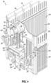
- FIGS. 3-6B illustrate an exemplary embodiment of the basket 16.
- the shape of the basket is defined by the basket frame 70.
- the basket frame 70 is made up of a series of connected panels-the front panel 72, the back panel 74, and two side panels 76.
- the panels 72, 74, 76 are connected to each other at or near their sides edges.
- the front panel 72 is connected at one edge to a side panel 76 and at an opposing edge to a different side panel 76.
- the back panel 74 is connected at one edge to a side panel 76 and at an opposing edge to a different side panel 76.
- the panels 72, 74, 76 form a rectangular cuboid shape with two opposing open faces-the top and the bottom of the basket frame 70. It is to be understood that other constructions and shapes of the basket 16 are possible. Further, it is to be understood that the front 72, back 74, and side panels 76 could be different sizes from one another depending on a user's needs or preferences. For example, FIG. 3 shows that the side panels 76 of the basket 16 are significantly shorter than the front and back panels 72, 74. In the pictured embodiment, the side panels 76 are shortened to allow for the addition of angled panels 78, described in further detail below. Regardless of the shape or construction of the basket frame 70, the interior of the connected panels 72, 74, 76 defines the bounds of a storage space 80 therein. The storage space 80 is used to, for example, hold food product 14.
- each angled panel 78 is roughly L-shaped. It is to be understood that the angled panels 78 could be differently shaped and still perform the function described herein.
- An angled panel 78 is coupled to and extends from each of the side panels 76. Specifically, an angled panel 78 extends downwardly from a side panel 76 and then extends inwardly, towards a center of the basket 16 along a bottom face of the basket 16. The angled panels 78 are coupled to the side panels 76 and are configured to pivot about their couplings 82-between a closed position and an open position.
- the edges of the angled panels 78 are approximately coextensive with the edges of the front and back panels 72, 74 such that they, collectively, define a closed bottom of the storage space 80. Further, the edges of the angled panels 78 meet each other roughly in the middle of the bottom face of the basket 16. Thus, in the closed position the angled panels 78 form the bounds for the bottom and part of the sides of the basket 16 to prevent food product 14 from falling out of the basket 16. Transitioning from the closed position to the open position, the angled panels 78 pivot about their couplings 82 to extend outwardly from the side panels 76 to form an opening in at least the bottom of the basket 16.
- the opening may also extend to the side of the basket 16 depending on where the angled panels 78 are coupled to the side panels 76. Regardless, with the angled panels 78 in the open position food product 14 in the basket 16 will exit the basket 16 through an opening in at least the bottom of the basket 16 formed by the absence of the angled panels 78 (e.g., the angled panels 78 no longer form a bottom of the basket 16).
- the baskets 16 are configured such that food product 14 will exit the basket 16 in less than 10 seconds. Specifically, the baskets 16 are configured to be emptied of food product 14 in less than 5 seconds. Such rapid evacuation of the food product 14 from the basket 16 when the angled panels 78 transition from the closed position to the open position offers an advantage over some other baskets known in the art.
- a product discharge mechanism 84 is positioned on the front panel 72 of the basket 16.
- the product discharge mechanism 84 functions to control the position of the angled panels 78-which in turn determines if and when the basket 16 will discharge food product 14.
- the product discharge mechanism 84 is responsible for changing the position of the angled panels 78 from a closed position to an open position and vice versa.
- the product discharge mechanism 84 is coupled to both of the angled panels 78 such that actuating the product discharge mechanism 84, in turn, causes the angled panels 78 to change position (e.g., from closed to open or vice versa).
- the product discharge mechanism 84 is biased to keep the angled panels 78 in the closed position until the product discharge mechanism 84 is actuated.
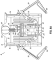
- FIG. 5A shows a bracket 112 fastened to the front surface of the front panel 72.
- the bracket 112 serves as a guide for the member 86-particularly, for the rod 106 of the member 86.
- the bracket 112 can serve as a resting surface for the shoulder 90 when the product discharge mechanism 84 has not been actuated.
- the bracket 112 further features a stopper 114 to prevent the U-shaped enclosure 100 and collar 94 from travelling too far upwards when the product discharge mechanism 84 is actuated.
- the stopper 114 can be in the form of a bolt or other mechanical fastener fastened to the bracket 112. It is to be understood that the stopper 114 could take on other forms as well.
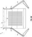
- FIG. 5B shows the rear of the basket 16 when the angled panels 78 are in the closed position.
- FIG. 6A the Figure shows the front of the basket 16-and specifically the product discharge mechanism 84-when the angled panels 78 are in an open position.
- the member 86 moves upwards.
- the collar 94 and U-shaped enclosure 100 approach and may contact the stopper 114 attached to the bracket 112.
- the shoulder 90 previously near or resting on the surface of the bracket 112, moves upwards away from the bracket 112 and the biasing element 88 is compressed between the pickup point 68 and the shoulder 90.
- FIG. 6B shows the rear of the basket 16 when the angled panels 78 are in the open position.
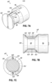
- the neck portion 118 is the part of the pickup point 68 intended to be gripped, for example, by the clamping gripper 66. Extending outwardly from the neck portion 118 is the cylindrical head portion 120. In an embodiment, the head portion 120 is greater in diameter than the neck portion 118. Further, the head portion 120 may be similar in diameter to the main body 116. The neck portion 118 being smaller in diameter than the main body 116 and the head portion 120 is intended to make it easier to grip the neck portion 118. Further, the main body 116 and the head portion 120 may be tapered inwards towards the neck portion 118 to further aid in gripping the neck portion 118. Moreover, tapered portions 122 of the main body 116 and head portion 120 will help to correct potential misalignment of the clamping gripper 66 when the clamping gripper 66 initiates contact with the pickup point 68.
- the pickup point 68 includes additional features to increase the stability of the basket 16 when picked up and transported via the pickup point 68.
- the neck portion 118 of the pickup point 68 features a flat surface 124 located along a chord of a cross-section of the neck portion 118.
- the flat surfaces 124 may be located on the top and bottom of the neck portion 118. The flat surfaces 124 help to prevent the pickup point 68 from rotating within the grip of the clamping gripper 66 when picked up to the transported by offering space for the jaws 126 of the clamping gripper 66 to rest.
- dowels 128 are added on the top and bottom of the pickup point 68.
- the dowels 128 may extend over the flat surfaces 124.
- the dowels 128 extend from the head portion 120 to the main body 116 thereby spanning the neck portion 118.
- the dowels 128 provide a further feature for the clamping gripper 66 to rest against to prevent the pickup point 68 from rotating within the clamping gripper 66.
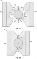
- FIGS. 8A and 8B show engagement between the clamping gripper 66 of the gantry 24 and the pickup point 68 of a basket 16 in accordance with the embodiments of this invention.
- the gantry system 22 includes a gantry 24 which, in turn, includes a clamping gripper 66.
- the clamping gripper 66 is a two-piece clamping mechanism which engages with the pickup point 68 of a basket 16 from opposing sides.
- the clamping gripper 66 includes a pair of jaws 126.
- the jaws 126 are C-shaped and spaced apart from each other a distance equal to or greater than the diameter of the head portion 120 of the pickup point 68.
- Each jaw 126 of the pair of jaws 126 is arranged on a side of the pickup point 68.
- each jaw 126 engages with a side of the pickup point 68 to snugly sandwich the pickup point 68 between the C-shaped jaws 126-thereby securing the pickup point 68 in the clamping gripper 66.
- the interior edges of each of the jaws 126 can be contoured to facilitate easier gripping of the pickup point 68.
- the jaws 126 may similarly be fashioned to allow for the clamping gripper 66 to correct for slight errors in alignment between the basket 16 and the clamping gripper 66.
- Such tapering and contouring makes it easier for the jaws 126 of the clamping gripper 66 to engage with the pickup point 68, even when the pickup point 68 and clamping gripper 66 are not perfectly aligned.
- the engagement of the clamping gripper 66 and the pickup point 68 defines a single-location engagement between the gantry 24 and the basket 16 in this embodiment.
- the two-piece clamping gripper 66 is clamped into engagement with the pickup point 68.
- the clamping gripper 66 may be pneumatically powered. However, it is to be understood that the clamping gripper 66 could be alternatively powered-hydraulically or electrically, for example.
- the clamping gripper 66 clamps in engagement with the pickup point 68 in such a way to prevent the basket 16 from uncontrollably rotating when the basket 16 is engaged with the gantry 24 (e.g., when the basket 16 is being moved from one position to another).
- This engagement of the clamping gripper 66 and the pickup point 68 improves the operation of the gantry 24 and the basket 16 as compared to prior known designs for these reasons, while also enabling just a single pickup point on the basket 16 to be used in this system 10, thereby simplifying the structure needed.
- the pickup point 68 includes dowels 128 that span the distance from the head portion 120 to the main body 116 (above and below the neck portion 118) as well as flat surfaces 124 on the neck portion 118 that provide for more secure engagement between the clamping gripper 66 and the pickup point 68.
- the jaws 126 of the clamping gripper 66 engage with the dowels 128 and flat surfaces 124 to help avoid any undesirable or uncontrolled pivoting of the basket 16 during engagement and movement with the gantry 24.
- preventing uncontrolled rotational movements of the basket 16 during engagement with the gantry 24 serves to prevent a basket 16 engaged with the gantry 24 from impacting other baskets 16 at the system 10 or fryer 12, thereby preventing damage to baskets 16, the gantry 24, the fryer 12, or the system 10, as well as preventing food product spills and/or cycle delays associated with such spills and impacts.
- the improved speed and basket workflow management is therefore enabled in part by this engagement of baskets 16 with the gantry 24.
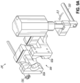
- the Figures show a portion of the gantry 24 in greater detail. Specifically, the Figures show the relationships between clamping gripper 66, actuator arm 130, and basket detection device 132.
- the clamping gripper 66, actuator arm 130, and basket detection device 132 work in concert to allow for the gantry 24 to pick up and transport baskets 16 as well as to dispense food product 14.
- the actuator arm 130 is in the form of an elongated rod that is generally cylindrically shaped, attached to the gantry 24, and located on a side of the clamping gripper 66 and the basket detection device 132 is located on an opposing side of the clamping gripper 66. It is to be understood that alternative arrangements are envisioned.
- FIG. 9A shows the actuator arm 130 in a retracted position.
- the actuator arm 130 In the retracted position, the actuator arm 130 is held away from the basket 16 (e.g., rotated 90° out of the way) to prevent inadvertent contact with the basket 16 that could cause uncontrolled and/or unintended movement and/or openings of the basket 16.
- Arrow A3 illustrates the transition of the actuator arm 130 from the retracted position to the extended position. In transitioning to the extended position, the actuator arm 130 rotates and moves upwardly with a force to engage with the product discharge mechanism 84.
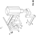
- FIG. 9B shows the actuator arm 130 in the extended position.
- the actuator arm 130 In the extended position, the actuator arm 130 is positioned to interact with the product discharge mechanism 84 to cause the basket 16 to dispense food product 14. Such interaction is described in greater detail with respect to FIGS. 10A and 10B .
- Arrow A4 illustrates the transition of the actuator arm 130 from the extended position to the retracted position. Pneumatic power is used to move the actuator arm 130 from the retracted position to the extended position and back, as demonstrated by arrows A3 (in FIG. 9A ) and A4 (in FIG. 9B ). It is to be understood that the actuator arm 130 could be alternatively powered-hydraulically or electrically, for example.
- the basket detection device 132 is attached to the gantry 24 and is configured to detect the presence of a basket 16 when a basket 16 is located in front of the clamping gripper 66.
- the basket detection device 132 is used to line up the jaws 126 of the clamping gripper 66 with the pickup point 68 of the basket 16.
- the basket detection device 132 can take on many forms.
- the basket detection device 132 is shown as a laser.
- the basket detection device 132 could also be a proximity switch or a torque sensor. Further, it is to be understood that the basket detection device 132 could take on other forms besides those explicitly described herein.
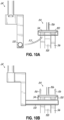
- FIGS. 10A and 10B the Figures show the interaction between the actuator arm 130 of the gantry 24 and the product discharge mechanism 84 of the basket 16.
- the actuator arm 130 is in the retracted position-held away from the basket 16 to prevent inadvertent contact with the basket 16.
- Arrow A5 illustrates the path that the actuator arm 130 will take to interact with the product discharge mechanism 84.
- the actuator arm 130 will rotate 90° towards the basket 16 and move upwards with a force to meet and lift the collar 94, thereby overcoming the bias (e.g., spring bias) of the biasing element 88.
- Such actions can happen concurrently or in individual stages.
- FIG. 10B shows the actuator arm 130 in the extended position and interacting with the product discharge mechanism 84.
- the actuator arm 130 is interacting with an underside of the U-shaped enclosure 100 of the L-shaped plate 96 and raising the U-shaped enclosure 100 (and thus the collar 94 contained therein) upwards-as indicated by arrows A6.
- the actuator arm 130 could interact with other parts of the product discharge mechanism 84 in alternate embodiments.
- the actuator arm 130 could interact directly with the collar 94 in the absence of a U-shaped enclosure 100 in an alternative embodiment.
- the transition of the actuator arm 130 from the retracted position to the extended position and the corresponding interaction with the product discharge mechanism 84 actuates the product discharge mechanism 84.
- the angled panels 78 are moved to an open position from a closed position so that food product 14 can be evacuated from the basket 16 (as described in greater detail above).
- FIGS. 11A-11G show a series of steps defining a basket loading cycle and a basket discharge cycle according to embodiments of this invention, each of which may be repeatedly performed to manage basket workflow at the cooking system 10.
- the newly-developed basket-gantry interface of the system 10 described herein helps achieve more reliable and precise movements of the baskets 16 and a quicker cycle time for automated cooking of various food products.
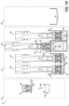
- FIG. 11A the Figure shows a basket 16 filled with cooked food product 14 sitting on a platform 46 after exiting a fryer vat 42.
- the vertical transport assembly 60 lifts the platform 46 on which the basket 16 sits, thus raising the basket 16 from the fryer vat 42 and out of the heated cooking medium 44, as shown, for example, by arrow A7.
- the basket 16 is waiting to be picked up by the gantry 24, which is shown positioned by the dispensing freezer 18 in FIG. 11A .
- the gantry 24 receives a signal from the gantry control 26 and/or system controller 25, the gantry 24 will move to the platform 46 holding the filled basket 16 and engage the basket 16, as described in greater detail below with reference to FIG. 11B .
- the Figure shows a basket 16 in the basket movement receptacle 64 located at the filling location.
- the dispenser freezer 18 dispenses uncooked food product 14 into the basket 16 in preparation of transport by the gantry 24 to a fryer 12.
- the Figure shows the gantry 24, after receiving a signal from the gantry control 26 and/or system controller 25, engaging with the filled basket 16 on the platform 46.
- the gantry 24 can employ a basket detection device 132 (e.g., proximity switch, torque sensor, laser, etc.) configured to detect the presence of a basket 16 in front of the clamping gripper 66.
- the basket detection device 132 is addressed in greater detail above with respect to FIGS. 9A and 9B .
- the gantry 24 activates the jaws 126 (e.g., pneumatically) of the clamping gripper 66 and secures the pickup point 68 of the basket 16 between the jaws 126.
- the engagement of the jaws 126 with the pickup point 68 is described in greater detail with respect to FIGS. 8A and 8B .
- the clamping gripper 66 is configured to prevent uncontrolled rotational movements of the basket 16 when the basket 16 is transported. Such helps to avoid impacts of the basket 16 with other elements (e.g., other baskets 16, parts of the fryer 12, etc.) of the automated cooking system 10.
- FIG. 11C the Figure shows the basket 16 filled with cooked food product 14 suspended by the gantry 24 in a position at a height above the hot holding station 20. Further, FIG. 11C shows the gantry 24, upon receiving a signal from the gantry control 26 and/or system control 25, actuating the filled basket 16 to open the bottom of same and thereby discharge the cooked food product 14 into the hot holding receiving area 30 of the hot holding station 20, as shown by arrow A8. Actuation of the product discharge mechanism 84 is described in greater detail above with reference to FIGS. 10A and 10B ; however, in short the actuator arm 130 of the gantry 24 interacts with the product discharge mechanism 84 to cause the basket 16 to discharge the cooked food product 14 contained therein.
- the gantry 24 can vary the height above the hot holding station 20 at which this discharge step occurs depending on the specific type of food product 14 contained within the basket 16. For example, one cooked food product 14 may be discharged at a first height while a different cooked food product 14 may be discharged at a different, second height either higher or lower than the first height. Further, cooked food product 14 may be discharged while the basket 16 is moving from a first height to a second height, as shown by arrow A15. Such is helpful if the cooked food product 14 is long and fragile, for example, to prevent the cooked food product 14 from getting damaged by the basket 16 or by the drop impact into the hot holding station 20. Regardless of the discharge height, after discharge from the basket 16 the cooked food product 14 is then held in the hot holding receiving area 30 for further preparation and packaging by an operator.
- the Figure shows the staging shelf 62 preparing for the arrival of an empty basket 16.
- the gantry control 26 and/or system controller 25 sends a signal to the staging shelf 62 so that the staging shelf 62 pivots into a (generally horizontal) deployed position from a stowed position (e.g., as shown in FIGS. 11A and 11B ), as illustrated by arrow A9.
- the staging shelf 62 With the staging shelf 62 in the deployed position, the staging shelf 62 is ready to receive an empty basket 16 from the gantry 24.
- the Figure shows the gantry 24, at the direction of the gantry control 26 and/or system controller 25, transporting the basket 16 from a position above the hot holding station 20 (after discharging cooked food product 14) to the staging shelf 62.
- the gantry 24 disengages with the basket 16 and leaves the basket 16 on the staging shelf 62.
- the empty basket 16 is then ready to be engaged by the gantry 24 again later when customer demand necessitates.
- FIG. 11D shows a basket 16 in the basket movement receptacle 64 being transported, as indicated by arrow A10.
- the basket movement receptacle 64 moves (if necessary) the basket 16 into a pickup position such that the basket 16 is ready to be engaged by the gantry 24. It is to be understood that the filling location and the pickup location may be the same position and thus movement from the filling location to the pickup location may be unnecessary.
- the filled basket 16 waits in the basket movement receptacle 64 until the basket 16 is engaged by the gantry 24, as shown in FIG. 11E . These movements can occur simultaneous to other actions being taken by the gantry 24 at the fryer 12.
- FIG. 11E the Figure shows a basket 16 filled with uncooked food product 14 in the basket movement receptacle 64, located in a pickup position adjacent the dispensing freezer 18, being engaged by the gantry 24.
- the gantry 24 moves downwardly to the basket movement receptacle 64 to engage the next basket 16.
- Which platform 46 the basket 16 should be moved to is typically determined by the system controller 25. Note that although a filled basket 16 was previously shown in FIG. 11A at the platform 46 where the gantry 24 places the new basket 16 in FIG. 11F , any available appropriate and available platform 46 could be utilized.
- the gantry 24 disengages with the basket 16 and leaves the basket 16 on the platform 46 above the fryer vat 42.
- the platforms 46, on which the baskets 16 sit, are attached to the vertical transport assemblies 60.
- the vertical transport assembly 60 Upon receiving a signal to initiate a cooking cycle from the system controller 25, the vertical transport assembly 60 then lowers the basket 16, filled with uncooked food product 14, into a cooking medium 44 for a cooking cycle, as shown by arrow A11. These actions can automatically occur at the cooking system 10 while the gantry 24 moves to perform actions on other baskets 16 and platforms 46.
- FIG. 11F shows the basket movement receptacle 64 moving upwards, as shown by arrow A12, towards the staging shelf 62 in order to transfer the empty basket 16 on the staging shelf 62 from the staging shelf 62 to the basket movement receptacle 64.
- the staging shelf 62 can be pivoted to the generally vertical, stowed position to complete the transfer of the basket 16 into the basket movement receptacle 64.
- FIGS. 11A-11G show features of the system's 10 basket loading and discharge cycles for managing basket 16 workflow during food preparation at an automated cooking system 10.
- the automated cooking system 10 prioritizes and orders the basket loading cycles and basket discharge cycles for the gantry system 22 to satisfy varying levels of demand for cooked food product 14 from the automated cooking system 10.
- This arrangement allows for successful management of up to 6 or more baskets 16 cooking food product 14 simultaneously at the fryer 12, which can result, for example, in throughput levels of 150 pounds of cooked French fries an hour in one operational example.
- These operational throughput levels are enabled at least in part by the innovative basket-gantry interface described in this application.
- the basket loading and basket discharge cycles could include additional or fewer steps in other embodiments.
- the gantry 24 is configured to manage the workflow of 6 or more baskets 16 and cooking stations (platforms 46) at the fryer 12 simultaneously to provide an increased maximum cooking volume throughput of the cooking system 10.
- the automatic cooking system 10 therefore improves the field of cooking equipment and methodologies by limiting the need for operator intervention (and associate expense) while maximizing how much food product 14 can be cooked and prepared within the standard space used by fryers in commercial setting kitchens.
- the design of the gantry 24 in this cooking system 10 advantageously controls the baskets 16 during the rapid movements of the basket loading and discharge cycles to avoid uncontrolled pivoting or rotations and/or undesired impacts with other baskets 16 held at the cooking system 10.
- the automated cooking system 10 allows the operator to perform other tasks while the automated cooking system 10 is working. Additionally, an automated cooking system 10 allows for improved quality control of the food product 14 (e.g., precise cooking time, more precise weight of product being cooked, optimized heat management by alternating product drops between the various cooking chambers, or synchronized mini-filtration during idle periods). Additionally, the automated cooking system 10 increases the hourly product throughput versus a manually-operated system. Further, the automated cooking system 10 provides superior up-time and predictive fault diagnostics due to continual baseline performance comparisons and configurable warning thresholds.
- routines executed by the system controller 25 (or a series of control elements as noted above in alternative embodiments), shown for example in FIG. 1 , to implement the embodiments of the invention, whether implemented as part of an operating system or a specific application, component, program, object, module, or sequence of instructions, or a subset thereof, may be referred to herein as "computer program code,” or simply "program code.”
- Program code typically comprises computer-readable instructions that are resident at various times in various memory and storage devices in a computer and that, when read and executed by one or more processors in a computer, cause that computer to perform the operations necessary to execute operations or elements embodying the various embodiments of the invention.
- Computer-readable program instructions for carrying out operations of the embodiments of the invention may be, for example, assembly language or either source code or object code written in any combination of one or more programming languages.
- the program code embodied in any of the applications or modules described herein is capable of being individually or collectively distributed as a program product in a variety of different forms.
- the program code may be distributed using a computer-readable storage medium having computer-readable program instructions thereon for causing a processor to carry out the embodiments of the invention.
- Computer-readable storage media which is inherently non-transitory, may include volatile, non-volatile, removable, and non-removable tangible media implemented in any method or technology for storage of information, such as computer-readable instructions, data structures, program modules, or other data.
- Computer-readable storage media may further include RAM, ROM, erasable programmable read-only memory (EPROM), electrically erasable programmable read-only memory (EEPROM), flash memory or other solid state memory technology, portable compact disc read-only memory (CD-ROM), or other optical storage, magnetic cassettes, magnetic tape, magnetic disk storage or other magnetic storage devices, or any other medium that can be used to store the desired information and which can be read by a computer.
- a computer-readable storage medium should not be construed as transitory signals per se (e.g., radio waves or other propagating electromagnetic waves, electromagnetic waves propagating through a transmission media such as a waveguide, or electrical signals transmitted through a wire).
- Computer-readable program instructions may be downloaded to a computer, another type of programmable data processing apparatus, or another device from a computer-readable storage medium or to an external computer or external storage device via a network.
- Computer-readable program instructions stored in a computer-readable medium may be used to direct a computer, other types of programmable data processing apparatuses, or other devices to function in a particular manner, such that the instructions stored in the computer-readable medium produce an article of manufacture including instructions that implement the functions, acts, or operations specified in the flow-charts, sequence diagrams, or block diagrams.
- the computer program instructions may be provided to one or more processors of a general purpose computer, a special purpose computer, or another programmable data processing apparatus to produce a machine, such that the instructions, which execute via the one or more processors, cause a series of computations to be performed to implement the functions, acts, or operations specified in the flow-charts, sequence diagrams, or block diagrams.
Landscapes
- Engineering & Computer Science (AREA)
- Food Science & Technology (AREA)
- Frying-Pans Or Fryers (AREA)
- Warehouses Or Storage Devices (AREA)
Applications Claiming Priority (4)
| Application Number | Priority Date | Filing Date | Title |
|---|---|---|---|
| US17/244,096 US11678769B2 (en) | 2021-04-29 | 2021-04-29 | Automated cooking system and methods of managing basket workflow for food preparation |
| US17/344,063 US12262847B2 (en) | 2021-04-29 | 2021-06-10 | Automated cooking system and method using basket-gantry interface |
| US17/686,816 US12465173B2 (en) | 2021-04-29 | 2022-03-04 | Automated cooking system with lift platforms |
| EP22168777.5A EP4082411B1 (fr) | 2021-04-29 | 2022-04-19 | Système de cuisson automatique et procédé utilisant une interface panier-portique |
Related Parent Applications (1)
| Application Number | Title | Priority Date | Filing Date |
|---|---|---|---|
| EP22168777.5A Division EP4082411B1 (fr) | 2021-04-29 | 2022-04-19 | Système de cuisson automatique et procédé utilisant une interface panier-portique |
Publications (2)
| Publication Number | Publication Date |
|---|---|
| EP4487743A2 true EP4487743A2 (fr) | 2025-01-08 |
| EP4487743A3 EP4487743A3 (fr) | 2025-05-07 |
Family
ID=81325341
Family Applications (6)
| Application Number | Title | Priority Date | Filing Date |
|---|---|---|---|
| EP22168777.5A Active EP4082411B1 (fr) | 2021-04-29 | 2022-04-19 | Système de cuisson automatique et procédé utilisant une interface panier-portique |
| EP24208094.3A Pending EP4487743A3 (fr) | 2021-04-29 | 2022-04-19 | Système et procédé de cuisson automatisée utilisant une interface panier-fourier |
| EP22168774.2A Active EP4082410B1 (fr) | 2021-04-29 | 2022-04-19 | Système de cuisson automatique avec des plateformes de levage |
| EP23210458.8A Active EP4316321B1 (fr) | 2021-04-29 | 2022-04-28 | Procédé de gestion de flux de travail de panier pour préparation d'aliments |
| EP22170595.7A Active EP4082412B1 (fr) | 2021-04-29 | 2022-04-28 | Système de cuisson automatique et procédés de gestion de flux de travail de panier pour la préparation d'aliments |
| EP23210456.2A Active EP4316320B1 (fr) | 2021-04-29 | 2022-04-28 | Système de cuisson automatisé et procédés de gestion de flux de travail de panier pour préparation d'aliments |
Family Applications Before (1)
| Application Number | Title | Priority Date | Filing Date |
|---|---|---|---|
| EP22168777.5A Active EP4082411B1 (fr) | 2021-04-29 | 2022-04-19 | Système de cuisson automatique et procédé utilisant une interface panier-portique |
Family Applications After (4)
| Application Number | Title | Priority Date | Filing Date |
|---|---|---|---|
| EP22168774.2A Active EP4082410B1 (fr) | 2021-04-29 | 2022-04-19 | Système de cuisson automatique avec des plateformes de levage |
| EP23210458.8A Active EP4316321B1 (fr) | 2021-04-29 | 2022-04-28 | Procédé de gestion de flux de travail de panier pour préparation d'aliments |
| EP22170595.7A Active EP4082412B1 (fr) | 2021-04-29 | 2022-04-28 | Système de cuisson automatique et procédés de gestion de flux de travail de panier pour la préparation d'aliments |
| EP23210456.2A Active EP4316320B1 (fr) | 2021-04-29 | 2022-04-28 | Système de cuisson automatisé et procédés de gestion de flux de travail de panier pour préparation d'aliments |
Country Status (3)
| Country | Link |
|---|---|
| US (1) | US12465173B2 (fr) |
| EP (6) | EP4082411B1 (fr) |
| AU (3) | AU2022202195A1 (fr) |
Families Citing this family (2)
| Publication number | Priority date | Publication date | Assignee | Title |
|---|---|---|---|---|
| WO2025240844A1 (fr) * | 2024-05-16 | 2025-11-20 | Charter House Holdings, Llc | Système robotique à bras multiples pour la cuisson de produits alimentaires et son procédé d'utilisation |
| CN118542483B (zh) * | 2024-07-29 | 2024-10-15 | 山东德州扒鸡股份有限公司 | 一种智能自动控制的扒鸡煮制设备 |
Family Cites Families (55)
| Publication number | Priority date | Publication date | Assignee | Title |
|---|---|---|---|---|
| US3164406A (en) | 1960-09-07 | 1965-01-05 | Leonard D Barry | Automatic holding device |
| US4722267A (en) | 1986-03-24 | 1988-02-02 | Longin Galockin | French fry vending machine |
| US4901633A (en) | 1987-09-28 | 1990-02-20 | De Longhi S.P.A. | Rotating oblique basket frier for cyclic immersion cooking |
| JPS63288117A (ja) | 1987-05-21 | 1988-11-25 | 有限会社 高橋商店 | 自動油揚げフライヤ |
| US5172328A (en) | 1988-04-01 | 1992-12-15 | Restaurant Technology, Inc. | Food preparation system and method |
| US4913038A (en) | 1988-08-03 | 1990-04-03 | Henny Penny Corporation | Deep fat fryer with computerized control system |
| US5112633A (en) | 1989-01-13 | 1992-05-12 | Heat And Control, Inc. | Automatic stirring of batch fried food products |
| US4951558A (en) | 1989-04-03 | 1990-08-28 | Figliuzzi Vincent D | Basket lifting mechanism for cooking pot |
| US5224415A (en) | 1989-12-29 | 1993-07-06 | Gas Research Institute | Frozen food storage and dispensing system |
| US5142968A (en) | 1989-12-29 | 1992-09-01 | Arthur D. Little, Inc. | Automated deep fat fryer |
| US5191918A (en) | 1990-05-04 | 1993-03-09 | Restaurant Technology, Inc. | Food dispenser and method |
| US5232151A (en) | 1992-01-02 | 1993-08-03 | Henny Penny Corporation | Cold zone heat regulation device and method for a deep fat fryer |
| US5263406A (en) | 1993-03-02 | 1993-11-23 | Chiu Yao Jui | Vacuum type food frying apparatus |
| US5973297A (en) | 1996-03-28 | 1999-10-26 | Henny Penny Corporation | Apparatus and method for heat regulation of deep fat fryer |
| US6165525A (en) | 1998-08-12 | 2000-12-26 | Reno Rolle | Food cooking system with ultrasonic rotational basket |
| CA2279957A1 (fr) | 1999-08-09 | 2001-02-09 | Speed Fry Corporation | Dispositif et methode de friture automatique d'aliments |
| US9202206B2 (en) | 2000-09-25 | 2015-12-01 | Ecardless Bancorp, Ltd. | Secure financial transaction processing using location information |
| US7100497B2 (en) | 2001-09-12 | 2006-09-05 | Pitco Frialator, Inc. | High temperature, oil saving, rapid cook fryer system |
| US20030192435A1 (en) | 2002-04-11 | 2003-10-16 | Mcnair John Duncan | Cooking appliance |
| US6869633B2 (en) | 2002-04-22 | 2005-03-22 | Restaurant Technology, Inc. | Automated food frying device and method |
| US7441388B2 (en) | 2002-04-22 | 2008-10-28 | Restaurant Technology, Inc. | Automated device for packaging food |
| US20030205028A1 (en) | 2002-04-22 | 2003-11-06 | Sus Gerald A. | Automated food processing system and method |
| US20030205147A1 (en) | 2002-04-22 | 2003-11-06 | Glenn Schackmuth | Conveyor system and method for packaged food |
| US20040060456A1 (en) | 2002-09-26 | 2004-04-01 | Chung Jing-Yau | Multi-level batch fryer for alternative wok cooking |
| US6588325B1 (en) | 2002-10-31 | 2003-07-08 | Pitco Frialator, Inc. | Deep fat fryer lifting assembly |
| US20110203570A1 (en) | 2005-08-08 | 2011-08-25 | Popeil Ronald M | Device to efficiently cook foods using liquids and hot vapors |
| US20120167778A1 (en) | 2005-08-08 | 2012-07-05 | Popeil Ronald M | Device to efficiently cook foods using liquids and hot vapors |
| US8850965B2 (en) | 2005-08-08 | 2014-10-07 | Ronald M. Popeil | Device to efficiently cook food |
| US20140227411A1 (en) | 2005-08-08 | 2014-08-14 | Ron's Enterprise, Inc. | Device to efficiently cook foods using liquids and hot vapors |
| US20070214968A1 (en) | 2006-03-20 | 2007-09-20 | Prince Castle Inc. | Fry basket |
| US7775156B2 (en) | 2006-04-28 | 2010-08-17 | Restaurant Technology, Inc. | Fry basket for processing of bulk food items and method |
| US20080121578A1 (en) | 2006-11-27 | 2008-05-29 | Henny Penny Corporation | Automatic cooking medium filtering systems and methods |
| US20080237104A1 (en) | 2007-03-29 | 2008-10-02 | Paul Lincoln Foster | Fryer device |
| US8065954B2 (en) | 2007-03-29 | 2011-11-29 | Spinfry, Inc. | Cooking device |
| US8037812B1 (en) | 2007-05-02 | 2011-10-18 | Sumner Sr Douglas Arthur | Bottom opening fryer basket |
| US20090084273A1 (en) | 2007-09-27 | 2009-04-02 | The Frymaster Corporation Llc | Low oil volume fryer with automatic filtration and top-off capability |
| US8549993B2 (en) | 2008-04-14 | 2013-10-08 | Spinfry, Inc. | Cooking device with slidable drawer |
| US20100037782A1 (en) | 2008-08-18 | 2010-02-18 | Spinfry, Inc. | Fryer device with oil removal and conveyor system |
| IT1390860B1 (it) | 2008-09-29 | 2011-10-19 | De Longhi Spa | Friggitrice e procedimento di cottura |
| US8551331B2 (en) | 2009-05-29 | 2013-10-08 | Henny Penny Corporation | Automatic cooking medium filtering systems and methods |
| KR100984964B1 (ko) | 2010-03-15 | 2010-10-04 | 주식회사 파세코 | 튀김기 |
| US8584579B1 (en) | 2011-09-29 | 2013-11-19 | Prh1, Llc | Bottom opening fryer basket |
| WO2013082676A1 (fr) | 2011-12-08 | 2013-06-13 | Breville Pty Limited | Procédé et appareil pour friteuse |
| KR101288282B1 (ko) | 2012-12-28 | 2013-07-26 | 조혜수 | 리프트형 튀김장치 |
| KR20150027942A (ko) | 2013-09-05 | 2015-03-13 | 한태희 | 자동 요리 기기 표준화 사업 |
| CN106304818B (zh) | 2015-06-10 | 2020-09-11 | 台达电子工业股份有限公司 | 外转子式风扇结构 |
| EP3150092A1 (fr) | 2015-10-02 | 2017-04-05 | Franke Technology and Trademark Ltd | Appareil de preparation automatisee de produits alimentaires cuits |
| BE1023936B9 (nl) | 2016-03-09 | 2017-10-27 | Syral Belgium Nv | Vochtig huisdiervoer dat een eiwitachtige vleesanaloog met een verbeterde textuur omvat |
| KR20170064979A (ko) | 2016-07-18 | 2017-06-12 | 전범주 | 자동 튀김장치 |
| CA3071112A1 (fr) | 2017-07-27 | 2019-01-31 | Watlow Electric Manufacturing Company | Systeme de capteur et ensemble capteur-dispositif de chauffage integre pour mesurer et commander les performances d'un systeme de chauffage |
| WO2019108909A1 (fr) | 2017-11-30 | 2019-06-06 | Henny Penny Corporation | Friteuse automatisée avec portique en hauteur et procédés de préparation d'aliments |
| WO2019136406A1 (fr) | 2018-01-08 | 2019-07-11 | Robert Almblad | Système de friteuse automatique à système de distribution d'aliments délaminant |
| WO2019213087A1 (fr) | 2018-05-01 | 2019-11-07 | Pitco Frialator, Inc. | Dispositif de levage de panier de friteuse à panier automatisé |
| US11192258B2 (en) | 2018-08-10 | 2021-12-07 | Miso Robotics, Inc. | Robotic kitchen assistant for frying including agitator assembly for shaking utensil |
| CN111627163A (zh) * | 2020-05-14 | 2020-09-04 | 广东智源机器人科技有限公司 | 煎炸控制方法、设备及装置 |
-
2022
- 2022-03-04 US US17/686,816 patent/US12465173B2/en active Active
- 2022-03-31 AU AU2022202195A patent/AU2022202195A1/en active Pending
- 2022-03-31 AU AU2022202198A patent/AU2022202198A1/en active Pending
- 2022-03-31 AU AU2022202201A patent/AU2022202201A1/en active Pending
- 2022-04-19 EP EP22168777.5A patent/EP4082411B1/fr active Active
- 2022-04-19 EP EP24208094.3A patent/EP4487743A3/fr active Pending
- 2022-04-19 EP EP22168774.2A patent/EP4082410B1/fr active Active
- 2022-04-28 EP EP23210458.8A patent/EP4316321B1/fr active Active
- 2022-04-28 EP EP22170595.7A patent/EP4082412B1/fr active Active
- 2022-04-28 EP EP23210456.2A patent/EP4316320B1/fr active Active
Also Published As
| Publication number | Publication date |
|---|---|
| EP4082411B1 (fr) | 2024-10-23 |
| EP4316320B1 (fr) | 2025-06-04 |
| AU2022202195A1 (en) | 2022-11-03 |
| EP4487743A3 (fr) | 2025-05-07 |
| EP4082410C0 (fr) | 2025-04-16 |
| AU2022202201A1 (en) | 2022-11-17 |
| EP4316320C0 (fr) | 2025-06-04 |
| EP4316321C0 (fr) | 2025-10-29 |
| US12465173B2 (en) | 2025-11-11 |
| EP4082412B1 (fr) | 2024-06-05 |
| EP4082410A1 (fr) | 2022-11-02 |
| EP4316321A2 (fr) | 2024-02-07 |
| AU2022202198A1 (en) | 2022-11-17 |
| EP4082411C0 (fr) | 2024-10-23 |
| EP4082412A1 (fr) | 2022-11-02 |
| EP4316321A3 (fr) | 2024-04-10 |
| EP4082410B1 (fr) | 2025-04-16 |
| EP4316320A3 (fr) | 2024-04-03 |
| EP4082412C0 (fr) | 2024-06-05 |
| US20220346597A1 (en) | 2022-11-03 |
| EP4082411A1 (fr) | 2022-11-02 |
| EP4316320A2 (fr) | 2024-02-07 |
| EP4316321B1 (fr) | 2025-10-29 |
Similar Documents
| Publication | Publication Date | Title |
|---|---|---|
| EP4487743A2 (fr) | Système et procédé de cuisson automatisée utilisant une interface panier-fourier | |
| CA1312212C (fr) | Methode et systeme de confection culinaire | |
| EP1107199B1 (fr) | Machine de vente pour distribution de pizzas chaudes | |
| US11910957B2 (en) | Automated fryer with selectively activated heating elements | |
| US5132914A (en) | Food preparation system and method | |
| US20250017420A1 (en) | Automated cooking system and method using basket-gantry interface | |
| WO2022205955A1 (fr) | Dispositif et procédé de cuisson intelligents | |
| US20230277009A1 (en) | Automated Pizza-Making Apparatus and Method | |
| US11678769B2 (en) | Automated cooking system and methods of managing basket workflow for food preparation | |
| KR102881308B1 (ko) | 튀김용 조리 기구 | |
| KR102881307B1 (ko) | 튀김물의 기름 제거 장치 | |
| KR102881306B1 (ko) | 로봇을 이용한 무인 자동 튀김 조리 시스템 | |
| KR20210056191A (ko) | 튀김기용 복수개의 튀김바구니 리프팅장치 | |
| CN118340424A (zh) | 一种自动烹饪装置及方法 | |
| JP2026514092A (ja) | バスケット補充システム | |
| WO2025010500A9 (fr) | Système automatisé de préparation d'aliments et/ou de boissons |
Legal Events
| Date | Code | Title | Description |
|---|---|---|---|
| PUAI | Public reference made under article 153(3) epc to a published international application that has entered the european phase |
Free format text: ORIGINAL CODE: 0009012 |
|
| STAA | Information on the status of an ep patent application or granted ep patent |
Free format text: STATUS: THE APPLICATION HAS BEEN PUBLISHED |
|
| AC | Divisional application: reference to earlier application |
Ref document number: 4082411 Country of ref document: EP Kind code of ref document: P |
|
| AK | Designated contracting states |
Kind code of ref document: A2 Designated state(s): AL AT BE BG CH CY CZ DE DK EE ES FI FR GB GR HR HU IE IS IT LI LT LU LV MC MK MT NL NO PL PT RO RS SE SI SK SM TR |
|
| PUAL | Search report despatched |
Free format text: ORIGINAL CODE: 0009013 |
|
| AK | Designated contracting states |
Kind code of ref document: A3 Designated state(s): AL AT BE BG CH CY CZ DE DK EE ES FI FR GB GR HR HU IE IS IT LI LT LU LV MC MK MT NL NO PL PT RO RS SE SI SK SM TR |
|
| RIC1 | Information provided on ipc code assigned before grant |
Ipc: A47J 37/12 20060101AFI20250328BHEP |
|
| STAA | Information on the status of an ep patent application or granted ep patent |
Free format text: STATUS: REQUEST FOR EXAMINATION WAS MADE |
|
| 17P | Request for examination filed |
Effective date: 20251107 |
|
| GRAP | Despatch of communication of intention to grant a patent |
Free format text: ORIGINAL CODE: EPIDOSNIGR1 |
|
| STAA | Information on the status of an ep patent application or granted ep patent |
Free format text: STATUS: GRANT OF PATENT IS INTENDED |
|
| INTG | Intention to grant announced |
Effective date: 20260217 |