EP4487783A1 - Verfahren und system zur funktionserweiterung einer ultraschallbildgebungsvorrichtung - Google Patents
Verfahren und system zur funktionserweiterung einer ultraschallbildgebungsvorrichtung Download PDFInfo
- Publication number
- EP4487783A1 EP4487783A1 EP22929549.8A EP22929549A EP4487783A1 EP 4487783 A1 EP4487783 A1 EP 4487783A1 EP 22929549 A EP22929549 A EP 22929549A EP 4487783 A1 EP4487783 A1 EP 4487783A1
- Authority
- EP
- European Patent Office
- Prior art keywords
- imaging device
- host machine
- integrated
- ultrasonic imaging
- integrated imaging
- Prior art date
- Legal status (The legal status is an assumption and is not a legal conclusion. Google has not performed a legal analysis and makes no representation as to the accuracy of the status listed.)
- Pending
Links
Images


Classifications
-
- A—HUMAN NECESSITIES
- A61—MEDICAL OR VETERINARY SCIENCE; HYGIENE
- A61B—DIAGNOSIS; SURGERY; IDENTIFICATION
- A61B8/00—Diagnosis using ultrasonic, sonic or infrasonic waves
-
- A—HUMAN NECESSITIES
- A61—MEDICAL OR VETERINARY SCIENCE; HYGIENE
- A61B—DIAGNOSIS; SURGERY; IDENTIFICATION
- A61B8/00—Diagnosis using ultrasonic, sonic or infrasonic waves
- A61B8/54—Control of the diagnostic device
-
- A—HUMAN NECESSITIES
- A61—MEDICAL OR VETERINARY SCIENCE; HYGIENE
- A61B—DIAGNOSIS; SURGERY; IDENTIFICATION
- A61B8/00—Diagnosis using ultrasonic, sonic or infrasonic waves
- A61B8/44—Constructional features of the ultrasonic, sonic or infrasonic diagnostic device
- A61B8/4411—Device being modular
-
- A—HUMAN NECESSITIES
- A61—MEDICAL OR VETERINARY SCIENCE; HYGIENE
- A61B—DIAGNOSIS; SURGERY; IDENTIFICATION
- A61B8/00—Diagnosis using ultrasonic, sonic or infrasonic waves
- A61B8/46—Ultrasonic, sonic or infrasonic diagnostic devices with special arrangements for interfacing with the operator or the patient
- A61B8/461—Displaying means of special interest
- A61B8/462—Displaying means of special interest characterised by constructional features of the display
-
- A—HUMAN NECESSITIES
- A61—MEDICAL OR VETERINARY SCIENCE; HYGIENE
- A61B—DIAGNOSIS; SURGERY; IDENTIFICATION
- A61B8/00—Diagnosis using ultrasonic, sonic or infrasonic waves
- A61B8/46—Ultrasonic, sonic or infrasonic diagnostic devices with special arrangements for interfacing with the operator or the patient
- A61B8/461—Displaying means of special interest
- A61B8/465—Displaying means of special interest adapted to display user selection data, e.g. icons or menus
-
- A—HUMAN NECESSITIES
- A61—MEDICAL OR VETERINARY SCIENCE; HYGIENE
- A61B—DIAGNOSIS; SURGERY; IDENTIFICATION
- A61B8/00—Diagnosis using ultrasonic, sonic or infrasonic waves
- A61B8/52—Devices using data or image processing specially adapted for diagnosis using ultrasonic, sonic or infrasonic waves
- A61B8/5215—Devices using data or image processing specially adapted for diagnosis using ultrasonic, sonic or infrasonic waves involving processing of medical diagnostic data
- A61B8/523—Devices using data or image processing specially adapted for diagnosis using ultrasonic, sonic or infrasonic waves involving processing of medical diagnostic data for generating planar views from image data in a user selectable plane not corresponding to the acquisition plane
-
- A—HUMAN NECESSITIES
- A61—MEDICAL OR VETERINARY SCIENCE; HYGIENE
- A61B—DIAGNOSIS; SURGERY; IDENTIFICATION
- A61B8/00—Diagnosis using ultrasonic, sonic or infrasonic waves
- A61B8/56—Details of data transmission or power supply
- A61B8/565—Details of data transmission or power supply involving data transmission via a network
-
- A—HUMAN NECESSITIES
- A61—MEDICAL OR VETERINARY SCIENCE; HYGIENE
- A61B—DIAGNOSIS; SURGERY; IDENTIFICATION
- A61B8/00—Diagnosis using ultrasonic, sonic or infrasonic waves
- A61B8/44—Constructional features of the ultrasonic, sonic or infrasonic diagnostic device
- A61B8/4427—Device being portable or laptop-like
Definitions
- the present application relates to the field of ultrasound imaging, more specifically, it relates to a method for expanding functions of ultrasonic imaging devices and a functionally expandable ultrasound imaging system.
- Ultrasound applications for diagnostic purposes include structural imaging and functional imaging, which are used to visualize the anatomical structure of the object under test and to measure the physiological function of the object under test, respectively.
- Conventional ultrasound imaging technology is widely used in medical practice and serves ultrasound examinations with some fixed classical functions. Due to reasons such as fierce market competition and high capital investment, devices with traditional functions are mainly produced and dominated by large-scale manufacturers in order to gain a higher market share. From another perspective, the application areas of the ultrasound industry are relatively independent, and the functions configured depend on the manufacturer to which they belong. Due to differences in technical barriers, intellectual property ownership, patent protection, talent pool and development philosophy, it is almost impossible to integrate the use of ultrasound device produced by different manufacturers in the market.
- a conventional ultrasonic imaging system usually consists of three parts: an ultrasound probe, a host machine, and a display unit.
- the probe includes a piezoelectric transducer for scanning the object under test
- the host machine includes front-end hardware circuitry and a computer for controlling and processing the ultrasound data
- the display unit is used for interacting with the user.
- a single system provides several standard probe interfaces for converting and configuring different probes. Specifically, a "probe" in the narrow sense is used only to emit ultrasound and receive an echo signal.
- the probes are configured on their own ultrasound system by means of probe interfaces in the front-end hardware circuitry, and are connected to their own system via cable connections for the transmission of data and information.
- Each probe has a specific imaging purpose and is used to perform a specific function. If a new probe is to be configured on an existing device, conventional integration methods have the disadvantages of being costly, laborious, technically complex, and difficult to operate.
- the integration work involves altering the front-end circuitry of the existing device and the probe interface based on the front-end hardware circuitry; at the software level, the integration work requires access to source code and control.
- the conventional configuration scheme described above suffers from the following drawbacks: first, the interface wiring sequences of the probes may be defined differently by each manufacturer and are poorly compatible, resulting in the probes being constructed to function only for the system to which they belong; second, when a new probe used to carry out a particular function is configured on an existing device that does not support the application, the function may not be realized.
- the existing device may not be able to display a particular user interface and lack corresponding processing algorithms; at the hardware level, the existing device may lack the circuitry and communication interfaces for controlling the various components within the probe; and thirdly, it is costly to modify the front-end hardware circuits and the probe interfaces within the existing device in order to configure the new probe.
- the present application provides a method for expanding functions of an ultrasonic imaging device, comprises the following steps:
- the functions of the integrated imaging device and the to-be-expanded ultrasonic imaging device is identified based on user's inputs to the integrated imaging device, user's inputs to the host machine, and/or sensing information from at least one sensor.
- step S2 if the comparison result indicates that the function of the integrated imaging device is not compatible with the function supported by the to-be-expanded ultrasonic imaging device, configuring the host machine by importing packaged executable program code to the host machine.
- the ultrasound data includes ultrasound images, videos, and measurement values that have been processed through signal and/or image processing techniques.
- the integrated imaging device is connected to a universal interface of the host machine.
- the step S4 comprises:
- the step S4 comprises:
- the present application further provides a functionally expandable ultrasonic imaging system, comprises an integrated imaging device and a host machine of a to-be-expanded ultrasonic imaging device, the integrated imaging device comprises:
- the host machine communication interface is a universal interface of the host machine.
- the ultrasound data includes ultrasound images, videos, and measurement values that have been processed through signal and/or image processing techniques.
- the functions of the integrated imaging device and the to-be-expanded ultrasonic imaging device is identified by the integrator based on user's inputs to the integrated imaging device, user's inputs to the host machine, and/or sensing information from at least one sensor.
- the integrated imaging device is used for at least one of the following applications: one-dimensional imaging, two-dimensional imaging, three-dimensional imaging, four-dimensional imaging, elastography, elasticity measurement, viscoelasticity imaging, blood flow imaging, acoustic attenuation imaging, and ultra-high-speed ultrasound imaging.
- the communication connection between the integrated imaging device communication interface and the host machine communication interface can be either wireless or wired.
- the integrated imaging device also includes at least one sensor that is used to perceive operational status information of the integrated imaging device, and based on the operational status information, facilitate pairing and integration between the integrated imaging device and the host machine.
- a cloud server used to perform at least one of the following functions: the signal processing, image processing, image reconstruction, and/or multidimensional display.
- the cloud server is wirelessly connected to the integrated imaging device.
- the cloud server is wirelessly connected to the host machine.
- the integrated imaging device includes a user interface that is used to receive user's inputs and/or implement certain functions of the user terminal in the host machine.
- the imaging device can be an ultrasonic imaging device, an optoacoustic imaging device, or a thermoacoustic imaging device.
- the implement of the method for expanding functions of an ultrasonic imaging device and the functionally expandable ultrasonic imaging system of the present application may achieve at least the following beneficial effects: utilizing software and hardware resources of an existing ultrasonic imaging device, on the basis of the functions of the integrated imaging device and the host machine, the integrated imaging device and the host machine are integrated for expanding functions of an existing device. There is no need to make any changes to the hardware of the existing host machine, and new functions can be integrated into the existing device only by upgrading or making minor modifications to the software, such that a new application is derived from a traditional ultrasonic imaging device.
- the inventive concept of the present application is to utilize a general computer interface and display unit within an existing device, integrate an application-specific integrated imaging device with an existing ultrasonic imaging device, build a compatible ultrasonic imaging system at the software level, and expand the functions of the existing device.
- the integrated imaging device has a complete hardware system, eliminating the need to utilize existing device to participate in the realization of functions at the hardware level, including control scheduling and data processing.
- the integrated imaging device becomes one of the external devices of the computer within the existing device.
- the display unit within the existing device becomes one of the user terminals of the integrated imaging device.
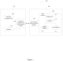
- FIG. 1 A block diagram of a functionally expandable ultrasonic imaging system is shown in FIG. 1 .
- the present embodiment provides an functionally expandable ultrasonic imaging system.
- the system 100 comprises an integrated imaging device 101 and a host machine 105.
- said integrated imaging device 101 has a complete hardware system that can independently run the configured ultrasound imaging functions, and mainly comprises an ultrasonic imaging device 102, an integrator 103, and an integrated imaging device communication interface 104; and that the host machine 105 is a part of an existing ultrasonic imaging device, mainly comprising a user terminal 109 and a host machine communication interface 110.
- the integrated imaging device 101 and the host machine 105 are identified and compared in function by the integrator 103, and based on the comparison results, operating parameters and modes of the integrated imaging device and the host machine are configured.
- the ultrasound data obtained from the scanning of the ultrasonic imaging device 102 is transmitted to a user terminal for display through the integrated imaging device communication interface and the host machine communication interface.
- the user can operate the integrated imaging device through the user terminal.
- the integrated imaging device 101 becomes an external device of the computer within the host machine 105.
- the user terminal 109 of the host machine 105 becomes a terminal device of the integrated imaging device 101.
- said ultrasonic imaging device 102 comprises an ultrasound transducer, a control unit, a processing unit and a storage unit for performing an ultrasound scan of an object under test and generating ultrasound data of the object under test for carrying out a specific imaging application.
- a one-dimensional ultrasound image e.g., an A-image and an M-image
- a two-dimensional ultrasound image e.g., a B-image, a Doppler image, an elasticity image
- a three-dimensional ultrasound image e.g., a four-dimensional ultrasound image.
- the ultrasound transducer comprises a single transducer array element arranged in points or by several transducer array elements arranged in a line array, a convex array, or a two-dimensional matrix for emitting ultrasound waves to the object under test and receiving an echo signal.
- Non-limiting transducer elements include piezoelectric elements, MEMS elements, or other transducer elements.
- a control unit is used to coordinate the functions of the units or components for executing commands to control probe operation.
- the processing unit is used to process ultrasound data to construct an ultrasound image, including an A-mode image, an M-mode image, a B-mode image, a Doppler image, an elastic image, a three-dimensional image, or a four-dimensional image.
- the storage unit is based on at least one of the hardware or the software and contains executable program code driving the integrated imaging device 101 for caching and packaging the data.
- Said data is data related to ultrasound and/or other information including, but not limited to: imaging data, transducer configuration data, other transducer data, a user database from a host machine and a patient database.
- the processing unit and the storage unit may be built into the integrated imaging device 101.
- the setup of the processing unit and the storage unit is not limited to the integrated imaging device 101, but may also be set up in the host machine 105 (described below).
- the processing unit and the storage unit are at least part of the host machine 105 and all or part of their functions are performed by the host machine 105.
- said integrated imaging device 101 is based on the ultrasonic imaging device 102 and uses other imaging means or sets up other sensors and components to realize specific functions.
- said integrated imaging device 101 is application-specific for carrying out at least one of a one-dimensional imaging application, a two-dimensional imaging application, a three-dimensional imaging application, and a four-dimensional imaging, elastography, elastometry, viscoelasticity imaging, hemodynamic imaging, acoustic attenuation imaging, and ultrahigh-speed ultrasound imaging application; it may be a low-frequency vibration-based transient elasticity measurement device (with elasticity measurement function), an ultrasound imprinting elasticity measurement device (with elasticity measurement capabilities), shear wave elasticity imaging device based on acoustic radiation force pulses (with elasticity imaging and measurement capabilities), strain elasticity imaging device based on quasi-static forces (with elasticity imaging and measurement capabilities), spatial transducer-based three-dimensional ultrasonic imaging device (with three-dimensional imaging capabilities), and transcranial ultrasound Dopp
- the integrator 103 is used to integrate the integrated imaging device 101 into the host machine 105 at the software level, and does not involve integration at the hardware circuit level, allowing said integrated imaging device 101 to be used with any host machine. It should be understood that if the integrator 103 is not working, the integrated imaging device 101 can only be used with a host machine 105 that supports the function or application of the integrated imaging device 101.
- the integrator 103 has the following functions: 1) identifying the functions of the integrated imaging device 101 and the functions supported/compatible by the host machine 105 and comparing them; 2) based on the comparison results of the functions of the integrated imaging device 101 and the host machine 105, configuring the operating parameters and modes within the integrated imaging device 101 that satisfy the requirements for operating on the host machine 105; 3) based on the pairing results of the integrated imaging device 101 and the host machine 105, if the host machine 105 does not support/is not compatible with the functions of said integrated imaging device 101, configuring the operating parameters and modes within the host machine 105 that satisfy working on the integrated imaging device 101 by importing the packaged executable program code (including the front-end user interface code and the back-end processing algorithm) into the host machine 105, so as to realize the integrated imaging device 101 to be integrated with the host machine 105 at a software level.
- the packaged executable program code including the front-end user interface code and the back-end processing algorithm
- the application modes include, but are not limited to: a one-dimensional application, a two-dimensional application, a three-dimensional application, and a four-dimensional application, etc.; and the operation modes include, but are not limited to: an ultrasonography mode, an elasticity measurement mode, an elasticity imaging mode, a viscoelasticity imaging mode, an acoustic attenuation imaging, an ultrahigh-speed ultrasound imaging, a blood flow measurement mode, a vascular imaging mode, a gastrointestinal tract imaging mode, a spine three-dimensional reconstruction mode, and a muscle three-dimensional reconstruction mode, Vascular Reconstruction Mode.
- the specific modes depend on the functions and applications supported by the integrated imaging device and are not limited by the present application.
- the integrated imaging device communication interface 104 is constructed on the integrated imaging device 101 for communicatively connecting with the host machine 105 to realize bidirectional data transmission between the integrated imaging device 101 and the host machine 105.
- the communication connection includes a wireless connection and a wired connection.
- the wired communication protocols include, but are not limited to: universal serial bus (USB), serial peripheral interface (SPI), Thunderbolt, PCIe, integrated circuit bus (I2C).
- Wireless communication protocols include, but are not limited to: WiFi, Bluetooth, Ultra-Wide Bandwidth (UWB), ZigBee, Radio Frequency Identification (RFID), Near Field Communication (NFC), 4G technology, or 5G technology. It should be appreciated by those skilled in the art that said integrated imaging device communication interface 104 is constructed to have a single or multiple communication interfaces for communicating and connecting with a host machine 105 that supports different communication protocols and interface types.
- said host machine 105 comprises a user terminal 109 and a host machine communication interface 110.
- Said user terminal 109 is at least a part of the host machine 105 that has been configured with a computer for at least one of displaying ultrasound images, displaying ultrasound-related data, controlling the operation of the integrated imaging device, and managing the database and post-processing data.
- said user terminal 109 comprises a display unit 111, a patient database 112, a user database 113 and a computer 114.
- the user terminal 109 is used only for displaying ultrasound data in picture and/or video format, but is not related to data processing.
- Said user terminal 109 is using the existing display unit 111 on the host machine as the terminal platform for interacting with the user without any changes to the host machine at the hardware level, and belongs to one of the parts of the firmware of the computer within the host machine.
- Said display unit 111 may be an external display device or a cathode ray tube display or an LCD screen embedded in the ultrasonic imaging device for displaying ultrasound images, measurements and/or ultrasound data obtained by the integrated imaging device. The form of the display depends on the existing setup of the host machine. Secondly, as far as the operation control function is concerned, when the integrated imaging device 101 is integrated into the host machine 105 at the software level, the user terminal 109 is used to host packaged executable program code (including front-end user interface code and back-end processing algorithms).
- the user interface and processing algorithms are constructed to be compatible with said host machine 105.
- the form of user interaction depends on the existing setup of the host machine.
- the user has access to the patient database 112 and the user database 113 of said integrated imaging device 101 under the current application.
- the computer 114 within said host machine stores various algorithms for accomplishing all or part of the work of the processing unit 106 within the integrated imaging device 101. This approach saves resources and arithmetic power of the integrated imaging device 101.
- the user terminal 109 is involved in signal processing, image processing, image reconstruction or multidimensional display, which may be applicable to the following three situations: 1) complete processing of data that has not been processed by the integrated imaging device 101; 2) further processing of data that has been pre-processed by the integrated imaging device 101; and 3) post-processing of data that has been processed by the integrated imaging device 101.
- said host machine communication interface 110 is at least a portion of the host machine 105 that has been configured with a computer, and belongs to a generic computer interface within the host machine 105. Said host machine communication interface 110 is constructed on a computer of the host machine 105 for communicating and connecting with the integrated imaging device 101 to realize bi-directional data transfer between the integrated imaging device 101 and the host machine 105. It is noted that the successful pairing of the integrated imaging device 101 with the host machine 105 depends on the type of interface of the existing host machine communication interface 110. Preferably, said host machine communication interface 110 is existing and does not require any changes to the host machine and is part of the firmware of one of the computers within the host machine.
- the integrated imaging device communication interface 104 is physically incompatible with the host machine communication interface 110, only a suitable adapter for the host machine communication interface 110 needs to be configured, and a communication connection can be established by making minor changes at the hardware level.
- a USB-WiFi adapter on the USB interface may enable the host machine to realize a paired connection with an integrated imaging device that supports the WiFi communication protocol.
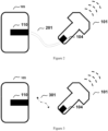
- FIG. 2 is a schematic diagram of a three-dimensional structure of a system based on a wired communication protocol provided in the first embodiment of the present application.
- a pluggable cable connection 201 is used between the integrated imaging device communication interface 104 and the host machine communication interface 110.
- Data transmission between the integrated imaging device 101 and the host machine 105 is via a wired communication protocol.
- the wired communication protocols include, but are not limited to: universal serial bus (USB), serial peripheral interface (SPI), Thunderbolt, PCIe, integrated circuit bus (I2C).
- USB universal serial bus
- SPI serial peripheral interface
- Thunderbolt Thunderbolt
- PCIe integrated circuit bus
- I2C integrated circuit bus
- FIG. 3 is a schematic diagram of a three-dimensional structure of a system based on a wireless communication protocol provided in the second embodiment of the present application.
- the present embodiment provides a system that differs from the first embodiment in that a wireless connection 301 is used between the integrated imaging device communication interface 104 and the host machine communication interface 110, as shown in FIG. 3 .
- the data transmission between the integrated imaging device 101 and the host machine 105 is performed via a wireless communication protocol.
- the wireless communication protocols include, but are not limited to, WiFi, Bluetooth, Ultra-Wide Bandwidth (UWB), ZigBee, Radio Frequency Identification (RFID), Near Field Communication (NFC), 4G technology, or 5G technology.
- the integrated imaging device is integrated at the software level into existing ultrasonic imaging devices as a sub-function to be used with existing devices that are otherwise incompatible or do not support the specific application.
- FIG. 4 A block schematic diagram of a functionally expandable ultrasonic imaging system provided in the third embodiment is shown in FIG. 4 .
- the present embodiment provides a system that differs from the first embodiment in that further, the integrated imaging device 101 further comprises a power supply unit 401.
- Said power supply unit 401 contains a battery and associated circuitry for independently supplying power to the integrated imaging device 101.
- the charging method may be wireless charging or wired charging.
- the integrated imaging device 101 does not need to rely on the host machine 105 to provide power, which is particularly suitable for the case of wireless connection.
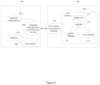
- FIG. 5 A block schematic diagram of a functionally expandable ultrasonic imaging system provided in the fourth embodiment is shown in FIG. 5 .
- the present embodiment provides a system that differs from the first embodiment in that further, the integrated imaging device 101 further comprises a user interface 501.
- Said user interface 501 is a hardware device that is physically disposed at any location of the integrated imaging device 101 for receiving commands entered by the user at the integrated imaging device side and based on the content of the commands in order to facilitate the pairing and integration of the integrated imaging device 101 and the host machine 105.
- Said commands include, but are not limited to, selection of an operation mode, selection of an application mode, adjustment of image parameters, and the like.
- the user input includes, but is not limited to: audio input, key manual input, touchpad manual input, touchscreen manual input.
- the user interface 501 is used to realize part of the functions of the user terminal in the host machine, including displaying an ultrasound image (said user interface 501 is used to complete part of the work of the display unit 111), displaying ultrasound-related data (said user interface 501 is used to complete part of the work of the display unit 111), controlling the operation of the integrated imaging device (said user interface 501 is used to complete part of the work of the display unit 111 and the computer 114) and managing a database (said user interface 501 is used to complete part of the work of the patient database 112 and/or the user database 113).
- FIG. 6 A block schematic diagram of a functionally expandable ultrasonic imaging system provided in the fifth embodiment is shown in FIG. 6 .
- the present embodiment provides a system that differs from the first embodiment in that further, the integrated imaging device 101 further comprises a sensor 601.
- Said sensor 601 may be at least one of a temperature sensor, a force sensor, a motion sensor, a three-dimensional spatial sensor, or a camera for sensing operational state information of the integrated imaging device 101 and based on the operational state information in order to facilitate the integrated imaging device 101 and the host machine 105 to pair and integrate.
- the host machine 105 may analyze and pre-determine the application mode of said to-be-connected integrated imaging device 101 based on the data changes and operation information obtained by said three-dimensional spatial sensor 601; if the integrated imaging device 101 has an application of blood flow imaging, the host machine 105 may analyze and pre-determine the application mode of said to-be-connected integrated imaging device 101 based on the data changes and operation information obtained by said motion or force sensor 601.
- the host machine 105 may analyze and predetermine the application mode of said to-be-connected integrated imaging device 101 based on the ultrasound image characteristics acquired by said integrated imaging device 101 combined with the operation information acquired by the force sensor 601.
- the operational status information sensed by the sensors may further facilitate the integration of the integrated imaging device and the host machine, thereby improving the pairing efficiency.
- FIG. 7 A block schematic diagram of a functionally expandable ultrasonic imaging system provided in the sixth embodiment is shown in FIG. 7 .
- the present embodiment provides a system that differs from the first embodiment in that the integrated imaging device 101 is not based on ultrasound imaging or the integrated imaging device 101 is not an application-specific ultrasound integrated imaging device, but is based on other biomedical imaging means such as photoacoustic imaging or thermoacoustic imaging.
- Said integrated imaging device 101 based on the photoacoustic imaging comprises a photoacoustic imaging device 701 for irradiating a pulsed laser to a subject and subsequently capturing the ultrasound signal generated by the light excitation of the tissue to generate a photoacoustic image.
- said integrated imaging device 101 based on thermoacoustic imaging is used to irradiate a pulsed laser at a radio frequency to an object under test, and subsequently acquire ultrasound signals generated by light excitation of the tissue to generate a thermoacoustic image.
- Biomedical imaging means based on photoacoustic imaging or thermoacoustic imaging are developing rapidly, and the present application can integrate photoacoustic imaging and thermoacoustic imaging into an existing host by means of the integrated imaging device based on photoacoustic imaging or the integrated imaging device based on thermoacoustic imaging, thereby expanding the scope of use of photoacoustic and thermoacoustic imaging.
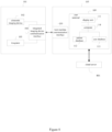
- FIG. 8 A block schematic diagram of a functionally expandable ultrasonic imaging system provided in the seventh embodiment is shown in FIG. 8 .
- the present embodiment provides a system that differs from the first embodiment in that further, the system 100 further comprises a cloud server 801.
- Said cloud server 801 is used to implement all or part of the functions of the user terminal 109 of the host machine 105 on the cloud.
- Said cloud server 801 is directly wirelessly connected to said host machine 105.
- the system 100 is connected to the cloud server 801 via the host machine 105 by wired or wireless transmission and interoperates with the data. Specifically, the system 100 uploads the relevant data obtained by said integrated imaging device 101 to said cloud server 801 and similar processing modules via the user terminal 109; said cloud server 801 performs cloud computing on the data for analysis and processing. After analyzing, computing and processing in the cloud, the processed relevant data is transmitted back to the user terminal 109 for display.
- said cloud server 801 stores various algorithms and has a data processing function for realizing signal processing, image processing, image reconstruction or multidimensional display, which can be applied to the following three situations: 1) doing complete processing to the data that has not been processed by the local system 100; 1) doing further processing to the data that has been pre-processed by the local system 100; and 2) doing post-processing to the data that has already been processed by the local system 100.
- a big data workstation may also be built on the cloud server for participating in data storage, management, retrospective analysis and sharing.
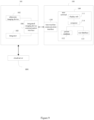
- FIG. 9 A block schematic diagram of a functionally expandable ultrasonic imaging system provided in the eighth embodiment is shown in Figure 9 .
- the present embodiment provides a system that differs from the eighth embodiment in that said cloud server 801 is wirelessly connected directly to said integrated imaging device 101 without going through a host machine.
- the system 100 is connected to the cloud server 801 via the integrated imaging device 101 by wired or wireless transmission and interoperates with the data.
- the integrated imaging device 101 uploads relevant data obtained to said cloud server 801 and similar processing modules; said cloud server 801 performs cloud computing on the data for analysis and processing.
- the processed relevant data is transmitted back to the integrated imaging device, which is then transmitted by the communication interface of the integrated imaging device to the user terminal of the host machine for display.
- this method does not require a host machine to participate in data processing, and has the following advantages: 1) saves the resources and arithmetic power of the local system; 2) promotes the miniaturization, integration, and portability of the hardware of the integrated imaging device; 3) facilitates the management of data; and 4) facilitates the updating, optimization, and execution of the more advanced AI-related algorithms.
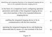
- the ninth embodiment provides a method for expanding the function of an ultrasonic imaging device, comprising the steps of:
- the configuration process includes: identifying the type and/or supported communication protocol of the integrated imaging device communication interface of said integrated imaging device, identifying the type and/or supported communication protocol of host machine communication interface of said host machine, setting the integrated imaging device to a standby connection state, importing packaged executable program code to the host machine for operation of the integrated imaging device (if required), setting the host to a pending connection state.
- said integrated imaging device communication interface and said host machine communication interface are constructed on the integrated imaging device and the host machine, respectively, for accomplishing a communication connection between the integrated imaging device and the host machine to realize a bi-directional data transmission.
- the means of communication connection includes a wireless connection and a wired connection.
- said host machine communication interface is at least a portion of a host machine that has been configured with a computer, and belongs to a generic computer interface within the host machine.
- said integrated imaging device becomes an external device of the computer in the host machine.
- a user terminal of the host machine becomes a terminal device of the integrated imaging device for displaying ultrasound images, displaying ultrasound-related data, controlling the operation of the integrated imaging device, managing the database, and post-processing data.
- step S4 comprises:
- step S4 comprises:
- the present application may also be implemented by means of a computer program product, the program containing all the features capable of implementing the methods of the present application when installed in a computer system.
- a computer program in this document refers to: any expression for a set of instructions that can be written in any programming language, code or symbol, which gives the system an information processing capability to implement a specific function directly, or to implement a specific function after one or both of the following steps have been performed: a) converted into other languages, codes or symbols; and b) reproduced in a different format.
Landscapes
- Health & Medical Sciences (AREA)
- Life Sciences & Earth Sciences (AREA)
- Engineering & Computer Science (AREA)
- Medical Informatics (AREA)
- Surgery (AREA)
- Pathology (AREA)
- Radiology & Medical Imaging (AREA)
- Biophysics (AREA)
- Biomedical Technology (AREA)
- Heart & Thoracic Surgery (AREA)
- Physics & Mathematics (AREA)
- Molecular Biology (AREA)
- Nuclear Medicine, Radiotherapy & Molecular Imaging (AREA)
- Animal Behavior & Ethology (AREA)
- General Health & Medical Sciences (AREA)
- Public Health (AREA)
- Veterinary Medicine (AREA)
- Human Computer Interaction (AREA)
- Computer Vision & Pattern Recognition (AREA)
- Computer Networks & Wireless Communication (AREA)
- Ultra Sonic Daignosis Equipment (AREA)
Applications Claiming Priority (2)
| Application Number | Priority Date | Filing Date | Title |
|---|---|---|---|
| CN202210203574.3A CN114533119B (zh) | 2022-03-03 | 2022-03-03 | 拓展超声成像设备的功能的方法和系统 |
| PCT/CN2022/121032 WO2023165119A1 (zh) | 2022-03-03 | 2022-09-23 | 拓展超声成像设备的功能的方法和系统 |
Publications (2)
| Publication Number | Publication Date |
|---|---|
| EP4487783A1 true EP4487783A1 (de) | 2025-01-08 |
| EP4487783A4 EP4487783A4 (de) | 2026-01-21 |
Family
ID=81662382
Family Applications (1)
| Application Number | Title | Priority Date | Filing Date |
|---|---|---|---|
| EP22929549.8A Pending EP4487783A4 (de) | 2022-03-03 | 2022-09-23 | Verfahren und system zur funktionserweiterung einer ultraschallbildgebungsvorrichtung |
Country Status (4)
| Country | Link |
|---|---|
| US (1) | US20240115245A1 (de) |
| EP (1) | EP4487783A4 (de) |
| CN (1) | CN114533119B (de) |
| WO (1) | WO2023165119A1 (de) |
Families Citing this family (1)
| Publication number | Priority date | Publication date | Assignee | Title |
|---|---|---|---|---|
| CN114533119B (zh) * | 2022-03-03 | 2024-12-31 | 意领科技有限公司 | 拓展超声成像设备的功能的方法和系统 |
Family Cites Families (26)
| Publication number | Priority date | Publication date | Assignee | Title |
|---|---|---|---|---|
| US5603323A (en) * | 1996-02-27 | 1997-02-18 | Advanced Technology Laboratories, Inc. | Medical ultrasonic diagnostic system with upgradeable transducer probes and other features |
| US6837853B2 (en) * | 2002-06-27 | 2005-01-04 | Acuson Corporation | System and method for using an ultrasound transducer with an integrated transducer information system |
| US20050113690A1 (en) * | 2003-11-25 | 2005-05-26 | Nahi Halmann | Methods and systems for providing portable device extended resources |
| JP2006055511A (ja) * | 2004-08-23 | 2006-03-02 | Aloka Co Ltd | 超音波診断装置 |
| CN101163987B (zh) * | 2005-04-18 | 2012-06-13 | 皇家飞利浦电子股份有限公司 | 由探头固件配置的超声诊断成像系统 |
| US9314225B2 (en) * | 2012-02-27 | 2016-04-19 | General Electric Company | Method and apparatus for performing ultrasound imaging |
| US20150238168A1 (en) * | 2012-09-13 | 2015-08-27 | Koninklijke Philips N.V. | Mobile 3d wireless ultrasound image acquisition device and ultrasound imaging system |
| BR112015021282B1 (pt) * | 2013-03-07 | 2022-01-25 | Koninklijke Philips N.V. | Dispositivo de captura de imagem por ultrassom, sistema de imageamento por ultrassom, kit de captura de imagens por ultrassom, e, método para especificar um estado operacional para um captura de imagem por ultrassom |
| US9763644B2 (en) * | 2015-03-27 | 2017-09-19 | Clarius Mobile Health Corp. | System and method for connecting and controlling wireless ultrasound imaging system from electronic device |
| KR102532286B1 (ko) * | 2015-10-14 | 2023-05-15 | 삼성메디슨 주식회사 | 무선 프로브, 초음파 영상 장치, 및 그 제어방법 |
| WO2018098311A1 (en) * | 2016-11-23 | 2018-05-31 | General Electric Company | Imaging protocol manager |
| CN109223030B (zh) * | 2017-07-11 | 2022-02-18 | 中慧医学成像有限公司 | 一种掌上式三维超声成像系统和方法 |
| CN107661121A (zh) * | 2017-10-23 | 2018-02-06 | 深圳开立生物医疗科技股份有限公司 | 一种超声探头自适应匹配方法及系统 |
| KR102607014B1 (ko) * | 2018-01-18 | 2023-11-29 | 삼성메디슨 주식회사 | 초음파 영상장치 및 그 제어방법 |
| KR102624614B1 (ko) * | 2018-03-21 | 2024-01-15 | 삼성메디슨 주식회사 | 초음파 진단 장치 및 그 제어 방법 |
| CN108955789A (zh) * | 2018-07-20 | 2018-12-07 | 广东万和新电气股份有限公司 | 一种超声波水流量传感器 |
| US12070354B2 (en) * | 2018-10-16 | 2024-08-27 | General Electric Company | Methods and system for detecting medical imaging scan planes using probe position feedback |
| CN111281422B (zh) * | 2018-12-06 | 2023-03-31 | 深圳迈瑞生物医疗电子股份有限公司 | 一种探头检测方法及超声成像装置、存储介质 |
| US20200315573A1 (en) * | 2019-04-02 | 2020-10-08 | Samsung Medison Co., Ltd. | Ultrasound diagnositic apparatus and control method thereof |
| CN210604516U (zh) * | 2019-07-09 | 2020-05-22 | 中国石油化工股份有限公司 | 适合于跨频段岩石物理参数的超声测量装置 |
| CN112336373A (zh) * | 2019-08-08 | 2021-02-09 | 深圳市恩普电子技术有限公司 | 一种基于移动终端的便携式超声诊断系统和方法 |
| CN211160968U (zh) * | 2019-12-09 | 2020-08-04 | 谷金凤 | 一种口腔科工具清洗装置 |
| CN110940986A (zh) * | 2019-12-25 | 2020-03-31 | 广东奥迪威传感科技股份有限公司 | 超声波探测装置和超声波探测系统 |
| CN114052780B (zh) * | 2020-10-29 | 2023-11-21 | 武汉联影医疗科技有限公司 | 超声探头的激活方法、装置、超声成像设备和介质 |
| CN113855072B (zh) * | 2021-09-28 | 2023-09-12 | 青岛海信医疗设备股份有限公司 | 超声设备及超声设备工作方法 |
| CN114533119B (zh) * | 2022-03-03 | 2024-12-31 | 意领科技有限公司 | 拓展超声成像设备的功能的方法和系统 |
-
2022
- 2022-03-03 CN CN202210203574.3A patent/CN114533119B/zh active Active
- 2022-09-23 US US18/572,162 patent/US20240115245A1/en active Pending
- 2022-09-23 EP EP22929549.8A patent/EP4487783A4/de active Pending
- 2022-09-23 WO PCT/CN2022/121032 patent/WO2023165119A1/zh not_active Ceased
Also Published As
| Publication number | Publication date |
|---|---|
| CN114533119B (zh) | 2024-12-31 |
| CN114533119A (zh) | 2022-05-27 |
| WO2023165119A1 (zh) | 2023-09-07 |
| US20240115245A1 (en) | 2024-04-11 |
| EP4487783A4 (de) | 2026-01-21 |
Similar Documents
| Publication | Publication Date | Title |
|---|---|---|
| CN103284757B (zh) | 用于执行超声成像的方法和设备 | |
| KR101747305B1 (ko) | 초음파 진단 장치 및 그에 따른 통신 연결 방법 | |
| KR102917269B1 (ko) | 초음파 진단장치 및 그에 따른 초음파 진단 방법 | |
| CN103228220A (zh) | 便携式超声波诊断装置 | |
| EP2829234A2 (de) | Ultraschallvorrichtung und Verfahren zur Erzeugung eines Ultraschallbildes | |
| EP3071113B1 (de) | Verfahren und vorrichtung zum anzeigen von ultraschalbildern | |
| EP4487783A1 (de) | Verfahren und system zur funktionserweiterung einer ultraschallbildgebungsvorrichtung | |
| KR20140062252A (ko) | 스마트폰을 이용한 3차원 초음파 이미지 생성방법 | |
| US11730449B2 (en) | Ultrasonic diagnostic system | |
| US10390800B2 (en) | Ultrasound diagnosis method and ultrasound diagnosis apparatus | |
| US12446864B2 (en) | Ultrasound diagnostic apparatus and method for controlling the same | |
| HK40074951A (zh) | 拓展超声成像设备的功能的方法和系统 | |
| HK40074951B (zh) | 拓展超声成像设备的功能的方法和系统 | |
| CN112336373A (zh) | 一种基于移动终端的便携式超声诊断系统和方法 | |
| CN118642088A (zh) | 用于对无线超声探头进行保持和充电的装置和超声成像系统 | |
| US11832990B2 (en) | Ultrasonic diagnostic apparatus, and medical data processing apparatus | |
| CN111031923A (zh) | 超声诊断仪及使用超声诊断仪获取远程辅助数据的方法 | |
| CN221980779U (zh) | 一种超声医学成像装置 | |
| KR102226214B1 (ko) | 스마트 장치, 프로브 장치, 그에 따른 스마트 장치 제어 방법, 및 그에 다른 프로브 장치 제어 방법, 및 그를 기록한 기록 기록 매체 | |
| JP7293737B2 (ja) | 超音波探触子、端末装置、超音波診断装置及び超音波診断システム | |
| CN121726014A (zh) | 远程访问超声成像设备的方法 | |
| CN110313942A (zh) | 图像重建方法、装置及存储介质 |
Legal Events
| Date | Code | Title | Description |
|---|---|---|---|
| STAA | Information on the status of an ep patent application or granted ep patent |
Free format text: STATUS: THE INTERNATIONAL PUBLICATION HAS BEEN MADE |
|
| PUAI | Public reference made under article 153(3) epc to a published international application that has entered the european phase |
Free format text: ORIGINAL CODE: 0009012 |
|
| STAA | Information on the status of an ep patent application or granted ep patent |
Free format text: STATUS: REQUEST FOR EXAMINATION WAS MADE |
|
| 17P | Request for examination filed |
Effective date: 20240209 |
|
| AK | Designated contracting states |
Kind code of ref document: A1 Designated state(s): AL AT BE BG CH CY CZ DE DK EE ES FI FR GB GR HR HU IE IS IT LI LT LU LV MC MK MT NL NO PL PT RO RS SE SI SK SM TR |
|
| DAV | Request for validation of the european patent (deleted) | ||
| DAX | Request for extension of the european patent (deleted) | ||
| A4 | Supplementary search report drawn up and despatched |
Effective date: 20251218 |
|
| RIC1 | Information provided on ipc code assigned before grant |
Ipc: A61B 8/00 20060101AFI20251212BHEP |