EP4487784A1 - Dispositif à ultrasons pour mesurer un flux sanguin dans un vaisseau sanguin - Google Patents
Dispositif à ultrasons pour mesurer un flux sanguin dans un vaisseau sanguin Download PDFInfo
- Publication number
- EP4487784A1 EP4487784A1 EP23183627.1A EP23183627A EP4487784A1 EP 4487784 A1 EP4487784 A1 EP 4487784A1 EP 23183627 A EP23183627 A EP 23183627A EP 4487784 A1 EP4487784 A1 EP 4487784A1
- Authority
- EP
- European Patent Office
- Prior art keywords
- piezoceramics
- housing
- measurement
- piezoceramic
- blood flow
- Prior art date
- Legal status (The legal status is an assumption and is not a legal conclusion. Google has not performed a legal analysis and makes no representation as to the accuracy of the status listed.)
- Granted
Links
Images




Classifications
-
- A—HUMAN NECESSITIES
- A61—MEDICAL OR VETERINARY SCIENCE; HYGIENE
- A61B—DIAGNOSIS; SURGERY; IDENTIFICATION
- A61B8/00—Diagnosis using ultrasonic, sonic or infrasonic waves
- A61B8/06—Measuring blood flow
-
- A—HUMAN NECESSITIES
- A61—MEDICAL OR VETERINARY SCIENCE; HYGIENE
- A61B—DIAGNOSIS; SURGERY; IDENTIFICATION
- A61B8/00—Diagnosis using ultrasonic, sonic or infrasonic waves
- A61B8/08—Clinical applications
- A61B8/0891—Clinical applications for diagnosis of blood vessels
-
- A—HUMAN NECESSITIES
- A61—MEDICAL OR VETERINARY SCIENCE; HYGIENE
- A61B—DIAGNOSIS; SURGERY; IDENTIFICATION
- A61B8/00—Diagnosis using ultrasonic, sonic or infrasonic waves
- A61B8/42—Details of probe positioning or probe attachment to the patient
- A61B8/4209—Details of probe positioning or probe attachment to the patient by using holders, e.g. positioning frames
- A61B8/4227—Details of probe positioning or probe attachment to the patient by using holders, e.g. positioning frames characterised by straps, belts, cuffs or braces
-
- A—HUMAN NECESSITIES
- A61—MEDICAL OR VETERINARY SCIENCE; HYGIENE
- A61B—DIAGNOSIS; SURGERY; IDENTIFICATION
- A61B8/00—Diagnosis using ultrasonic, sonic or infrasonic waves
- A61B8/44—Constructional features of the ultrasonic, sonic or infrasonic diagnostic device
- A61B8/4483—Constructional features of the ultrasonic, sonic or infrasonic diagnostic device characterised by features of the ultrasound transducer
-
- A—HUMAN NECESSITIES
- A61—MEDICAL OR VETERINARY SCIENCE; HYGIENE
- A61B—DIAGNOSIS; SURGERY; IDENTIFICATION
- A61B8/00—Diagnosis using ultrasonic, sonic or infrasonic waves
- A61B8/48—Diagnostic techniques
- A61B8/488—Diagnostic techniques involving Doppler signals
-
- A—HUMAN NECESSITIES
- A61—MEDICAL OR VETERINARY SCIENCE; HYGIENE
- A61B—DIAGNOSIS; SURGERY; IDENTIFICATION
- A61B8/00—Diagnosis using ultrasonic, sonic or infrasonic waves
- A61B8/52—Devices using data or image processing specially adapted for diagnosis using ultrasonic, sonic or infrasonic waves
- A61B8/5215—Devices using data or image processing specially adapted for diagnosis using ultrasonic, sonic or infrasonic waves involving processing of medical diagnostic data
- A61B8/5223—Devices using data or image processing specially adapted for diagnosis using ultrasonic, sonic or infrasonic waves involving processing of medical diagnostic data for extracting a diagnostic or physiological parameter from medical diagnostic data
Definitions
- the invention relates to an ultrasound device for measuring fluid flows, in particular for measuring the blood flow in a blood vessel.
- the ultrasound device has a measuring electronics, at least three piezoceramics and a housing.
- each piezoceramic is arranged in the housing at a different angle to the sound exit surface of the housing.
- the housing has at least one means for fastening the housing to a patient or an aid.
- the arterial blood flow through the carotid artery can serve as a representative value for assessing the effectiveness of resuscitation measures.
- the state of the art in assessing cardiac massage is still the frequency and depth of compression.
- the actual blood flow caused and the associated oxygen supply to the brain are not known to the rescuer or the medical staff.
- animal experiments have already shown that survival from cardiac arrest is directly dependent on cerebral blood flow during resuscitation measures [1]. It is not uncommon for patients to survive the resuscitation event but still not recover due to a poor neurological prognosis. Even if spontaneous circulation is achieved, the neurological outcome of the patient is directly dependent on the quality of the resuscitation and the minimization of the "no-flow" periods in which no oxygen-rich blood is transported to the brain.
- Doppler sonography uses the measured frequency differences between transmitted and received ultrasound signals caused by the Doppler effect to detect moving matter.
- the ultrasound waves reflected by red blood cells can thus be used to measure the speed of blood flow during resuscitation.
- Doppler sonographic measurement of the arterial blood flow in the common carotid artery is already possible during resuscitation, but devices for stationary use are not practical for this application.
- the ultrasound heads and computers used for measurement/analysis are too large and are dependent on a power supply from the mains.
- the ultrasound heads require manual operation; long-term, permanent attachment to the person, where no one has to hold the measuring device, is effectively not possible.
- the device also lacks additional fastenings and a compactness that would allow the ultrasound head to be attached quickly, easily and robustly over an artery without compromising it.
- the interpretation of the results of B-image and Doppler sonography also requires a certain level of expertise that is not widely available in the emergency services. An automated evaluation of the hemodynamic parameters would therefore be necessary here. This in turn requires additional signal processing steps to compensate for artifacts caused by movements of the body and the ultrasound transducers.
- the L7 Linear Handheld Ultrasound Scanner from Clarius (Vancouver, CA) is one such device, which uses several integrated ultrasound transducers to record tissue structures and emerging movements.
- the measurement method which uses continuous wave Doppler with a transmitter and a receiver, has the advantage of covering a large area through which the ultrasound is transmitted, but it also detects a large number of interference signals (e.g. tissue movements), the filtering of which can affect the quality of the blood flow signal.
- interference signals e.g. tissue movements
- This disadvantage is exacerbated by the movement artifacts that occur during resuscitation, as can be seen in the color Doppler images taken during resuscitation by Koch et al. [3].
- quantitative position and orientation detection of the carotid artery using only one receiving probe is not practical, so that an accurate determination of the quantitative blood flow is difficult to achieve.
- the limited flexibility in the attachment of the desired system has a major disadvantage, as no corrections can be made to the measurement position during resuscitation.
- the area on the neck that is being used cannot be quickly freed from the measurement technology in order to to be able to reattach them quickly and easily after repositioning, invasive access or other activities.
- the devices are dependent on external systems and do not allow direct information to be sent to the user.
- the WO 2017/096487 discloses a portable monitoring device that operates exclusively with transducer pairs.
- the invention provides an ultrasound device according to claims 1 to 8 and a method according to claims 9 to 11.
- the ultrasound device according to the invention is used to measure a blood flow in a blood vessel.
- the ultrasound device has a measuring electronics, at least three piezoceramics and a housing. According to the invention, the at least three piezoceramics are arranged in the housing.
- the housing has exactly three piezoceramics.
- each piezoceramic in the housing is arranged at a different angle to the sound exit surface of the housing.
- the angle of the normal of the piezoceramic to the normal of the sound exit surface is considered.
- the housing wall through which the sound waves generated by the piezoceramics exit towards the body tissue and through which the reflected ultrasonic waves enter the housing is referred to as the sound exit surface.
- the piezoceramics can be arranged at an angle between 90° and 0°, preferably between 75° and 0°, to the sound exit surface of the housing.
- the angles of the piezoceramics differ between ⁇ 5° and ⁇ 30°, preferably between ⁇ 10° and ⁇ 25°.
- the piezoceramics are mounted on a coupling path in the housing.
- the coupling path preferably consists of biocompatible materials with low damping and good impedance matching to the piezoceramics and the skin. Due to the design of the housing, the positions and thus the angles of the piezoceramics in the housing are known.
- any conventional ceramic that can be used in the ultrasound range can be used as a piezoceramic.
- a composite ceramic is preferably used.
- the geometry of the piezoceramic is selected so that an essentially homogeneous sound field is generated.
- the piezoceramic preferably has a rectangular or elliptical cross-section.
- the size of the piezoceramics is selected so that they can fit in the housing and the sound exit surface of the housing can be placed over the entire surface of a patient's neck.
- all piezoceramics are designed to emit continuous wave Doppler ultrasound signals (cw) and/or pulsed Doppler ultrasound signals (burst).
- the device according to the invention is designed to work in at least three modes, whereby a mode designates a specific measurement sequence.
- a mode designates a specific measurement sequence.
- different piezoceramics are provided for the transmission and/or reception of ultrasonic signals.
- the first mode which is referred to below as mode 0, was used to assess the correct position and coupling of the ultrasound device according to the invention to a patient.
- mode 0 one piezoceramic works as a transmitter while all available piezoceramics work as receivers. If pulse Doppler signals are sent, all piezoceramics, including the transmitting ceramic, work as receivers.
- a second mode referred to as mode 1 below, is used to determine the vessel depth, the vessel diameter and the Doppler angle of the piezoceramics.
- mode 1 all piezoceramics are used as transmitters one after the other, while all available piezoceramics receive the reflected ultrasound signal simultaneously. If pulse Doppler signals are sent, all piezoceramics, including the transmitting ceramic, work as receivers.
- a third mode is used for quantified blood flow measurement.
- a piezoceramic serves as a transmitter while all available piezoceramics simultaneously serve as receivers. If pulse Doppler signals are used, all piezoceramics, including the transmitting ceramic, work as receivers.
- the ultrasound device is set up to measure in at least 3 modes, with a piezoceramic working as a transmitter in all modes and all available piezoceramics working as receivers, with all available piezoceramics working as receivers working as receivers in at least two modes.
- simultaneous means that the respective piezoceramics measure the ultrasonic signal received at the piezoceramics at exactly the same time.
- the Doppler angle describes the angle between the sound path and the flow direction of the blood stream in the blood vessel.
- the angles of the piezoceramics to the sound exit surface are known from the design of the ultrasound device.
- the ultrasound device also has appropriate measuring electronics to control the piezoceramics.
- the measuring electronics are responsible for energy regulation, measurement data acquisition, demodulation, sound and evaluation of the Doppler signals.
- the measuring electronics transmit electrical energy to the piezoceramics to generate ultrasound.
- the housing also has a circuit board from which a multi-pole cable connection goes to the measuring electronics.
- the circuit board is also connected to the piezoceramics and is responsible for amplifying and demodulating transmitted and measured signals.
- the measuring electronics and the circuit board are designed to activate separate but also synchronized transmission and reception periods for each piezoceramic.
- the measuring electronics also have a data storage device.
- the measurement signals from the ultrasound device can be stored in the data storage device. This makes it possible to subsequently evaluate the measurement data during an animation process and, for example, to store it in an electronic patient file.
- the measuring electronics therefore also have an output for a connection to a network, for example via WLAN, Bluetooth or cable, and/or an output for an external storage medium, for example a USB port. Stored data can be read out via this output or these outputs.
- the measuring electronics are arranged in the same housing as the at least three piezoceramics. In a further embodiment, the measuring electronics are arranged in a further housing at a distance from the housing with the at least three piezoceramics. In this embodiment, the ultrasound device accordingly has two housings. The housings are connected to one another by suitable cables.
- the energy supply of the ultrasound device according to the invention is preferably carried out via a suitable portable energy storage device and/or via a connection to the power grid via an adapter.
- the ultrasound emitted by the ultrasound device according to the invention is in the range of non-invasive diagnostic ultrasound.
- Non-invasive diagnostic ultrasound is defined in DIN EN 60601-2-37 (Medical Electrical Equipment Part 2-37). By definition, non-invasive ultrasound does not constitute an intervention on the body being examined.
- the housing further comprises at least one means for fastening the housing to a patient or to an aid.
- the ultrasound device is attached to the neck of a patient by the at least one means for fastening the housing.
- the ultrasound device is attached to the body in a detachable and non-invasive manner. If the ultrasound device is attached to an aid by the at least one means for fastening, the aid is in turn preferably suitable for being attached to the neck of a patient.
- the aid to which the housing can be attached with the at least one means for fastening is a Laerdal Stiffneck neck brace.
- the housing has exactly one means for attaching the housing to a patient or to an aid.
- the at least one fastening means is selected from the group comprising holders made of plastic, neck collars and cuffs, in particular neck collars and cuffs made of stretchable textile.
- the at least one fastening means can be used to fix the ultrasound device to the body, in particular to the neck of a person.
- the present invention dispenses with self-adhesive materials for attaching the ultrasound device to the body. This is particularly advantageous if the blood flow in a blood vessel on the neck of a patient is to be measured. A central point in measuring the blood flow in a blood vessel is the correct positioning of the measuring piezoceramics over the blood vessel in question.
- the ultrasound device according to the invention offers the advantage that the position of the ultrasound device can be quickly changed and adjusted if necessary. Skin irritations are This can be avoided and even if the patient has hair, it can be attached to the neck without any problems.
- the housing with the at least three piezoceramics can be attached to a Laerdal stiffneck neck brace using a plastic holder.
- the housing is arranged so that the sound outlet surface rests against the neck of a patient.
- the measuring electronics are not arranged in the housing of the at least three piezoceramics, but in another housing. This other housing can be attached to the side of the Laerdal stiffneck neck brace facing away from the patient.
- the position and pressure on the neck can be adjusted to suit the patient using manually inflatable air cushions. Activating a check valve on a pump and unlocking a locking mechanism on the neck brace guarantees that the ultrasound device can be removed easily.
- the housing of the ultrasound device therefore also has at least one inflatable air cushion.
- the position of the ultrasound device according to the invention is changed by moving the holder on the neck brace, wherein due to the contact pressure the position of the ultrasound device cannot be changed when the neck brace is closed.
- the housing with the at least three piezoceramics is fixed to the neck of a patient using a stretchable textile, a rubber band or a specially developed neck brace.
- the rubber band can, for example, be passed through the housing and run between the measuring electronics and the at least three piezoceramics and the coupling section.
- the ultrasound device is then attached to the neck in such a way that the sound outlet surface rests against the patient's neck.
- the measured signals are transmitted to an external screen.
- the ultrasound device has appropriate connections for data transmission (WLAN, Bluetooth, cable, etc.).
- the ultrasound device further comprises at least one signal generator in the form of a display and/or an acoustic signal output.
- the invention thus dispenses with the connection of third-party devices, monitors or similar. Instead of data transmission via Bluetooth or wireless LAN, measured values are immediately evaluated by the measuring electronics and used for the display.
- the display and/or the acoustic signal thus provide a direct conclusion about the blood flow in the monitored blood vessel.
- LEDs are used in one embodiment, which indicate the approximate, current Display blood flow value and/or the signal strength of the measurement signal and/or the evaluation of the approximated blood flow during the past minute(s).
- the signal generator is located on the housing of the ultrasound device and is arranged such that the signal generator is clearly visible.
- the signal generator can also be arranged on the housing which comprises the measuring electronics.
- the blood flow in a blood vessel can be measured and displayed, for example during the resuscitation of a patient.
- the signal generator is controlled by the measuring electronics in the housing.
- the ultrasound device according to the invention is attached to the skin on the neck of a patient via a holder.
- the method according to the invention can be used to obtain a reflection signal through the vessel wall and a reflection signal through scattering on the erythrocytes. This allows wall movements and movements of the erythrocytes to be detected accordingly. The movement of the erythrocytes as well as the wall movement is caused by the blood flow.
- the energy supply is interrupted when using pulsed Doppler ultrasound signals in order to receive the reflections of the emitted ultrasound waves.
- the reflected mechanical waves experience a frequency shift due to the Doppler effect.
- a measurement is first carried out with a mode 0 in which one piezoceramic works as a transmitter while all available piezoceramics work as receivers. All available piezoceramics work as receivers means that in cw mode one piezoceramic transmits while all other piezoceramics receive, and in pulse Doppler mode all piezoceramics receive, including the piezoceramic that acts as a transmitter.
- the measurement is synchronized via system-internal triggers.
- the mode is used to assess the correct position and coupling of the transducer to the system to be measured (e.g. neck).
- the piezoceramic whose angle to the sound exit surface differs the least from 90° is used as the transmitter in mode 0. If a piezoceramic is arranged at exactly an angle of 90° to the sound exit surface in the ultrasound device according to the invention, the piezoceramic whose angle to the sound exit surface differs the least from the piezoceramic with a perpendicular angle to the ultrasound exit surface is used. This results in a good compromise for the scattering signal of the blood cells (as large a Doppler angle as possible) and the reflection signal of the wall movement (as small a Doppler angle as possible).
- the gate depths for the pulse Doppler measurement are preferably chosen to be small and the gate size large. The selection of suitable parameters is familiar to the person skilled in the art.
- the gate depth is synonymous with the measurement gate depth, which is also referred to as the runtime window.
- parameter profiles for different neck proportions of a patient are additionally provided for quick adjustment of the gate, from which the user selects one that corresponds to the neck proportions of the patient.
- a measuring range between 12 mm and 30 mm depth in the patient's body tissue.
- the reflections measured by the respective piezoceramics are used to calculate spectrograms. These can be adjusted with power/intensity limits and value ranges. Based on the low-frequency power in the spectrogram, a visual-manual or automatic confirmation can be made as to whether the set Doppler gate covers a blood-perfused vessel. If coverage is successful, the spectrograms periodically contain high signal power/intensity/power in the low frequencies that arise from vessel wall movements. Stored reference values are used for an automatic assessment, with which the measurement signals are compared.
- the measured values are compared with reference values and an assessment is made as to whether a blood vessel with blood flow is detected during the measurement.
- Information is then output as to whether a blood vessel with blood flow is detected during the measurement.
- the information can be output on a connected screen and/or via LEDs and/or the output of an acoustic signal.
- the position of the ultrasound device according to the invention on the patient can be changed if no blood vessel through which blood flows is detected in the measurement.
- a measurement is also carried out in mode 1.
- each piezoceramic works as a transmitter, while all available piezoceramics work as receivers. Measurements with different gate depths are carried out with each piezoceramic. The reflected ultrasonic signals are recorded by the receivers at the same time.
- the mode is used to determine the vessel depth, the vessel diameter and the Doppler angle of each piezoceramic in the ultrasound device according to the invention.
- mode 1 all piezoceramics are used as transmitters one after the other. While one piezoceramic is transmitting, all available piezoceramics receive the Reflections and scattered signals.
- the fact that all available piezoceramics work as receivers means that in cw mode one piezoceramic transmits while all other piezoceramics receive, and in pulse Doppler mode all piezoceramics receive, including the piezoceramic that acts as a transmitter. The measurement is synchronized via system-internal triggers.
- the measurement is carried out in several measuring loops.
- the gate depth of the measurement is iteratively increased for all receiving piezoceramics.
- measurements are taken for a defined time.
- the gate size is the same for each gate depth.
- a measuring loop comprises an iteration loop over the gate depth.
- the gate size can also be changed iteratively for each gate depth.
- a measuring loop comprises two iteration loops, one over the gate size and one over the gate depth.
- a measurement with mode 1 means that measuring loops are run for all piezoceramics of the ultrasonic device.
- Each measurement within a measurement loop consists of recording the Doppler data for each piezoceramic and calculating the spectrogram, which represents the distribution of power along the frequency range.
- the received signal curves are demodulated from their carrier frequency and examined for their spectral properties using a short-time Fourier transformation, the result of which, the ratio of the signal power depending on the associated frequencies, is the spectrogram arranged along time.
- the maximum frequencies with sufficient power that the piezoceramics have received can be determined using an enveloping function.
- a piezoceramic that has a perpendicular angle to the vessel axis has no power in the higher frequency ranges that reflect blood flow, but in the low Doppler frequencies that reflect wall movements.
- the piezoceramic with the smallest angle difference of 90° to the sound exit surface can be determined if several transducers have different signal intensities above the frequency threshold along the gate displacement.
- a comparison of the low frequency signal power of this piezoceramic along the different gate depths is used to determine the vessel depth and to approximate the vessel diameter.
- the distance to the vessel can be determined for this piezoceramic.
- an envelope function of the maximum intensity is calculated along the time axis of the spectrogram. If the envelope function shows signs of periodic behavior in the desired frequency range of a person's pulse or the resuscitation rate (54 BPM - 120 BPM), this can be taken as an indication that the associated piezoceramic is highly likely to detect blood flow in the vessel.
- the vessel position and thus the exact Doppler angle can be calculated based on the rigid angular relationships between the transducers.
- Spectrogram data are then converted from frequency values to quantified velocity values by substituting the Doppler angles.
- the best parameterization with regard to transmitter-receiver settings and gate properties is determined by comparing the signal power of the enveloping functions in the blood flow frequency range (of all spectrograms from all Doppler configurations). This means that the optimal piezoceramic is determined as a transmitter and the associated optimal gate depth and, if applicable, gate length.
- the parameter set and all recorded Doppler data as well as the parameters determined from them are preferably stored in the measuring electronics.
- the vessel depth, vessel diameter and Doppler angle of the individual piezoceramics are calculated from the measurement data in mode 1.
- the vessel depth and vessel diameter are derived from the gate variation, taking into account the speed of sound and the angle of incidence to the normal.
- the Doppler angle is derived from the average frequency shifts for two piezoceramics as follows: parameter Sign volume flow V ⁇ Average velocity in the vessel v vessel diameter d ultrasonic transmission frequency f 0 speed of sound c Doppler transmission angle ⁇ SE Doppler reception angle ⁇ EM mean frequency shift ⁇ f angle of a piezoceramic to the sound exit surface ⁇
- a measurement is carried out using mode 2.
- mode 2 one piezoceramic works as a transmitter, while all available piezoceramics work as receivers.
- the reflected ultrasonic signals are recorded by the receivers at the same time.
- the fact that all available piezoceramics work as receivers means that in cw mode, one piezoceramic transmits while all other piezoceramics receive, and in pulse Doppler mode, all piezoceramics receive, including the piezoceramic that acts as a transmitter.
- the measurement is synchronized using system-internal triggers.
- a parameter set can be selected by a user or the parameter set that showed the best signal-to-noise ratio (SNR) when measuring in mode 1 is selected automatically.
- the parameter set is selected automatically.
- the configuration determines which piezoceramic sends ultrasound signals and how deep and how large the receiving gate of each piezoceramic is.
- a continuous pulse Doppler measurement with consistent settings takes place in mode 2.
- Spectrograms are calculated based on the received data.
- stored information on the Doppler angle of each piezoceramic can be used to determine flow velocities from the frequency values of the spectrograms.
- Envelope functions or flow curves are calculated from the calculated data.
- Various flow information such as average blood flow velocity, systolic peak velocity, end-diastolic peak velocity, pulse/resuscitation frequency can then be determined from the flow curves.
- the velocity of the blood flow and/or the volume flow is calculated from the measurement signals of the measurement with mode 2 and the calculated vessel depth, the vessel diameter and the Doppler angle of the piezoceramics.
- the calculated blood flow is displayed on a display on the ultrasound device.
- the determined blood flow values can be evaluated over time to determine whether the ultrasound device is well positioned over the blood vessel and whether a blood flow is generated that corresponds to previously programmed target values.
- at least one target value for the blood flow is stored in the measuring electronics.
- LEDs which are either located on the ultrasound device, show the user the extent of the blood flow generated and/or the quality of the determined signal and/or the blood flow trend of the last minute(s).
- the displays can be realized via an LED bar for the current speed, a status LED for the flow trend (e.g. red-yellow-green for 1 minute, 10 minutes, 1/2 hour) and status LEDs (e.g. red-yellow-green) for the signal/position quality.
- an acoustic signal is emitted when the calculated blood flow deviates from a target value stored in the measuring electronics.
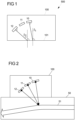
- FIG. 1 shows in a simplified manner an ultrasonic device 500 according to the invention.
- the ultrasonic device 500 has three piezoceramics 10, 11, 12.
- the piezoceramic 10 is arranged at an angle ⁇ 1 and the piezoceramic 12 at an angle ⁇ 2 in the housing 100.
- the angle is the angle between the normal of the piezoceramic and the normal of the sound exit surface 101 of the housing through which the ultrasound is emitted.
- the angle for the piezoceramic 11 is not marked.
- Figure 2 shows an ultrasound device 500 according to the invention on a blood vessel 51 in a body tissue 50.
- the three piezoceramics 10, 11, 12 are each arranged at different angles in the housing 100 and therefore radiate the ultrasound at different angles into the blood vessel 51, which lies in the body tissue 50.
- FIG. 3 represents a Laerdal-Stiffneck neck collar 70.
- An ultrasound device 500 according to the invention is attached to this.
- the ultrasound device 500 has a housing 100 in which three piezoceramics 10, 11, 12 are arranged.
- the housing 100 also has a holder 1010 with which the housing is attached to the Laerdal-Stiffneck neck collar 70.
- the ultrasound device 500 also has an air cushion 80a, the air filling of which can be regulated via the access 80b. This can be done, for example, via a syringe.
- the measuring electronics are housed in a further housing, which is attached to the side of the Laerdal-Stiffneck neck collar 70 facing away from the patient.
- the housing 100 with the piezoceramics 10, 11, 12 is connected by a cable to the further housing in which the measuring electronics are located.
- Figure 4 shows a section of a Laerdal-Stiffneck neck brace 70 with an ultrasound device 500 according to the invention.
- Figure 3 The features described above can be seen even more clearly. The description of the Figure 3 meets the same meadow Figure 4 to.
- FIG. 5 shows a section of a Laerdal-Stiffneck neck brace 70 with an ultrasound device 500 according to the invention.
- the rear of the ultrasound device 500 according to the invention can be seen.
- the holder of the ultrasound device 500 is designed such that the position of the housing 100 and thus of the piezoceramics 10, 11, 12 on the Laerdal-Stiffneck neck brace 70 can be changed.
- This allows the position of the housing 100 on the neck of a patient to be adjusted.
- the position of the housing 100 is changed using the adjusting screw 121 and the positioning strip 120. By turning the adjusting screw, the housing can be moved along the positioning strip.
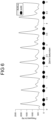
- Figure 6 symbolically represents the envelope of the intensities of a spectrogram.
- the envelope reflects the signal component caused by the blood flow in the vessel.
- the points on the time axis symbolize the signals caused by the vessel movement.
- the first point always reflects the signal caused by the vessel movement when the vessel expands and the point immediately following it reflects the signal caused by the vessel movement when the vessel contracts.
- Figure 7 (A) to (E) represent envelopes of the intensities of spectrograms recorded with a piezoceramic for different gate depths. The figures are described in more detail in Example 2.
- the ultrasound device was integrated into a Laerdal stiffneck. In this form, it can be attached to the patient after a patient without spontaneous circulation has been safely positioned.
- the measuring module was located at a point on the stiffneck that was optimal for recording blood flow in the carotid artery using Doppler sonography in several subjects. After attachment, the surface coverage of the ultrasound sensor was checked, with the ultrasound sensor coverage of the neck and the contact pressure being optimized by inflating the air cushion.
- the ultrasound device was integrated into a Laerdal stiffneck and attached to a phantom with a simulated blood flow.
- a phantom made of agar-agar gel with aluminum oxide added was used as the phantom.
- the phantom thus conducted ultrasound in accordance with the requirements of DIN IEC 60601-2-37 for tissue phantoms for testing ultrasound devices.
- a pump for generating a simulated blood flow was connected to the phantom in a closed circuit via elastic silicone tubes and nozzles. A silicone tube thus simulated a blood vessel.
- the Doppler angle can be calculated according to formulas (3) to (6).
- An ultrasound device was built with three piezoceramics.
- the piezoceramics were arranged at an angle of 0°, 10° and 25°.
- the housing of the ultrasound device also had an LED display and a flexible textile holder for fixing the device to the neck of a patient.
Landscapes
- Health & Medical Sciences (AREA)
- Life Sciences & Earth Sciences (AREA)
- Engineering & Computer Science (AREA)
- Biomedical Technology (AREA)
- Medical Informatics (AREA)
- Veterinary Medicine (AREA)
- Biophysics (AREA)
- Nuclear Medicine, Radiotherapy & Molecular Imaging (AREA)
- Pathology (AREA)
- Radiology & Medical Imaging (AREA)
- Public Health (AREA)
- Heart & Thoracic Surgery (AREA)
- Physics & Mathematics (AREA)
- Molecular Biology (AREA)
- Surgery (AREA)
- Animal Behavior & Ethology (AREA)
- General Health & Medical Sciences (AREA)
- Physiology (AREA)
- Computer Vision & Pattern Recognition (AREA)
- Vascular Medicine (AREA)
- Gynecology & Obstetrics (AREA)
- Hematology (AREA)
- Ultra Sonic Daignosis Equipment (AREA)
Priority Applications (3)
| Application Number | Priority Date | Filing Date | Title |
|---|---|---|---|
| EP23183627.1A EP4487784B1 (fr) | 2023-07-05 | 2023-07-05 | Mesurer un flux sanguin dans un vaisseau sanguin par ultrasons |
| AU2024290986A AU2024290986A1 (en) | 2023-07-05 | 2024-06-27 | Ultrasonic apparatus for measuring a blood flow in a blood vessel |
| PCT/EP2024/068150 WO2025008269A1 (fr) | 2023-07-05 | 2024-06-27 | Appareil à ultrasons pour mesurer un écoulement sanguin dans un vaisseau sanguin |
Applications Claiming Priority (1)
| Application Number | Priority Date | Filing Date | Title |
|---|---|---|---|
| EP23183627.1A EP4487784B1 (fr) | 2023-07-05 | 2023-07-05 | Mesurer un flux sanguin dans un vaisseau sanguin par ultrasons |
Publications (3)
| Publication Number | Publication Date |
|---|---|
| EP4487784A1 true EP4487784A1 (fr) | 2025-01-08 |
| EP4487784C0 EP4487784C0 (fr) | 2026-02-25 |
| EP4487784B1 EP4487784B1 (fr) | 2026-02-25 |
Family
ID=87158004
Family Applications (1)
| Application Number | Title | Priority Date | Filing Date |
|---|---|---|---|
| EP23183627.1A Active EP4487784B1 (fr) | 2023-07-05 | 2023-07-05 | Mesurer un flux sanguin dans un vaisseau sanguin par ultrasons |
Country Status (3)
| Country | Link |
|---|---|
| EP (1) | EP4487784B1 (fr) |
| AU (1) | AU2024290986A1 (fr) |
| WO (1) | WO2025008269A1 (fr) |
Citations (4)
| Publication number | Priority date | Publication date | Assignee | Title |
|---|---|---|---|---|
| US20060241460A1 (en) * | 2005-02-14 | 2006-10-26 | Fumio Kimura | Blood rheology measurement device and blood rheology measurement method |
| WO2017096487A1 (fr) | 2015-12-10 | 2017-06-15 | 1929803 Ontario Corp. D/B/A Ke2 Technologies | Systèmes et procédés pour mesure de réponse de fluide automatisée |
| EP3505071A1 (fr) * | 2017-12-28 | 2019-07-03 | Przedsiebiorstwo Wdrozeniowo-Produkcyjne Sonomed sp. z o. o. | Sonde a ultrasons pour doppler dispositif pour ondes continues (cw) et son utilisation |
| EP3823536A1 (fr) | 2018-07-17 | 2021-05-26 | 1929803 Ontario Corp. D/B/A Flosonics Medical | Patch ultrasonore pour détecter un écoulement de fluide |
Family Cites Families (1)
| Publication number | Priority date | Publication date | Assignee | Title |
|---|---|---|---|---|
| WO2007056386A2 (fr) * | 2005-11-07 | 2007-05-18 | Dvx, Llc. | Appareil a ultrasons et procede de generation de signaux audio par doppler |
-
2023
- 2023-07-05 EP EP23183627.1A patent/EP4487784B1/fr active Active
-
2024
- 2024-06-27 AU AU2024290986A patent/AU2024290986A1/en active Pending
- 2024-06-27 WO PCT/EP2024/068150 patent/WO2025008269A1/fr not_active Ceased
Patent Citations (5)
| Publication number | Priority date | Publication date | Assignee | Title |
|---|---|---|---|---|
| US20060241460A1 (en) * | 2005-02-14 | 2006-10-26 | Fumio Kimura | Blood rheology measurement device and blood rheology measurement method |
| WO2017096487A1 (fr) | 2015-12-10 | 2017-06-15 | 1929803 Ontario Corp. D/B/A Ke2 Technologies | Systèmes et procédés pour mesure de réponse de fluide automatisée |
| US20170332995A1 (en) * | 2015-12-10 | 2017-11-23 | 1929803 Ontario Corp. D/B/A Ke2 Technologies | Systems and methods for automated fluid response measurement |
| EP3505071A1 (fr) * | 2017-12-28 | 2019-07-03 | Przedsiebiorstwo Wdrozeniowo-Produkcyjne Sonomed sp. z o. o. | Sonde a ultrasons pour doppler dispositif pour ondes continues (cw) et son utilisation |
| EP3823536A1 (fr) | 2018-07-17 | 2021-05-26 | 1929803 Ontario Corp. D/B/A Flosonics Medical | Patch ultrasonore pour détecter un écoulement de fluide |
Non-Patent Citations (3)
| Title |
|---|
| A. SCHNEIDER ET AL.: "Cerebral Resuscitation After Cardiocirculatory Arrest", ANESTHESIA & ANALGESIA, vol. 108, no. 3, March 2009 (2009-03-01), pages 971 - 979 |
| M. KOCH ET AL.: "J Clin Med", vol. 11, 17 January 2022, article "Carotid Artery Ultrasound in the (peri-) Arrest Setting-A Prospective Pilot Study", pages: 469 |
| S.H. FRIESS: "Hemodynamic directed cardiopulmonary resuscitation improves short-term survival from ventricular fibrillation cardiac arrest.", CRIT CARE MED, vol. 41, 2013, pages 2698 - 704 |
Also Published As
| Publication number | Publication date |
|---|---|
| WO2025008269A1 (fr) | 2025-01-09 |
| AU2024290986A1 (en) | 2026-02-12 |
| EP4487784C0 (fr) | 2026-02-25 |
| EP4487784B1 (fr) | 2026-02-25 |
Similar Documents
| Publication | Publication Date | Title |
|---|---|---|
| DE4442260C2 (de) | Verfahren und Anordnung zur nicht invasiven in vivo Bestimmung der Sauerstoffsättigung | |
| DE69433664T2 (de) | Foetal-sensor | |
| DE68923051T2 (de) | Verfahren und vorrichtung zur bestimmung des blutdrucks und des herzzustandes. | |
| DE69419614T2 (de) | Verfahren und vorrichtung zur unblutigen ermittlung und anzeige von dynamischen parametern der menschlichen und tierischen intrakraniellen medien | |
| DE69837392T2 (de) | Verfahren und vorrichtung zur messung des intrakraniellen druckes | |
| DE69313283T2 (de) | Medizinische vorrichtung | |
| EP0467853B1 (fr) | Dispositif et procédé destinés à la mesure de la pression sanguine | |
| DE3750851T2 (de) | Verfahren zur Aufzeichnung des intrakraniellen Druckes. | |
| US4881549A (en) | Apparatus and method for obtaining ultrasonic backcatter measurement from tissue | |
| DE10209027A1 (de) | Blutstromvolumenmessverfahren und Vitalfunktionsüberwachungsvorrichtung | |
| DE102008040266A1 (de) | Implantierbare Messanordnung | |
| DE19527245A1 (de) | Vorrichtung für endoskopische oder gastroskopische Untersuchungen | |
| EP2323545A2 (fr) | Capteur piezo-électrique de mesure de fluctuations de pression | |
| EP0567898A1 (fr) | Méthode de mesure de la posture et du mouvement du corps | |
| DE69420566T2 (de) | Vorrichtung und verfahren zum messen und verarbeiten von physiologischen signalen | |
| DE102005057757A1 (de) | Integrale Vorrichtung zur Bestimmung physiologischer Signale | |
| DE102017117053B4 (de) | Gesichtsauflage | |
| DE60205838T2 (de) | Kalibrierung eines Doppler-Geschwindigkeitsmessers zur Bestimmung von Schlagvolumen | |
| DE3871897T2 (de) | Unblutige ueberwachung des herzschlagvolumens. | |
| DE4030071A1 (de) | Messung der herzfunktion | |
| EP3412207A1 (fr) | Imagerie mammaire | |
| EP4487784B1 (fr) | Mesurer un flux sanguin dans un vaisseau sanguin par ultrasons | |
| AT393615B (de) | Vorrichtung zur messung des blutdruckes am menschlichen oder tierischen koerper | |
| DE19829544C1 (de) | Vorrichtung zur nichtinvasiven Blutdruckmessung | |
| DE3838396A1 (de) | Verfahren zur lokalisation von gefaessen und zur prognose von blutungen |
Legal Events
| Date | Code | Title | Description |
|---|---|---|---|
| PUAI | Public reference made under article 153(3) epc to a published international application that has entered the european phase |
Free format text: ORIGINAL CODE: 0009012 |
|
| STAA | Information on the status of an ep patent application or granted ep patent |
Free format text: STATUS: THE APPLICATION HAS BEEN PUBLISHED |
|
| AK | Designated contracting states |
Kind code of ref document: A1 Designated state(s): AL AT BE BG CH CY CZ DE DK EE ES FI FR GB GR HR HU IE IS IT LI LT LU LV MC ME MK MT NL NO PL PT RO RS SE SI SK SM TR |
|
| STAA | Information on the status of an ep patent application or granted ep patent |
Free format text: STATUS: REQUEST FOR EXAMINATION WAS MADE |
|
| 17P | Request for examination filed |
Effective date: 20250702 |
|
| GRAP | Despatch of communication of intention to grant a patent |
Free format text: ORIGINAL CODE: EPIDOSNIGR1 |
|
| STAA | Information on the status of an ep patent application or granted ep patent |
Free format text: STATUS: GRANT OF PATENT IS INTENDED |
|
| RIC1 | Information provided on ipc code assigned before grant |
Ipc: A61B 8/06 20060101AFI20250826BHEP Ipc: A61B 8/08 20060101ALI20250826BHEP Ipc: A61B 8/00 20060101ALI20250826BHEP Ipc: A61B 5/00 20060101ALN20250826BHEP |
|
| INTG | Intention to grant announced |
Effective date: 20250918 |
|
| GRAS | Grant fee paid |
Free format text: ORIGINAL CODE: EPIDOSNIGR3 |
|
| GRAA | (expected) grant |
Free format text: ORIGINAL CODE: 0009210 |
|
| STAA | Information on the status of an ep patent application or granted ep patent |
Free format text: STATUS: THE PATENT HAS BEEN GRANTED |
|
| AK | Designated contracting states |
Kind code of ref document: B1 Designated state(s): AL AT BE BG CH CY CZ DE DK EE ES FI FR GB GR HR HU IE IS IT LI LT LU LV MC ME MK MT NL NO PL PT RO RS SE SI SK SM TR |
|
| REG | Reference to a national code |
Ref country code: CH Ref legal event code: F10 Free format text: ST27 STATUS EVENT CODE: U-0-0-F10-F00 (AS PROVIDED BY THE NATIONAL OFFICE) Effective date: 20260225 Ref country code: GB Ref legal event code: FG4D Free format text: NOT ENGLISH |
|
| REG | Reference to a national code |
Ref country code: DE Ref legal event code: R096 Ref document number: 502023003134 Country of ref document: DE |
|
| REG | Reference to a national code |
Ref country code: IE Ref legal event code: FG4D Free format text: LANGUAGE OF EP DOCUMENT: GERMAN |
|
| U01 | Request for unitary effect filed |
Effective date: 20260323 |
|
| U07 | Unitary effect registered |
Designated state(s): AT BE BG DE DK EE FI FR IT LT LU LV MT NL PT RO SE SI Effective date: 20260327 |