EP4487890A1 - Dünnwandige kanüle - Google Patents
Dünnwandige kanüle Download PDFInfo
- Publication number
- EP4487890A1 EP4487890A1 EP23183866.5A EP23183866A EP4487890A1 EP 4487890 A1 EP4487890 A1 EP 4487890A1 EP 23183866 A EP23183866 A EP 23183866A EP 4487890 A1 EP4487890 A1 EP 4487890A1
- Authority
- EP
- European Patent Office
- Prior art keywords
- cannula
- sidewall
- hydrodynamic
- needle
- diameter
- Prior art date
- Legal status (The legal status is an assumption and is not a legal conclusion. Google has not performed a legal analysis and makes no representation as to the accuracy of the status listed.)
- Pending
Links
Images

Classifications
-
- A—HUMAN NECESSITIES
- A61—MEDICAL OR VETERINARY SCIENCE; HYGIENE
- A61M—DEVICES FOR INTRODUCING MEDIA INTO, OR ONTO, THE BODY; DEVICES FOR TRANSDUCING BODY MEDIA OR FOR TAKING MEDIA FROM THE BODY; DEVICES FOR PRODUCING OR ENDING SLEEP OR STUPOR
- A61M5/00—Devices for bringing media into the body in a subcutaneous, intra-vascular or intramuscular way; Accessories therefor, e.g. filling or cleaning devices, arm-rests
- A61M5/178—Syringes
- A61M5/31—Details
- A61M5/32—Needles; Details of needles pertaining to their connection with syringe or hub; Accessories for bringing the needle into, or holding the needle on, the body; Devices for protection of needles
-
- A—HUMAN NECESSITIES
- A61—MEDICAL OR VETERINARY SCIENCE; HYGIENE
- A61M—DEVICES FOR INTRODUCING MEDIA INTO, OR ONTO, THE BODY; DEVICES FOR TRANSDUCING BODY MEDIA OR FOR TAKING MEDIA FROM THE BODY; DEVICES FOR PRODUCING OR ENDING SLEEP OR STUPOR
- A61M5/00—Devices for bringing media into the body in a subcutaneous, intra-vascular or intramuscular way; Accessories therefor, e.g. filling or cleaning devices, arm-rests
- A61M5/178—Syringes
- A61M5/31—Details
- A61M5/32—Needles; Details of needles pertaining to their connection with syringe or hub; Accessories for bringing the needle into, or holding the needle on, the body; Devices for protection of needles
- A61M5/329—Needles; Details of needles pertaining to their connection with syringe or hub; Accessories for bringing the needle into, or holding the needle on, the body; Devices for protection of needles characterised by features of the needle shaft
Definitions
- the present disclosure relates to cannulas for syringes and other medical devices.
- Cannulas are a ubiquitous component of modern medical care. Cannulas are used for example, to pierce a patient's skin to create a vascular access site for the administration of medicaments and other fluids (e.g. saline), or to withdraw blood from the patient.
- the outer diameter of cannulas is desirably minimized.
- the lumen of the cannula must be of sufficient diameter to allow the medicament or other fluid to flow through the cannula at an adequate rate, whatever the viscosity of the injected drug. As such, it is desirable to produce cannula with thin sidewalls to minimize the outer diameter while maximizing the inner diameter.
- Embodiments of the present disclosure are directed to a medical injection cannula configured for use with a syringe.
- the cannula includes a sidewall defining a lumen and having a proximal end and a distal end, and a beveled tip defining an opening to the lumen, wherein a length-to-diameter ratio of the cannula is defined by a ratio L hydrodynamic theoretical needle D needle _ inner 4 , wherein L hydrodynamic theoretical needle is a theoretical hydrodynamic length of the cannula, and D needle _ inner is an inner diameter of the sidewall of the cannula, and wherein the length-to-diameter ratio is comprised between 8.5 ⁇ 10 11 and 8.5 ⁇ 10 12 m -3 .
- the hydrodynamic length of the cannula L hydrodynamic extends from a break of a transition region of the syringe to a proximal end of the opening of the beveled tip.
- the outer diameter of the sidewall corresponds to a cannula standard for a 27G, 29G or 30G cannula.
- the outer diameter of the sidewall is for the 27G cannula and the ratio L hydrodynamic theoretical needle D needle _ inner 4 , is comprised between 8.5 ⁇ 10 11 m -3 and 1.5 ⁇ 10 12 m -3 .
- the outer diameter of the sidewall is for the 29G cannula and the ratio L hydrodynamic theoretical needle D needle _ inner 4 , is comprised between 2 ⁇ 10 12 m -3 and 4.5 ⁇ 10 12 m -3 .
- the outer diameter of the sidewall is for the 30G cannula and the ratio L hydrodynamic theoretical needle D needle _ inner 4 , is comprised between 4.5 ⁇ 10 12 m -3 and 8.5 ⁇ 10 12 m -3 .
- the outer diameter of the sidewall is substantially constant between the proximal end and the distal end.
- a medical injection assembly including a syringe having a sidewall and a distal end, and a cannula connected to the distal end.
- the cannula further includes a sidewall defining a lumen and having a proximal end and a distal end and a beveled tip defining an opening to the lumen, wherein a flow factor K 1 of a fluid through the lumen of the cannula is approximated by the equation 8 ⁇ D barrel 4 L hydrodynamic theoretical needle D needle _ inner 4 , wherein D barrel is an inner diameter of a sidewall of the syringe, L hydrodynamic is a hydrodynamic length of the cannula, and D hydrodynamic is an empirically derived inner diameter of the sidewall of the cannula, and wherein K 1 is comprised between 34,000 and 1.3 ⁇ 10 6 meters.
- the inside volume of the syringe is comprised between 1 mL and 2.25 mL.
- the sidewall has a transition region wherein the inner diameter transitions to a break at which an inner diameter of the sidewall is approximately equal to the inner diameter of the cannula.
- the hydrodynamic length of the cannula extends from the break of the syringe to a proximal end of the opening of the beveled tip.
- the outer diameter of the sidewall corresponds to a cannula standard for a 27G, 29G or 30G cannula.
- the outer diameter of the sidewall of the cannula is substantially constant between the proximal end and the distal end.
- the syringe further includes a stopper slidably disposed within the sidewall of the syringe.
- proximal refers to an end of the apparatus farthest from the outlet, or to a direction toward the end of the apparatus farthest from the outlet.
- distal refers to an end of the device or apparatus closest to the outlet, or to a direction toward the end of the apparatus closest to the outlet.
- At least one of is synonymous with "one or more of'.
- the phrase “at least one of A, B, and C” means any one of A, B, or C, or any combination of any two or more of A, B, or C.
- "at least one of A, B, and C" includes one or more of A alone; or one or more of B alone; or one or more of C alone; or one or more of A and one or more of B; or one or more of A and one or more of C; or one or more of B and one or more of C; or one or more of all of A, B, and C.
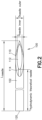
- a cannula 100 in accordance with the present disclosure includes a sidewall 102 extending between a distal end 110 and a proximal end 120.
- the sidewall 102 has an outer diameter D needle _ outer and an inner diameter D needle _ inner , with a difference between the outer diameter D needle _ outer and the inner diameter D needle _ inner defining a wall thickness.
- the inner diameter D needle _ inner of the sidewall 102 defines a lumen whose cross-section is substantially circular and through which a medicament, blood, or other fluid can flow.
- the outer diameter D needle _ outer of the sidewall 102 may be equivalent to industry-standard nominal sizes for a selected cannula gauge (G), with the gauge size defining the limits for the outer diameter.
- G cannula gauge
- a 27G cannula will have an outer diameter of between 0.400 and 0.420 mm
- a 29G cannula will have an outer diameter of between 0.324 and 0.351 mm
- a 30G cannula will have an outer diameter of between 0.298 and 0.320 mm.
- the outer diameter D needle _ outer of the sidewall 102 may be substantially constant between the proximal end 120 and the distal end 110.
- the distal end 110 may include a beveled tip configured for piercing a patient's skin to create a vascular access site.
- the beveled tip defines an opening 112 into the lumen.
- the opening has a proximal end 114.
- the proximal end 120 of the cannula 100 is configured for connection to a distal end 204 of a syringe 200.
- the overall length L needle of the cannula 100 extends from the proximal-most end of the sidewall 102 to the distal-most end of the sidewall 102, including the length of the beveled tip of the distal end 110.
- the syringe 200 (which may be formed of plastic or glass, typically glass) includes a sidewall 202 having an inner diameter D barrel .
- the inner diameter D barrel depends on the volume of the barrel and the associated volume of drug to be injected.
- the barrel may be a 1mLL (1 mm long) or 2.25mLL (2.25 mm long) barrel, with the 1mLL barrel having an inner diameter D barrel of 6.35mm +/- 0.01mm and the 2.25mLL barrel having an inner diameter D barrel of 8.65mm +/- 0.2mm.
- the sidewall 202 tapers toward the distal end 204 of the syringe 200 where the cannula 100 is connected (e.g., glued).
- the sidewall 202 tapers in a transition region 206 from the inner diameter D barrel to a smaller diameter slightly lower than the outer diameter D needle _ outer of the cannula 100.
- the transition region 206 ends at a break 208, at which point the inner diameter of the sidewall 202 is approximately equal to the inner diameter D needle _ inner of the cannula 100.
- An elastomeric stopper 220 is slidably disposed within the sidewall 202 and can be advanced distally to expel fluid from the syringe 200 through the cannula 100.
- the stopper 220 may be affixed to the end of a plunger (not shown) that can be depressed by a clinician's finger(s).
- the aforementioned overall length L needle extends from the proximal-most end of the sidewall 102 to the distal-most end of the sidewall 102.
- the theoretical hydrodynamic length L hydrodynamic theoretical needle extends from the proximal-most end of the sidewall 102 to the proximal end 114 of the opening 112 of the beveled tip.
- the actual hydrodynamic length L hydrodynamic extends from the break 208 of the syringe 200 (where the diameter of the barrel is the smallest) to the proximal end 114 of the opening 112 of the beveled tip.
- Injection force required to inject a fluid from the syringe 200 through the cannula 100 is a complex calculation involving many factors. However, this calculation can be simplified for many relevant applications so long as stopper speed within the syringe is not abnormally high, and so long as dynamic viscosity of the fluid injected in not abnormally low.
- Equation 1 Equation 1
- the flow factor K 1 is presented in units of distance and, for most cannulas used in medical devices, is typically in a range of 10,000 meters and 10,000,000 meters.
- the flow factor K 1 is related to injection time, with a relatively lower flow factor K 1 correlating to a faster injection time and a relatively higher flow factor K 1 correlating to a longer injection time for the same volume of fluid injected.
- the factor K 1 is lowered, the injection force required to inject the drug contained into the syringe is lowered too. In lowering the required injection force, the injection is easier to perform and/or a more viscous drug may be inject into a patient's skin without considerably increasing the required injection force.
- the cannula 100 can be characterized by what may generally be termed a "length-to-diameter ratio" of the cannula - with the length-to-diameter ratio defined herein as a ratio of the theoretical hydrodynamic needle length to the fourth power of the inner diameter (L hydrodynamic theoretical needle / D needle_inner 4 ) or as a ratio of the actual hydrodynamic needle length to the fourth power of the hydrodynamic diameter (L hydrodynamic / D hydrodynamic 4 ).
- the inner diameter D needle _ inner of the cannula 100 is typically ascertained from a dimensional drawing of the cannula 100, and, due to manufacturing limitations, is not necessarily reflective of a measurement from the actual cannula 100.
- gauge pins are typically used.
- gauge pins have their own limitations, notably in that gauge pins are incapable of reliably measuring a tapered bore and other inconsistencies in the bore introduced by manufacturing.
- the hydrodynamic diameter D hydrodynamic can be experimentally derived by pushing fluid through the cannula at a known or deduced flow rate.
- the flow rate may be deduced by measuring the mass of fluid during a given time period and by knowing the density of the fluid. Based on this flow rate, the ratio of the actual hydrodynamic needle length to the fourth power of the hydrodynamic diameter (L hydrodynamic / D hydrodynamic 4 ) can be deduced via the fluid viscosity and test pressure. If the actual hydrodynamic length L hydrodynamic of the needle is known, the hydrodynamic diameter D hydrodynamic may then be deduced.
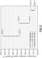
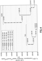
- FIGS. 3 and 4 graphs are providing illustrating the length-to-diameter ratio (i.e., the ratio of the theoretical hydrodynamic needle length to the fourth power of the inner diameter, L hydrodynamic theoretical needle / D needle_inner 4 ) and the flow factor K 1 , respectively, for various syringes that include a cannula having an 8mm exposed length, according to aspects of the disclosure.
- an acceptable range of the length-to-diameter ratio (L hydrodynamic theoretical needle / D needle_inner 4 ) is provided for each of a 27G, 29G and 30G cannula.
- the length-to-diameter ratio of the 27G cannula is between 8.5 ⁇ 10 11 m -3 and 1.5 ⁇ 10 12 m -3
- the length-to-diameter ratio of the 29G cannula is between 2 ⁇ 10 12 m -3 and 4. 5 ⁇ 10 12 m -3
- the length-to-diameter ratio of the 30G cannula is between 4.5 ⁇ 10 12 m -3 and 8.5 ⁇ 10 12 m -3 .
- An acceptable range of the length-to-diameter ratio across all of the or 27G, 29G and 30G cannulas is thus between 8.5 ⁇ 10 11 and 8.5 ⁇ 10 12 m -3 , according to aspects of the present disclosure.
- an acceptable range of a flow factor K 1 is provided for 1mLL syringes having a 27G, 29G or 30G cannula and for 2.25 mLL syringes having a 27G, 29G or 30G cannula.
- the flow factor K 1 of the 1mLL syringes is between 34,000m and 63,000m for the 27G cannula, 79,000m and 1.9 ⁇ 10 5 m for the 29G cannula, and 1.8 ⁇ 10 5 m and 3.6 ⁇ 10 5 m for the 30G cannula
- the flow factor K 1 of the 2.25mLL syringes is between 1.1 ⁇ 10 5 m and 2.2 ⁇ 10 5 m for the 27G cannula, 2.7 ⁇ 10 5 m and 6.6 ⁇ 10 5 m for the 29G cannula, 6.0 ⁇ 10 5 m and 1.3 ⁇ 10 6 m for the 30G cannula.
- An acceptable range of the flow factor K 1 across the 1mLL and 2.25mLL syringes and all of the 27G, 29G and 30G cannulas is thus between 34,000 and 1.3 ⁇ 10 6 meters.
Landscapes
- Health & Medical Sciences (AREA)
- Vascular Medicine (AREA)
- Engineering & Computer Science (AREA)
- Anesthesiology (AREA)
- Biomedical Technology (AREA)
- Heart & Thoracic Surgery (AREA)
- Hematology (AREA)
- Life Sciences & Earth Sciences (AREA)
- Animal Behavior & Ethology (AREA)
- General Health & Medical Sciences (AREA)
- Public Health (AREA)
- Veterinary Medicine (AREA)
- Infusion, Injection, And Reservoir Apparatuses (AREA)
Priority Applications (7)
| Application Number | Priority Date | Filing Date | Title |
|---|---|---|---|
| EP23183866.5A EP4487890A1 (de) | 2023-07-06 | 2023-07-06 | Dünnwandige kanüle |
| EP24743991.2A EP4739374A1 (de) | 2023-07-06 | 2024-06-28 | Dünnwandige kanüle |
| PCT/US2024/035995 WO2025010191A1 (en) | 2023-07-06 | 2024-06-28 | Thin wall cannula |
| AU2024291169A AU2024291169A1 (en) | 2023-07-06 | 2024-06-28 | Thin wall cannula |
| CN202480045411.4A CN121511105A (zh) | 2023-07-06 | 2024-06-28 | 薄壁插管 |
| KR1020267003807A KR20260035961A (ko) | 2023-07-06 | 2024-06-28 | 박벽 캐뉼러 |
| MX2026000026A MX2026000026A (es) | 2023-07-06 | 2026-01-07 | Canula de pared delgada |
Applications Claiming Priority (1)
| Application Number | Priority Date | Filing Date | Title |
|---|---|---|---|
| EP23183866.5A EP4487890A1 (de) | 2023-07-06 | 2023-07-06 | Dünnwandige kanüle |
Publications (1)
| Publication Number | Publication Date |
|---|---|
| EP4487890A1 true EP4487890A1 (de) | 2025-01-08 |
Family
ID=87158507
Family Applications (1)
| Application Number | Title | Priority Date | Filing Date |
|---|---|---|---|
| EP23183866.5A Pending EP4487890A1 (de) | 2023-07-06 | 2023-07-06 | Dünnwandige kanüle |
Country Status (1)
| Country | Link |
|---|---|
| EP (1) | EP4487890A1 (de) |
Citations (3)
| Publication number | Priority date | Publication date | Assignee | Title |
|---|---|---|---|---|
| US20020138050A1 (en) * | 1995-12-22 | 2002-09-26 | Jorgen K. Smedegaard | Injection needle |
| US20170216529A1 (en) * | 2014-08-06 | 2017-08-03 | Xeris Pharmaceuticals, Inc. | Syringes, kits, and methods for intracutaneous and/or subcutaneous injection of pastes |
| US20200268987A1 (en) * | 2019-02-26 | 2020-08-27 | Minhong Yu | Cannula Assembly for Higher Viscosity Injectable Drugs |
-
2023
- 2023-07-06 EP EP23183866.5A patent/EP4487890A1/de active Pending
Patent Citations (3)
| Publication number | Priority date | Publication date | Assignee | Title |
|---|---|---|---|---|
| US20020138050A1 (en) * | 1995-12-22 | 2002-09-26 | Jorgen K. Smedegaard | Injection needle |
| US20170216529A1 (en) * | 2014-08-06 | 2017-08-03 | Xeris Pharmaceuticals, Inc. | Syringes, kits, and methods for intracutaneous and/or subcutaneous injection of pastes |
| US20200268987A1 (en) * | 2019-02-26 | 2020-08-27 | Minhong Yu | Cannula Assembly for Higher Viscosity Injectable Drugs |
Similar Documents
| Publication | Publication Date | Title |
|---|---|---|
| KR102862025B1 (ko) | 혈관 접근 기구용 주사기-기반 전달 장치 | |
| US9393382B2 (en) | High-flow tapered peripheral IV catheter with side outlets | |
| JP3860835B2 (ja) | 特に医療を目的とする圧力を制御して流体を取扱う装置 | |
| RU2130324C1 (ru) | Подкожная игла | |
| CN202724337U (zh) | 具有螺旋缝隙的导管 | |
| US20050177117A1 (en) | Needle with lateral aperture | |
| JP2011520555A (ja) | 円錐状拡大チップ | |
| JP2023161010A (ja) | 注射器アセンブリ | |
| US20120078095A1 (en) | High-flow tapered peripheral iv catheter with side outlets | |
| KR20140019786A (ko) | 혈관 니들 시스템 | |
| US5133362A (en) | Needle for use with vacuum test tube blood sampling systems | |
| CN111821560B (zh) | 导管插入装置以及针 | |
| EP4596003A1 (de) | Dünnwandige kanüle | |
| CN103446656A (zh) | 防打折神经阻滞留置导管针 | |
| WO2004006996A1 (ja) | 注射針および導液具 | |
| WO2025010191A1 (en) | Thin wall cannula | |
| EP2120742A1 (de) | Epiduralnadel und epiduralvorrichtung | |
| US20240082509A1 (en) | Low dead space needle | |
| CN215653096U (zh) | 一种无损针 | |
| US10342957B2 (en) | Dual passageway safety syringe for injecting a medicament into non-venous tissue | |
| WO2023154911A1 (en) | Point of care collection and transfer device with luer lock access device and syringe compatibility | |
| CN115813761A (zh) | 一种用于抽取药液的注射器的防刺伤钝针及其使用方法 | |
| US20230414868A1 (en) | Medical device | |
| EP3919100A1 (de) | Verweilnadel zur subkutanen verabreichung | |
| CN114901327A (zh) | 注射泵针机械 |
Legal Events
| Date | Code | Title | Description |
|---|---|---|---|
| PUAI | Public reference made under article 153(3) epc to a published international application that has entered the european phase |
Free format text: ORIGINAL CODE: 0009012 |
|
| STAA | Information on the status of an ep patent application or granted ep patent |
Free format text: STATUS: THE APPLICATION HAS BEEN PUBLISHED |
|
| AK | Designated contracting states |
Kind code of ref document: A1 Designated state(s): AL AT BE BG CH CY CZ DE DK EE ES FI FR GB GR HR HU IE IS IT LI LT LU LV MC ME MK MT NL NO PL PT RO RS SE SI SK SM TR |
|
| STAA | Information on the status of an ep patent application or granted ep patent |
Free format text: STATUS: REQUEST FOR EXAMINATION WAS MADE |
|
| 17P | Request for examination filed |
Effective date: 20250605 |
|
| STAA | Information on the status of an ep patent application or granted ep patent |
Free format text: STATUS: EXAMINATION IS IN PROGRESS |
|
| 17Q | First examination report despatched |
Effective date: 20260114 |