EP4487921A1 - Régulateur de la demande pulmonaire - Google Patents
Régulateur de la demande pulmonaire Download PDFInfo
- Publication number
- EP4487921A1 EP4487921A1 EP23183131.4A EP23183131A EP4487921A1 EP 4487921 A1 EP4487921 A1 EP 4487921A1 EP 23183131 A EP23183131 A EP 23183131A EP 4487921 A1 EP4487921 A1 EP 4487921A1
- Authority
- EP
- European Patent Office
- Prior art keywords
- demand regulator
- release
- lung demand
- annular element
- locking mechanism
- Prior art date
- Legal status (The legal status is an assumption and is not a legal conclusion. Google has not performed a legal analysis and makes no representation as to the accuracy of the status listed.)
- Pending
Links
Images



Classifications
-
- A—HUMAN NECESSITIES
- A62—LIFE-SAVING; FIRE-FIGHTING
- A62B—DEVICES, APPARATUS OR METHODS FOR LIFE-SAVING
- A62B9/00—Component parts for respiratory or breathing apparatus
- A62B9/02—Valves
- A62B9/022—Breathing demand regulators
- A62B9/025—Breathing demand regulators with tilting opening action
-
- A—HUMAN NECESSITIES
- A62—LIFE-SAVING; FIRE-FIGHTING
- A62B—DEVICES, APPARATUS OR METHODS FOR LIFE-SAVING
- A62B7/00—Respiratory apparatus
- A62B7/02—Respiratory apparatus with compressed oxygen or air
- A62B7/04—Respiratory apparatus with compressed oxygen or air and lung-controlled oxygen or air valves
-
- A—HUMAN NECESSITIES
- A62—LIFE-SAVING; FIRE-FIGHTING
- A62B—DEVICES, APPARATUS OR METHODS FOR LIFE-SAVING
- A62B18/00—Breathing masks or helmets, e.g. affording protection against chemical agents or for use at high altitudes or incorporating a pump or compressor for reducing the inhalation effort
- A62B18/02—Masks
-
- A—HUMAN NECESSITIES
- A62—LIFE-SAVING; FIRE-FIGHTING
- A62B—DEVICES, APPARATUS OR METHODS FOR LIFE-SAVING
- A62B18/00—Breathing masks or helmets, e.g. affording protection against chemical agents or for use at high altitudes or incorporating a pump or compressor for reducing the inhalation effort
- A62B18/08—Component parts for gas-masks or gas-helmets, e.g. windows, straps, speech transmitters, signal-devices
-
- A—HUMAN NECESSITIES
- A62—LIFE-SAVING; FIRE-FIGHTING
- A62B—DEVICES, APPARATUS OR METHODS FOR LIFE-SAVING
- A62B9/00—Component parts for respiratory or breathing apparatus
- A62B9/02—Valves
- A62B9/022—Breathing demand regulators
-
- A—HUMAN NECESSITIES
- A62—LIFE-SAVING; FIRE-FIGHTING
- A62B—DEVICES, APPARATUS OR METHODS FOR LIFE-SAVING
- A62B9/00—Component parts for respiratory or breathing apparatus
- A62B9/04—Couplings; Supporting frames
-
- B—PERFORMING OPERATIONS; TRANSPORTING
- B63—SHIPS OR OTHER WATERBORNE VESSELS; RELATED EQUIPMENT
- B63C—LAUNCHING, HAULING-OUT, OR DRY-DOCKING OF VESSELS; LIFE-SAVING IN WATER; EQUIPMENT FOR DWELLING OR WORKING UNDER WATER; MEANS FOR SALVAGING OR SEARCHING FOR UNDERWATER OBJECTS
- B63C11/00—Equipment for dwelling or working underwater; Means for searching for underwater objects
- B63C11/02—Divers' equipment
- B63C11/12—Diving masks
- B63C11/14—Diving masks with forced air supply
-
- B—PERFORMING OPERATIONS; TRANSPORTING
- B63—SHIPS OR OTHER WATERBORNE VESSELS; RELATED EQUIPMENT
- B63C—LAUNCHING, HAULING-OUT, OR DRY-DOCKING OF VESSELS; LIFE-SAVING IN WATER; EQUIPMENT FOR DWELLING OR WORKING UNDER WATER; MEANS FOR SALVAGING OR SEARCHING FOR UNDERWATER OBJECTS
- B63C11/00—Equipment for dwelling or working underwater; Means for searching for underwater objects
- B63C11/02—Divers' equipment
- B63C11/12—Diving masks
- B63C11/16—Diving masks with air supply by suction from diver, e.g. snorkels
-
- B—PERFORMING OPERATIONS; TRANSPORTING
- B63—SHIPS OR OTHER WATERBORNE VESSELS; RELATED EQUIPMENT
- B63C—LAUNCHING, HAULING-OUT, OR DRY-DOCKING OF VESSELS; LIFE-SAVING IN WATER; EQUIPMENT FOR DWELLING OR WORKING UNDER WATER; MEANS FOR SALVAGING OR SEARCHING FOR UNDERWATER OBJECTS
- B63C11/00—Equipment for dwelling or working underwater; Means for searching for underwater objects
- B63C11/02—Divers' equipment
- B63C11/18—Air supply
- B63C11/22—Air supply carried by diver
- B63C11/24—Air supply carried by diver in closed circulation
Definitions
- a typical SCBA may comprise a breathing gas cylinder, a face mask, and a pneumatic system for delivering breathing gas from the cylinder to the face mask for the user to breathe.
- the pneumatic system may comprise a lung demand regulator (which may also referred be to as a "regulator", "LDR” or “LDV”) configured to control the supply of breathing air from the SCBA to a user via the face mask.
- LDR lung demand regulator
- LDR low-regulator
- LDV lung demand regulator
- These regulators are commonly releasable from the face mask, and often include control features such as a first breath switch-on mechanism, a switch off mechanism, a purge mechanism, and a locking/unlocking mechanism for connecting the regulator to the face mask.
- a lung demand regulator for a breathing apparatus comprising: a housing; a connection mechanism configured to releasably connect the lung demand regulator to a face mask, the connection mechanism comprising one or more release elements configured to be activated by a user to release the connection mechanism, to thereby disconnect the lung demand regulator from the face mask, wherein a position of the one or more release elements are rotationally adjustable relative to the housing.
- Rotationally adjustable should be understood to mean that the one or more release elements can be positioned in any of a plurality of rotational positions relative to the housing. Relative to the housing should be understood to mean that the position of the one or more release elements can be adjusted without also needing to adjust the position of the housing.
- the lung demand regulator may be rotationally adjustable relative to the face mask or freely rotatable relative to the face mask while connected thereto.
- the lung demand regulator may additionally be rotationally positional at a plurality of rotational detents relative to the face mask.
- the lung demand regulator may be used as part of a self-contained breathing apparatus (SCBA), but it should be understood that the lung demand regulator may also have applications in other types of breathing apparatus, such as self-contained underwater breathing apparatus (SCUBA) and emergency escape breathing apparatus.
- SCBA self-contained breathing apparatus
- SCUBA self-contained underwater breathing apparatus
- emergency escape breathing apparatus emergency escape breathing apparatus
- the lung demand regulator may further comprise an outlet port extending from the housing which may provide fluid communication between the lung demand regulator and the face mask.
- the one or more release elements may be arranged about a circumference of the outlet port. The positions of the one or more release elements may be rotationally adjustable about the circumference of the outlet port.
- the outlet port may provide a path for breathing gas to flow from the lung demand regulator to the face mask.
- the outlet port may also provide a path for gas exhaled by a user to flow from the face mask to the lung demand regulator.
- the outlet port may be substantially cylindrical.
- the one or more release elements may be provided on an annular element arranged to encircle the outlet port and may be configured to be rotationally adjustable relative to the outlet port, or around the outlet port.
- Each of the one or more release elements may be a button, optionally a biased button, configured to be depressible in a radial direction relative to the annular element to thereby release the connection mechanism.
- a biased button should be understood to mean a button comprising a spring or other biasing components configured to urge the button towards its unpressed state, where the user must overcome the biasing of the button in order to depress the button and release the connection mechanism.
- buttons may be made from the same material, or optionally a different material than that of the housing of the lung demand regulator.
- the external surface of the buttons which a user interacts with may be formed of a rubberised or otherwise high friction material to make pressing the buttons easier.
- the lung demand regulator may further comprise a release element locking mechanism configured to releasably lock the rotational position of the annular element relative to the housing.
- the outlet port of the lung demand regulator may comprise a receiving portion configured to receive the release element locking mechanism. Once the release element locking mechanism is received by the receiving portion, the release element locking mechanism may inhibit rotational adjustment of the annular element.
- the lung demand regulator When the release element locking mechanism is set so as to inhibit rotational adjustment of the annular element, the lung demand regulator is said to be in a locked configuration. When the release element locking mechanism is set so as to allow rotational adjustment of the annual element, the lung demand regulator is said to be in an unlocked configuration.
- the release element locking mechanism may be removable from the receiving portion when the lung demand regulator is not connected to the face mask, thereby permitting rotational adjustment of the annular element.
- the release element locking mechanism may not be removable from the receiving portion when the lung demand regulator is connected to the face mask, thereby inhibiting rotational adjustment of the annular element.
- the receiving portion may comprise a threaded portion onto which the release element locking mechanism is threaded. Tightening the release element locking mechanism onto the receiving portion may cause rotational adjustment of the annular element to be inhibited.
- the release element locking mechanism may comprise a ratcheting mechanism whereby pushing the release element locking mechanism further onto the outlet port causes the clamping force acting on the annular element to be increased.
- the housing of the lung demand regulator may comprise a first keying feature and the annular element may comprise a complementary second keying feature.
- the release element locking mechanism may be lockable when the annular element is in a rotational position where the first keying feature and second keying feature are aligned.
- the release element locking mechanism may not be lockable when the annular element is in a rotational position where the first keying feature and the second keying feature are not aligned.
- the first keying feature may be disposed on a circumference of the outlet port.
- the annular element may comprise a plurality of second keying features, where each corresponding to a rotational position of the annular element. Any one of the plurality of second keying features may be aligned with the first keying feature by rotational adjustment of the annular element so as to allow the release element locking mechanism to be lockable in the rotational position corresponding to a chosen second keying feature.
- the annular element may comprise a first keying feature and the housing may comprise a plurality of second keying features where each second keying feature corresponds to a different rotational position to which the annular element can be adjusted.
- the outlet port may comprise a plurality of first keying features; and the plurality of second keying features may comprise one or more groups of second keying features. Each group may correspond to a rotational position of the annular element. Each of the one or more groups may be configured to align with the plurality of first keying features by rotational adjustment of the annular element so as to allow the release element locking mechanism to be lockable in the rotational position corresponding to a chosen group.
- the plurality of first keying features may be disposed equidistant around the circumference of the outlet port.
- the plurality of second keying features may be disposed equidistant around a circumference of the annular element.
- the first keying feature or plurality of first keying features may also be considered to be recessed keying features.
- a recessed keying feature may comprise a cut-out or notch in the annular element.
- the second keying feature of plurality of second keying features may also be considered to be raised keying features.
- a raised keying feature may comprise a projection or widened section of the outlet port. The cut-out or notch may be of the same or greater depth as the projection or widened section is tall.
- a breathing system comprising a lung demand regulator according to the first aspect.
- the aspects described herein provide a mechanism for rotationally adjusting the position of one or more release elements on a lung demand regulator, hence enabling a greater degree of user customisability.
- the breathing apparatus 10 is a self-contained breathing apparatus (SCBA) and comprises a support frame or backplate 12, straps 14 for securing the SCBA to a user, a breathing gas cylinder 16, a face mask 18, a lung demand regulator 100 connectable to the face mask 18, and a pneumatics system 20 for delivering breathing gas from the cylinder 16 via a hose or flexible conduit 22 to the lung demand regulator 100, to thereby deliver breathing gas to the user wearing the face mask 18 on demand.
- the breathing apparatus 10 may further comprise other components or systems which are not shown, including but not limited to a waist belt, harness, an electrical system, a monitoring system, or a communications system.
- the lung demand regulator 100 is also referred to as the regulator 100 throughout.
- the breathing apparatus 10 is a self-contained breathing apparatus (SCBA), but it should be understood that the regulator 100 may also have applications in other types of breathing apparatus, such as self-contained underwater breathing apparatus (SCUBA) and emergency escape breathing apparatus.
- SCBA self-contained breathing apparatus
- SCUBA self-contained underwater breathing apparatus
- emergency escape breathing apparatus emergency escape breathing apparatus
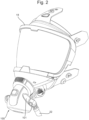
- Figure 2 schematically shows a face mask 18 attached to the regulator 100.
- a hose 22 of the pneumatics system 20 is connected to an inlet 101 of the regulator 100 to provide breathing gas from the cylinder 16.
- the pneumatics system 20 may comprise a first-stage pressure reducer which reduces the pressure of the breathing air from the cylinder which may be stored at several hundred bar, to an intermediate pressure for provision to the regulator 100 via the hose 22. The intermediate pressure may be too high for the breathing gas to be provided directly to the user to breathe.
- the regulator 100 may further comprise a second-stage pressure reducer which further reduces the pressure of the breathing gas to a suitable pressure for delivery to the user to breathe. In other arrangements, more than two or fewer than two pressure reducers may be provided.
- the regulator 100 comprises an outlet port 130 which directs breathing gas from the regulator 100 to the face mask 18.
- the outlet port 130 also allows gas exhaled by the user to flow from the face mask 18 back into the regulator 100.
- the regulator 100 also comprises a connection mechanism 120, itself comprising an annular ring 124.
- the internal diameter of the annulus 125 of the annular ring 124 is such as to allow the outlet port 130 to fit through it.
- the connection mechanism 120 is rigidly fixed to the regulator 100.
- the connection mechanism 120 is responsible for mechanically and fluidically connecting the regulator 100 to the face mask 18.
- the outlet port 130 is generally circular in cross sectional profile and comprises a receiving portion 132 (shown in Figure 4 ).
- the connection mechanism 120 is received by the receiving portion 132 when annular ring 124 is fit around and pushed down the length of the outlet port 130.
- the receiving portion 132 acts as a seat, against which the connection mechanism abuts.
- Release elements 122 are disposed on opposing sides of the external circumference of the annular element 124. Release elements 122 are configured to be pressed inwards (i.e., radially inwards relative to the annular element 124) by a user to cause the face mask 18 to be connected and/or disconnected from the regulator.
- the connection mechanism 120 may comprise one or more latch elements 141 in operative connection with the release elements 122, which are configured to secure the regulator 100 to the face mask 18.
- the release elements 122 may be configured to move the latch elements 141 between a latched position, in which the regulator 100 is secured to the mask 18, and an unlatched position, in which the regulator 100 is free to be removed from the mask 18.
- the release elements 122 are spring loaded so as to tend towards their unpressed state when a user is not pressing them, thereby preventing the face mask 18 from unintentionally disconnecting from the regulator 100.
- the release elements 122 are spring loaded, they may not need to be actively depressed by the user in order to connect the regulator 100 to the face mask 18.
- the connection mechanism 120 may comprise one or more ramped portions, such as on the latch elements 141, which engage with a portion of the face mask 18, and thereby enable the connection mechanism 120 to be automatically released during attachment of the regulator 100 to the mask 18 by applying an axial force to urge the regulator 100 towards the mask 18.
- connection mechanism 120 is rotatable around the outlet port 130, thereby allowing the user to rotationally adjust the positions of the release elements 122 relative to the regulator 100.
- the annular element 124 is configured to be rotatable about the outlet port 130.
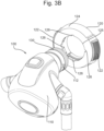
- Figure 3A shows the connection mechanism 120 in a rotational position where the release elements 122 are vertically aligned relative to the regulator 100, above and below the outlet port 130.
- Figure 3B shows the connection mechanism 120 in a rotational position where the release elements 122 are horizontally aligned relative to the regulator 100, either side of the outlet port 130. The user may rotationally adjust the connection mechanism 120 around the outlet port 130 to place the release elements 122 in any desired position.
- the annular element 124 is provided with recessed keying features 126, disposed inset around the circumference of the internal annulus 125. In the embodiment shown, there are four recessed keying features 126, however in other embodiments, there may be a different number. Each recessed keying feature 126 corresponds to a different rotational position of the connection mechanism 120.
- the outlet port 130 comprises two fixed raised keying features 112 opposingly disposed on the outlet port 130 (although different embodiments have a different number of fixed raised keying features 112).
- One of the raised keying features 112 is shown in Figures 3A and 3B .
- the raised keying features 112 are sized so as to widen the outlet port 130 at the location of the raised keying features 112 to be greater than the diameter of the internal annulus 125.
- the recessed keying features 126 are recessed at least to the same amount that the raised keying features 112 extend.
- connection mechanism 120 In order for the connection mechanism 120 to be received by the receiving portion 132, connection mechanism 120 must be rotated until the recessed keying features 126 of the annular element 124 are aligned with the raised keying features 112 of the outlet port. Once the connection mechanism 120 is rotationally adjusted to a position where the keying features are aligned, the connection mechanism 120 may be placed over the outlet port 130. As this is done so, the raised keying features 112 pass through the recessed keying features 126, allowing the connection mechanism 120 to reach the receiving portion 132. If the keying features are not aligned, the raised keying features 112 will interfere with the edge of the internal annulus 125 when the connection mechanism 120 is placed over the outlet port 130, thereby preventing the connection mechanism from abutting against the receiving portion 132.
- each recessed keying feature 126 corresponds to a different rotational position of the connection mechanism 120.
- the user may select the rotational position they desire for the connection mechanism 120 and align the corresponding recessed keying feature 126 with the raised keying feature 112 accordingly. Therefore, each recessed keying feature 126 effectively acts as a rotational detent which the user may select to lock the connection mechanism in the corresponding position 120.
- the recessed keying features 126 are grouped into pairs, with each pair of recessed keying features 126 corresponding to a different rotational position of the connection mechanism 120. In this case, the user must align a pair of recessed keying features 126 with both of the raised keying features 112 in order to install the connection mechanism 120 in the desired rotational position. In other embodiments, there may be groups of recessed keying features 126 larger than two. In these cases, the user would need to align all of the recessed keying features 126 in the selected group with each of the raised keying features 112.
- a release element locking mechanism is provided. This prevents the connection mechanism 120, and therefore the release elements 122, from unintentionally rotating around the outlet port 130.
- the release element locking mechanism places the regulator in a locked configuration where the rotational position of the connection mechanism cannot be adjusted.
- the outlet port 130 comprises an externally threaded portion 134.
- the externally threaded portion 134 receives the release element locking mechanism.
- the release element locking mechanism is a nut 140. Once the annular ring 124 is seated against the receiving portion 132, the nut 140 is threaded onto the threaded portion 134.
- the nut 140 comprises a flanged portion 142. As the nut 140 is further threaded onto the threaded portion 134, the flanged portion 142 contacts the connection mechanism 120. Further tightening of the nut 140, causes the nut 140 to clamp the connection mechanism 120 between the flanged portion 142 and the receiving portion 132.
- connection mechanism 120 is prevented from moving either along a longitudinal axis of the outlet port 130, or rotationally around the outlet port 130. Therefore, once the connection mechanism 120 is in this locked configuration, the rotational positions of the release elements 122 is fixed and cannot be unintentionally adjusted by the user.
- the locking mechanism 140 may be sufficient to lock the connection mechanism 120 in position without the keying features 112, 126 mentioned above.
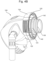
- Figure 4B shows the regulator 100 in the locked configuration.
- the connection mechanism 120 is seated against the receiving portion (not shown) and clamped in place by the flange 142 of the nut 140.
- the regulator 100 may be connected to the face mask 18. As shown in Figure 2 , when the regulator 100 is connected to the face mask 18, the connection mechanism 120 abuts against the face mask 18. As a result, the nut 140 cannot be accessed when the regulator 100 is connected to the face mask 18. In order to access and remove the nut 140 and therefore adjust the rotational position of the connection mechanism 120 and therefore the release elements 122, the regulator 100 must first be disconnected from the face mask 18.
Landscapes
- Health & Medical Sciences (AREA)
- Pulmonology (AREA)
- General Health & Medical Sciences (AREA)
- Business, Economics & Management (AREA)
- Emergency Management (AREA)
- Engineering & Computer Science (AREA)
- Mechanical Engineering (AREA)
- Ocean & Marine Engineering (AREA)
- Emergency Medicine (AREA)
- Life Sciences & Earth Sciences (AREA)
- Zoology (AREA)
- Respiratory Apparatuses And Protective Means (AREA)
Priority Applications (2)
| Application Number | Priority Date | Filing Date | Title |
|---|---|---|---|
| EP23183131.4A EP4487921A1 (fr) | 2023-07-03 | 2023-07-03 | Régulateur de la demande pulmonaire |
| CN202410879390.8A CN119236337A (zh) | 2023-07-03 | 2024-07-02 | 肺部需求调节器及呼吸系统 |
Applications Claiming Priority (1)
| Application Number | Priority Date | Filing Date | Title |
|---|---|---|---|
| EP23183131.4A EP4487921A1 (fr) | 2023-07-03 | 2023-07-03 | Régulateur de la demande pulmonaire |
Publications (1)
| Publication Number | Publication Date |
|---|---|
| EP4487921A1 true EP4487921A1 (fr) | 2025-01-08 |
Family
ID=87074815
Family Applications (1)
| Application Number | Title | Priority Date | Filing Date |
|---|---|---|---|
| EP23183131.4A Pending EP4487921A1 (fr) | 2023-07-03 | 2023-07-03 | Régulateur de la demande pulmonaire |
Country Status (2)
| Country | Link |
|---|---|
| EP (1) | EP4487921A1 (fr) |
| CN (1) | CN119236337A (fr) |
Citations (3)
| Publication number | Priority date | Publication date | Assignee | Title |
|---|---|---|---|---|
| WO2015027390A1 (fr) * | 2013-08-27 | 2015-03-05 | Honeywell International Inc. | Mécanisme d'entrée d'air frais pour masque facial utilisé sur un appareil respiratoire autonome à air comprimé à circuit ouvert |
| US20150217143A1 (en) * | 2014-02-05 | 2015-08-06 | Motorola Solutions, Inc | In-line accessory for a self-contained breathing apparatus |
| GB2575072A (en) * | 2018-06-27 | 2020-01-01 | Draeger Safety Uk Ltd | Demand regulator |
-
2023
- 2023-07-03 EP EP23183131.4A patent/EP4487921A1/fr active Pending
-
2024
- 2024-07-02 CN CN202410879390.8A patent/CN119236337A/zh active Pending
Patent Citations (3)
| Publication number | Priority date | Publication date | Assignee | Title |
|---|---|---|---|---|
| WO2015027390A1 (fr) * | 2013-08-27 | 2015-03-05 | Honeywell International Inc. | Mécanisme d'entrée d'air frais pour masque facial utilisé sur un appareil respiratoire autonome à air comprimé à circuit ouvert |
| US20150217143A1 (en) * | 2014-02-05 | 2015-08-06 | Motorola Solutions, Inc | In-line accessory for a self-contained breathing apparatus |
| GB2575072A (en) * | 2018-06-27 | 2020-01-01 | Draeger Safety Uk Ltd | Demand regulator |
Also Published As
| Publication number | Publication date |
|---|---|
| CN119236337A (zh) | 2025-01-03 |
Similar Documents
| Publication | Publication Date | Title |
|---|---|---|
| US7866319B2 (en) | Respirator exhalation unit | |
| US8196581B2 (en) | Mouthpiece supply valve | |
| EP2961490B1 (fr) | Équipement d'appareil respiratoire | |
| US11826590B2 (en) | Integrated manifold system | |
| EP4487921A1 (fr) | Régulateur de la demande pulmonaire | |
| US12128262B2 (en) | Connection apparatus for breathing apparatus | |
| US12239861B2 (en) | Low pressure alarm for self-contained breathing apparatus | |
| US5619988A (en) | First stage pressure regulator for emergency breathing apparatus | |
| EP3813955B1 (fr) | Régulateur à la demande | |
| CA2412695C (fr) | Systeme de livraison de gaz et etrier pneumatique pour reservoir de gaz sous pression | |
| EP1918001B1 (fr) | Soupape régulatrice de pression pour appareil respiratoire | |
| US20220080231A1 (en) | Dual Mode Breathing Apparatus | |
| US20250375628A1 (en) | Configurable Demand Regulator | |
| EP4356977A1 (fr) | Régulateur de demande | |
| US20260027388A1 (en) | Secure Threaded Connection | |
| EP4684840A1 (fr) | Raccord filete securise | |
| WO2024133163A1 (fr) | Régulateur de demande pulmonaire | |
| US20170036744A1 (en) | On-shore pressure helmet | |
| HK1135055A (en) | Respirator exhalation unit |
Legal Events
| Date | Code | Title | Description |
|---|---|---|---|
| PUAI | Public reference made under article 153(3) epc to a published international application that has entered the european phase |
Free format text: ORIGINAL CODE: 0009012 |
|
| STAA | Information on the status of an ep patent application or granted ep patent |
Free format text: STATUS: THE APPLICATION HAS BEEN PUBLISHED |
|
| AK | Designated contracting states |
Kind code of ref document: A1 Designated state(s): AL AT BE BG CH CY CZ DE DK EE ES FI FR GB GR HR HU IE IS IT LI LT LU LV MC ME MK MT NL NO PL PT RO RS SE SI SK SM TR |
|
| STAA | Information on the status of an ep patent application or granted ep patent |
Free format text: STATUS: REQUEST FOR EXAMINATION WAS MADE |
|
| 17P | Request for examination filed |
Effective date: 20250707 |
|
| STAA | Information on the status of an ep patent application or granted ep patent |
Free format text: STATUS: EXAMINATION IS IN PROGRESS |
|
| 17Q | First examination report despatched |
Effective date: 20260327 |