EP4487928A1 - Accessoire pour contrôleur de jeu vidéo, kit d'accessoire pour celui-ci et système d'entrée de jeu vidéo - Google Patents
Accessoire pour contrôleur de jeu vidéo, kit d'accessoire pour celui-ci et système d'entrée de jeu vidéo Download PDFInfo
- Publication number
- EP4487928A1 EP4487928A1 EP24181442.5A EP24181442A EP4487928A1 EP 4487928 A1 EP4487928 A1 EP 4487928A1 EP 24181442 A EP24181442 A EP 24181442A EP 4487928 A1 EP4487928 A1 EP 4487928A1
- Authority
- EP
- European Patent Office
- Prior art keywords
- video game
- trigger
- controller
- coupled
- mounting member
- Prior art date
- Legal status (The legal status is an assumption and is not a legal conclusion. Google has not performed a legal analysis and makes no representation as to the accuracy of the status listed.)
- Pending
Links
- 230000008878 coupling Effects 0.000 claims abstract description 70
- 238000010168 coupling process Methods 0.000 claims abstract description 70
- 238000005859 coupling reaction Methods 0.000 claims abstract description 70
- 230000033001 locomotion Effects 0.000 claims abstract description 33
- 238000012545 processing Methods 0.000 claims description 14
- 230000004044 response Effects 0.000 claims description 14
- 238000003384 imaging method Methods 0.000 claims description 7
- 238000013459 approach Methods 0.000 description 13
- 238000000034 method Methods 0.000 description 11
- 230000009286 beneficial effect Effects 0.000 description 9
- 238000010304 firing Methods 0.000 description 8
- 238000003825 pressing Methods 0.000 description 8
- 230000009471 action Effects 0.000 description 7
- XEEYBQQBJWHFJM-UHFFFAOYSA-N Iron Chemical compound [Fe] XEEYBQQBJWHFJM-UHFFFAOYSA-N 0.000 description 4
- 230000000295 complement effect Effects 0.000 description 4
- 230000003287 optical effect Effects 0.000 description 4
- 230000008901 benefit Effects 0.000 description 3
- 230000003993 interaction Effects 0.000 description 3
- 230000007935 neutral effect Effects 0.000 description 3
- 239000007787 solid Substances 0.000 description 3
- 238000004891 communication Methods 0.000 description 2
- 238000004590 computer program Methods 0.000 description 2
- 230000000994 depressogenic effect Effects 0.000 description 2
- 229910052742 iron Inorganic materials 0.000 description 2
- 230000009467 reduction Effects 0.000 description 2
- 230000003245 working effect Effects 0.000 description 2
- 230000006978 adaptation Effects 0.000 description 1
- 230000005540 biological transmission Effects 0.000 description 1
- 239000003990 capacitor Substances 0.000 description 1
- 230000008859 change Effects 0.000 description 1
- 238000010276 construction Methods 0.000 description 1
- 230000009977 dual effect Effects 0.000 description 1
- 230000000694 effects Effects 0.000 description 1
- 210000003414 extremity Anatomy 0.000 description 1
- 210000003811 finger Anatomy 0.000 description 1
- 230000006870 function Effects 0.000 description 1
- 230000005484 gravity Effects 0.000 description 1
- 210000004247 hand Anatomy 0.000 description 1
- 230000010365 information processing Effects 0.000 description 1
- 238000013507 mapping Methods 0.000 description 1
- 230000007246 mechanism Effects 0.000 description 1
- 239000002184 metal Substances 0.000 description 1
- 229910052751 metal Inorganic materials 0.000 description 1
- 238000012986 modification Methods 0.000 description 1
- 230000004048 modification Effects 0.000 description 1
- 230000000704 physical effect Effects 0.000 description 1
- 239000004033 plastic Substances 0.000 description 1
- 230000008569 process Effects 0.000 description 1
- 239000004065 semiconductor Substances 0.000 description 1
- 210000003813 thumb Anatomy 0.000 description 1
- 230000000007 visual effect Effects 0.000 description 1
Images




Classifications
-
- A—HUMAN NECESSITIES
- A63—SPORTS; GAMES; AMUSEMENTS
- A63F—CARD, BOARD, OR ROULETTE GAMES; INDOOR GAMES USING SMALL MOVING PLAYING BODIES; VIDEO GAMES; GAMES NOT OTHERWISE PROVIDED FOR
- A63F13/00—Video games, i.e. games using an electronically generated display having two or more dimensions
- A63F13/20—Input arrangements for video game devices
- A63F13/24—Constructional details thereof, e.g. game controllers with detachable joystick handles
-
- A—HUMAN NECESSITIES
- A63—SPORTS; GAMES; AMUSEMENTS
- A63F—CARD, BOARD, OR ROULETTE GAMES; INDOOR GAMES USING SMALL MOVING PLAYING BODIES; VIDEO GAMES; GAMES NOT OTHERWISE PROVIDED FOR
- A63F13/00—Video games, i.e. games using an electronically generated display having two or more dimensions
- A63F13/20—Input arrangements for video game devices
- A63F13/24—Constructional details thereof, e.g. game controllers with detachable joystick handles
- A63F13/245—Constructional details thereof, e.g. game controllers with detachable joystick handles specially adapted to a particular type of game, e.g. steering wheels
-
- A—HUMAN NECESSITIES
- A63—SPORTS; GAMES; AMUSEMENTS
- A63F—CARD, BOARD, OR ROULETTE GAMES; INDOOR GAMES USING SMALL MOVING PLAYING BODIES; VIDEO GAMES; GAMES NOT OTHERWISE PROVIDED FOR
- A63F13/00—Video games, i.e. games using an electronically generated display having two or more dimensions
- A63F13/90—Constructional details or arrangements of video game devices not provided for in groups A63F13/20 or A63F13/25, e.g. housing, wiring, connections or cabinets
- A63F13/98—Accessories, i.e. detachable arrangements optional for the use of the video game device, e.g. grip supports of game controllers
-
- A—HUMAN NECESSITIES
- A63—SPORTS; GAMES; AMUSEMENTS
- A63F—CARD, BOARD, OR ROULETTE GAMES; INDOOR GAMES USING SMALL MOVING PLAYING BODIES; VIDEO GAMES; GAMES NOT OTHERWISE PROVIDED FOR
- A63F13/00—Video games, i.e. games using an electronically generated display having two or more dimensions
- A63F13/80—Special adaptations for executing a specific game genre or game mode
- A63F13/837—Shooting of targets
-
- A—HUMAN NECESSITIES
- A63—SPORTS; GAMES; AMUSEMENTS
- A63F—CARD, BOARD, OR ROULETTE GAMES; INDOOR GAMES USING SMALL MOVING PLAYING BODIES; VIDEO GAMES; GAMES NOT OTHERWISE PROVIDED FOR
- A63F2300/00—Features of games using an electronically generated display having two or more dimensions, e.g. on a television screen, showing representations related to the game
- A63F2300/80—Features of games using an electronically generated display having two or more dimensions, e.g. on a television screen, showing representations related to the game specially adapted for executing a specific type of game
- A63F2300/8076—Shooting
Definitions
- the present disclosure relates to an attachment for a video game controller, an attachment kit for the same, and a video game input system.
- pressing a button to make the character jump may be viewed by such users as less intuitive than, say, moving the controller in an upward vertical direction (towards the head of the user, for example), which would thus make the controller move in a similar upward manner to that of the resulting jump performed by the character.
- some players may lack the dexterity/motor skills required to operate a video game controller in a proficient manner.
- the present disclosure seeks to alleviate or mitigate this issue.
- an attachment for a video game controller is provided in claim 1.
- an attachment kit for a video game controller is provided in claim 12.
- a video game input system is provided in claim 13.
- Coupled and “connected,” along with their derivatives, may be used herein to describe structural relationships between components of the apparatus for performing the operations herein. It should be understood that these terms are not intended as synonyms for each other. Rather, in embodiments of the present description, “connected” is used to indicate that two or more elements are in direct physical or electrical contact with each other while “coupled” is used to indicate two or more elements are in either direct or indirect (with other intervening elements between them) physical or electrical contact with each other, and/or that the two or more elements co-operate or communicate with each other (e.g., as in a cause an effect relationship).
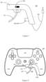
- the DualSense ® controller 100 is illustrated as a non-limiting example of a video game controller for which attachments and attachment kits according to embodiments of the present description may be suitable.
- a controller typically has two handle sections 101L,R and a central body 101C.
- Various controls are distributed over the controller, typically in local groups. Examples include a left button group 102L, which may comprise directional controls and/or one or more shoulder buttons, and similarly right button group 102R, which comprise function controls and/or one or more shoulder buttons.
- the controller also includes left and/or right thumbsticks 104L,R, which may optionally also be operable as buttons by pressing down on them.
- the controller may also comprise one or more system buttons 106, which typically cause interaction with an operating system of the entertainment device rather than with a game or other application currently running on it; such buttons may summon a system menu, or allow for recording or sharing of displayed content.
- the controller may comprise one or more other elements such as a touchpad 108, a light for optical tracking (not shown), a screen (not shown), haptic feedback elements (not shown), and the like.
- the present disclosure seeks to fulfil this need by providing an attachment for a conventional video game controller which, when coupled to the conventional controller, enables users to hold and operate the conventional controller as a firearm.
- an attachment enables users to play shooting games in a more intuitive/less difficult manner; the holding and operating of the conventional controller in a manner similar to that of a firearm bears a greater resemblance to the typical actions performed in such shooter games (that is, firing firearms) than, say, moving a thumbstick, pressing a button, or pulling a trigger located on the shoulder of controller (it will be appreciated that while the motion of the shoulder trigger itself resembles that of a firearm trigger, the handling of the controller while pulling the shoulder trigger does not resemble the holding of a firearm while pulling the trigger).
- the attachment thus enables users to adopt a more "point and shoot” approach to providing inputs to shooter games, which typically requires less so-called “fine” motor skills (finger/thumb movements, for example) and more so-called “gross” motor skills (limb/torso movements, for example) than that required to proficiently operate a video game controller in the conventional manner.
- this approach enables players with motor skill issues to rely on their gross motor skills (pointing the controller at the virtual object/character they want to shoot) more than their fine motor skills (the fine motor skills required for this point and shoot approach may be reduced to that of pulling the trigger), thus making operation of the controller more accessible to such users.
- the latest generations of conventional games controllers comprise location/orientation tracking means such as gyroscopes and accelerometers.
- location/orientation tracking means such as gyroscopes and accelerometers.
- Such tracking means may therefore be exploited to enable users to adopt this point and shoot approach to shooting games; while the user moves the controller towards the in-game object/character they want to shoot, the tracking means may transmit location/orientation data to the video games console executing the video game, and the location/orientation of the in-game gun being used by the user may be updated based on the transmitted location/orientation data.
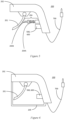
- an attachment 200 for a video game controller comprises trigger 201; mounting member 202 that is removably couplable to one of two handle portions of the video game controller, wherein trigger 201 is movably coupled to mounting member 202; and coupling means 203 coupling trigger 201 to the video game controller such that a motion of trigger 201 relative to mounting member 202 causes the video game controller to emit a control signal for controlling an operation of an entertainment device when coupling means 203 are coupled to the video game controller.
- FIG. 2 depicts coupling means 203 as signal generating circuitry 203A (pressure sensor 500 or proximity sensor 600, for example) and signal transmitting circuitry 203B (cable 700, for example)
- this embodiment is entirely non-limiting; other embodiments of coupling means 203 falling within the scope of the present disclosure shall be described later herein.
- Figure 2 depicts trigger 201 as being hingedly coupled to mounting member 202 via hinge 202A, skilled persons will appreciate that this embodiment is entirely non-limiting; trigger 201 may alternatively be slidably coupled to mounting member 202, as shall be discussed later herein.
- attachment 200 in use, consider a user playing a first person shooter (FPS) game on their video game console (entertainment device).
- the user may wish to play the FPS game in a manner that is more intuitive/accessible due to having dexterity/motor skill issues, or due to struggling to remember which buttons to press at which time in order to cause the in-game character to perform the desired actions.
- the user may couple their attachment 200 to their video game controller (such as controller 100).
- FIG. 3 depicts attachment 200 after having been coupled to video game controller 100.
- mounting member 202 has been coupled to one of the two handle portions of controller 100 (handle portion 101R, for example).
- This removable coupling may be achieved by making the profile of the part of mounting member 202 that couples with handle portion 101R to be complementary with the profile of handle portion 101R, for example. This may enable a secure fitting of mounting member 202 to handle portion 101R when coupled thereto, albeit one that may be overcome by the user should they wish to remove attachment 202 from controller 100.
- Coupling attachment 200 to one of the handle portions of controller 100 enables the user to hold the controller in a manner analogous to that of a firearm.
- This provides a more intuitive manner of providing control signals to the FPS game, as the user may adopt a "point and shoot approach" to playing the game.
- the user may aim their in-game character's gun by orienting the other of the two handle portions of controller 100 (hand portion 101L, for example) towards a region of the display screen that is displaying the video game, and subsequently fire the character's gun by pulling trigger 201.
- attachment 200 being coupled to handle portion 101R, and handle portion 101L being oriented towards the display screen for aiming
- converse arrangement that is, attachment 200 being coupled to handle portion 101L, and handle portion 101R being oriented towards the display screen for aiming
- detecting the orientation of controller 100 may be carried out by using gyroscopes/accelerometers, which are typically comprised within commonly-known video game controllers, especially those produced in recent years.
- gyroscopes/accelerometers typically comprised within commonly-known video game controllers, especially those produced in recent years.
- illuminating elements and cameras may be used to track controller orientation, as shall be discussed later herein.
- coupling means 203 detects the trigger pull and in response causes controller 100 to emit a control signal for firing the character's gun (that is, controlling operation of the entertainment device).
- pressure sensor 500 that is, generating circuitry 203A
- a signal a voltage, for example
- cable 700 that is, transmitting circuitry 203B
- controller 100 which causes controller 100 to emit the control signal.
- the user may rely on their gross motor skills more than their fine motor skills, thus making the game more accessible for the user. Additionally, playing the game in such a manner is more intuitive, as the actions the user performs (that is, orienting controller 100 and pulling trigger 201) bear a greater resemble to the in-game character's actions (that is, aiming and shooting a firearm) than does pressing controller buttons/manipulating controller joysticks.
- Embodiments of the present description comprise trigger 201, and mounting member 202 that is removably couplable to one of two handle portions of a video game controller (such as controller 100), wherein trigger 201 is movably coupled to mounting member 202.
- mounting member 202 may be coupled and decoupled to the video game controller as desired.
- a user may couple attachment 200 to controller 100 before playing an FPS game, and afterwards decouple it before playing, say, a turn-based strategy game where a point and shoot may not necessarily make gameplay more intuitive.
- the user may wish to keep attachment 200 coupled to controller 100 for the turn-based strategy game should they find it beneficial for them to do so.
- the user should be able to couple and decouple attachment at will.
- mounting member 202 may be formed/shaped so as to enable it to be removably coupled to controller 100.
- the profile of the part of mounting member 202 that couples with handle portion 101R may be formed/shaped so as to be complementary with the profile of handle portion 101R, for example.
- trigger 201 is coupled to mounting member 202 in such a manner so as to enable trigger 201 to move relative to mounting member 202.
- trigger 201 is depicted as being hingedly coupled to mounting member 202 such that trigger 201 rotates about hinge 202A when pulled.
- trigger 201 may be movably coupled to mounting member 202 in other ways.
- trigger 201 may be slidably coupled to mounting member 202 such that trigger 201 slides along rail 202B when pulled.
- trigger 201 may be hingedly coupled to mounting member 202 (via hinge 202A, for example), or trigger 201 may be slidably coupled to mounting member 202 (via rail 202B, for example).
- trigger 201 may beneficial to enable trigger 201 to return back to a predetermined position when not being pulled. This may be especially beneficial in the case where trigger 201 is slidably coupled to mounting member 202. This is because, once pulled, trigger 201 may not return to the position it was at prior to being pulled, unlike a hingedly coupled trigger, which may return to its original position (that is, position before being pulled) due to gravity, for example.
- trigger 201 is unable to return to its original position before being pulled again, then repeated firings (repeated pulling of trigger 201) may not be taken into account by controller 100, and thus may not emit repeated control signals for rapid firing of the in-game weapon, for example.
- proximity sensors typically produce a discrete signal when an object falls within a threshold distance away from them, but do not typically produce repeated signals if the object remains within the threshold distance.
- the object typically has to move out of the threshold distance before coming back within the threshold distance to cause another (subsequent) discrete signal to be output by the proximity sensor.
- means to move trigger 201 away from the proximity sensor may be beneficial to ensure that a repeated pulling thereof results in repeated signals being output by the proximity sensor.
- embodiments of the present description may comprise biasing means 204 for biasing a position of trigger 201 relative to mounting member 202 towards a predetermined position.
- biasing means 204 may comprise elastic element 204A (a spring, for example) and a piston 204B.
- Elastic element 204A may be disposed between the housing and shaft of piston 204B.
- other arrangements comprising an elastic element 204A may be used.
- biasing means that are typically integral to the thumbsticks of controller 100 may be leveraged.
- a coupling member a string, for example
- thumbstick's biasing means which are used to return the thumbstick to a so-called "neutral position" when not being manipulated
- unintended trigger pulls it may be desirable to reduce or eliminate unintended trigger pulls, and thus reduce or eliminate unintended control signals being emitted by controller 100 when attachment 200 is coupled thereto.
- unintended control signals may cause the entertainment device to perform processing that is undesired (shooting in wrong direction, selecting wrong in-game item, accidental purchases of in-game content, and the like).
- trigger guard 205 may be integral to mounting member 202 (that is, mounting member 202 and trigger guard may be formed as one object), or trigger guard 205 may be removably couplable thereto (by using some sort of snap fit mechanism(s), for example).
- trigger guard 205 prevents trigger 201 for being accidentally pulled due to chance interactions with other objects (clothes, holsters, and the like).
- embodiments of the present description may comprise safety catch 206 that is coupled to mounting member 202.
- safety catch 206 may comprise a switch, button or lever that, when engaged, prevents trigger 201 from moving when a force is applied thereto, and thus prevents unintended pulls of trigger 201.
- the specific workings of safety catch 206 may be thought of as analogous to that of commonly-known real-world firearms. Therefore, for brevity's sake, the workings of safety catch 206 shall not be discussed herein.
- trigger guard 205 and safety catch 206 may provide a more realistic gameplay experience to users. For example, when playing an FPS game, users may engage safety catch 206 and/or rest their trigger finger against trigger guard 205 when they do not intend to shoot, thus providing a more realistic/immersive FPS experience.
- trigger 201 and mounting member 202 enable the user to hold and operate controller 100 as if it were a firearm, and thus enable users to hold video game controllers in a more accessible/intuitive manner for certain video games.
- controller 100 In order to cause controller 100 to emit a control signal for controlling the operation of an entertainment device (a video game console, for example) in response to pulling trigger 201, means for coupling the motion of trigger 201 to the circuitry of the video game controller are required.
- an entertainment device a video game console, for example
- embodiments of the present description comprise coupling means 203 for coupling trigger 201 to the video game controller (controller 100, for example) such that a motion of trigger 201 relative to mounting member 202 causes the video game controller to emit a control signal for controlling an operation of an entertainment device when coupling means 203 are coupled to the video game controller.
- the present description contemplates two ways in which the coupling means may be realised, that is by using a mechanical link between trigger 201 and a thumbstick of the video game controller, and/or by using an electrical link between trigger 201 and a port of the video game controller.
- trigger 201 may be coupled to a video game controller such that motion of trigger 201 causes the video game controller to emit a control signal fall within the scope of the present disclosure.
- coupling means 203 may comprise coupling element 203C, wherein a first portion of coupling element 203C is coupled to trigger 201 and a second portion of coupling element 203C is removably couplable to a thumbstick of the video game controller (such as thumbstick 104R, for example).
- Coupling element 203C may threadlike in nature.
- coupling element 203C may copmrise a piece of thread, a piece of string, a wire, a cable, a chain, or the like.
- coupling element 203C may be of a more robust construction.
- coupling element 203C may comprise a rigid member made of metal, plastic, wood, or the like.
- the term "rigid" is used here in order to provide a distinction from the aforementioned threadlike coupling elements which may be employed, such threadlike coupling elements typically being flexible in nature.
- the first portion thereof may be fastened to trigger 201 using a knot (in the case of a threadlike coupling element 203C) or by using a mechanical fastening like a rivet, (wing) nut and bolt, or the like (in the case of a rigid coupling element 203C), and the second portion thereof may be formed as a loop which may be placed around the shaft of the thumbstick, for example.
- coupling element 203C When coupled to trigger 201 and thumbstick 104R, coupling element 203C effectively links the motion of thumbstick 104R to that of trigger 201. Thus, when the user pulls on trigger 201, thumbstick 104R is pulled by coupling element 203C.
- controller settings that is, the mapping between a given controller button/thumbstick/trigger and a given in-game action
- Modifying such controller setting is typically achieved by accessing an in-game settings menu.
- thumbstick 104R is manipulated (pulled), and the control signal emitted by controller 100 in response to the pulling of thumbstick 104R causes the in-game weapon to be fired.
- embodiments of the present description may comprise one or more pulleys 208 for adjusting a direction in which the thumbstick (such as thumbstick 104R, for example) moves when the motion of trigger 201 occurs, wherein the one or more pulleys 208 are coupled to mounting member 202, wherein the coupling member 203C makes contact with at least one of the pulleys 208 when coupled to the thumbstick.
- the thumbstick such as thumbstick 104R, for example
- the pulley(s) need not rotate about respective axes to provide the advantage of adjusting the direction in which thumbstick 104R is pulled.
- pulley(s) 208 may be a simple protrusion in mounting member 202 around which coupling element 203C may be disposed when coupled to thumbstick 104R.
- thumbsticks typically comprise integral biasing means which are used to return the thumbstick to a so-called "neutral position" when not being manipulated by the user.
- thumbstick 104R By mechanically linking thumbstick 104R to trigger 201, the latter may be returned into a predetermined position by the biasing means of the former when the latter is not being pulled.
- additional biasing means (such as that depicted in Figure 5 ) may be optionally employed in order to reduce the time taken for trigger 201 to return to the predetermined position.
- trigger 201 may be electrically coupled thereto.
- coupling means 203 may comprise generating circuitry 203A (pressure sensor 500 or proximity sensor 600, for example) configured to generate a signal in response to the motion of the trigger; and transmitting circuitry 203B (electrical cable 700, for example) configured to transmit the generated signal to a port of the video game controller, wherein at least a part of transmitting circuitry 203B is couplable to the port of the video game controller.
- generating circuitry 203A pressure sensor 500 or proximity sensor 600, for example
- transmitting circuitry 203B electrical cable 700, for example
- pressure sensor 203A generates a signal (a voltage, for example) when trigger 201 makes contact therewith, the contact arising due to the trigger being displaced by the pulling thereof by the user.
- cable 203B which is coupled to pressure sensor 203A and a port of controller 100 (a USB port, headphone jack, or the like), transmits the generated signal to controller 100, which causes controller 100 to emit a control signal.
- a mechanical linkage may be employed.
- a first portion of a threadlike coupling element (such as coupling element 203C, for example) may be coupled to the axle about which the magnet rotates and a second portion thereof may be coupled to trigger 201, with a portion of threadlike coupling element being wrapped around the axle.
- trigger 201 when trigger 201 is pulled, magnet 401 rotates relative to the coil(s) 402, which in turn causes a voltage to be output therefrom.
- Wireless receiver 800 may be similarly couplable with a port of controller 100 such as a USB port, headphone jack, or the like. However, wireless receiver 800 may be in wireless communication with another portion of transmitting circuitry 203B, such as wireless transmitter 801, for example, which may be coupled with generating circuitry 203A.
- coupling means 203 enables this operation of controller 100 (pulling trigger 100 coupled thereto, for example) to control the operation of an entertainment device (the firing of the in-game weapon in the FPS video game executed by a video game console, for example).
- Coupling means 203 thus enables users to play video games in a more accessible/intuitive manner.
- the gyroscopes/accelerometers present within commonly-known video game controllers may be utilised.
- Such gyroscopes/accelerometers are typically used to detect the orientation of controller 100 (and determine where the user is aiming).
- the user may move/orient their controller towards the in-game object/character they want to shoot.
- the gyroscopes/accelerometers within the controller may transmit location/orientation data to the video games console executing the video game, and the location/orientation of the in-game gun being used by the user may be updated based on the transmitted location/orientation data.
- the user may subsequently pull trigger 201 when the in-game gun is directed at the character/object the user wants to shoot, thereby causing the in-game gun to fire at the character/object.
- controller orientation/location tracking In order to improve controller orientation/location tracking (and thus make the point and shoot approach more accessible/ergonomic/accurate), it may be beneficial to track the controller using image processing techniques as well as (or alternatively to) using the motion tracking provided by the gyroscopes/accelerometers.
- a second attachment such as second attachment 900, for example
- This second attachment may be removably coupled to the part of the controller that will face the display screen when the user is taking aim (that is, the second handle portion of the controller - with attachment 200 being coupled to the first handle portion).
- This second attachment would enable the orientation/location of the controller to be tracked using cameras; the cameras may capture images of the user holding controller 100 (and the illuminating element(s)), and these images may be transmitted to an entertainment device.
- the transmitted images may be analysed by the entertainment device using commonly-known image processing techniques (computer vision techniques, for example) to determine a location and/or orientation of the illuminating element(s), and thus determine where the user is aiming.
- a third attachment (such as third attachment 1000, for example) comprising a sight 1001 for aiming.
- This third attachment may be removably couplable to the portion of controller 100 that lies between the two shoulder buttons of controller 100 (hereinafter referred to as the "yoke" of controller 100).
- the sight of this third attachment may enable the user to aim their controller more accurately, as does the sight of a real-world firearm.
- an attachment kit for a video game controller may comprise attachment 200; and at least one of: second attachment 900 for the video game controller, comprising one or more illuminating elements 901, and second mounting member 902 that is removably couplable to the other of the two handle portions of the video game controller, wherein the one or more illuminating elements 901 are coupled to second mounting member 902; and third attachment 1000 for the video game controller, comprising a sight 1001 for aiming, and third mounting member 1002 that is removably couplable to the video game controller, wherein sight 1001 is coupled to third mounting member 1002.
- the illuminating element(s) 901 thereof may be arranged in a predetermined pattern, such as a chevron or saltire, as non-limiting examples.
- a predetermined pattern such as a chevron or saltire
- this illuminating element 901 may be formed into a predetermined shape (pattern), such as a circle, triangle, cross, square, or the like. Skilled persons will appreciate that such forming may also be carried out on each of a plurality of illuminating elements 901, should such a plurality be present in second attachment 900.
- the location/orientation tracking of controller 100 using image processing technique may be made more accurate. This is because the captured images of second attachment 900 during use may be analysed to identify the predetermined pattern of illuminating element(s) 901, and the orientation/location of this predetermined pattern as captured in the image may be determined by evaluating it against a datum orientation/location stored in, say, the memory of the entertainment device carrying out the image processing, for example.
- second attachment 900 may comprise an electrical cable (not shown) that is couplable with a port of controller 100, such an electrical cable enabling second attachment to draw electrical power from controller 100.
- second attachment 900 may comprise a power source such as a (rechargeable) battery, for example.
- third mounting member 1002 thereof may be couplable with a port of controller 100.
- a port such as a USB port, for example
- third mounting member 1002 thereof may comprise a USB connector that may be inserted into the USB port of controller 100.
- This may not only provide a more secure fit of third attachment 1000 to controller 100, but may enable sight 1001 thereof to draw power from controller 100 to power, say, a holographic reticle (such as a so-called "red dot sight", for example) comprised within sight 1001, for example.
- a holographic reticle such as a so-called "red dot sight", for example
- the power required to power such a holographic reticle is significantly lower than that required to power illuminating element(s) 901. Thus, any reduction in the battery life of controller 100 is likely to be negligible.
- third mounting member 1002 may comprise a port (not shown) that is couplable with transmitting circuitry 203B.
- a port is likely to be one that is similar to that located in the yoke of controller 100 (a USB port, for example).
- Transmitting circuitry 203B may thus be coupled to third mounting member 1002, which in turn may be coupled to the port of controller 100, thus enabling the signal generated by generating circuitry 203A to be transmitted through third mounting member 1002 to controller 100.
- a port in third mounting member 1002 may not be necessary if transmitting circuitry 203B is couplable with a different port of controller 100 (such as another USB port, a headphone jack, or the like).
- mounting member 202 and third mounting member 1002 may be coupled via an electrical cable, which would serve as transmitting circuitry 203B. Doing so would effectively combine attachment 200 and attachment 1000.
- the attachment kit may make this point and shoot approach to playing video games more accessible/ergonomic/accurate for users. This is because, the location/orientation tracking of controller 100 may be improved (using second attachment 900) and/or the user may aim their controller 100 with greater accuracy (using third attachment 1000).
- attachment 200 may be coupled to controller 100 in order that users may hold and operate controller 100 in a manner analogous to that of a real-world firearm, and thereby provide inputs to an entertainment device (PC, video game console, or the like) in order to control the processing thereof (an executed video game, for example).
- an entertainment device PC, video game console, or the like
- a video game input system may comprise video game controller 100; and couplable to the video game controller, one of: attachment 200; and the attachment kit described previously (which in turn comprises attachment 200 and at least one of second attachment 900 and third attachment 1000). That is to say that, a video game input system may comprise controller 100 and attachment 200 (and optionally second attachment 900 and/or third attachment 1000).
- the video game input system may optionally comprise an imaging device that is couplable to an entertainment device (a video game console, for example), wherein the imaging device is configured to capture one or more images of video game controller 100 when held by a user, and transmit one or more of the images to the entertainment device when coupled thereto.
- an entertainment device a video game console, for example
- An example of a device for displaying images output by the entertainment device is a head mounted display 'HMD' 1200, worn by a user 1300.
- controller 100 may be configured (by way of software/program instructions) to emit, in response to receiving the generated signal from transmitting circuitry 203B, a control signal that is similar to that output by controller 100 then one of the shoulder triggers thereof is depressed, this emitted control signal being used in lieu of the shoulder trigger control signal to control the firing of the in-game weapon by entertainment device 1100.
- a conventional equivalent device may be implemented in the form of a computer program product comprising processor implementable instructions stored on a non-transitory machine-readable medium such as a floppy disk, optical disk, hard disk, solid state disk, PROM, RAM, flash memory or any combination of these or other storage media, or realised in hardware as an ASIC (application specific integrated circuit) or an FPGA (field programmable gate array) or other configurable circuit suitable to use in adapting the conventional equivalent device.
- a computer program may be transmitted via data signals on a network such as an Ethernet, a wireless network, the Internet, or any combination of these or other networks.
- controller 100 that is, without the attachments 200, 900 and 1000.
- the latest generations of conventional games controllers comprise location/orientation tracking means such as gyroscopes and accelerometers.
- location/orientation tracking means such as gyroscopes and accelerometers.
- Such tracking means may therefore be exploited to enable users to adopt this point and shoot approach to shooting games; while the user moves the controller towards the in-game object/character they want to shoot, the tracking means may transmit location/orientation data to the video games console executing the video game, and the location/orientation of the in-game gun being used by the user may be updated based on the transmitted location/orientation data.
- an initial calibration may be required such that a datum controller 100 orientation may be established, such a datum orientation being that of one of the shoulders of controller 100 facing a display screen/entertainment device, for example.
- an attachment such as second attachment 900, for example
- This second attachment may be removably coupled to the part of the controller that will face the display screen when the user is taking aim (that is, the second handle portion of the controller - with attachment 200 being coupled to the first handle portion). That is to say that second attachment 900 may be used without attachment 200 or third attachment 1000.
- controller 100 may be carried out in an analogous manner on controller 100.
- the user may aim by using the shoulder buttons and triggers of controller 100 in a manner analogous to that of iron sights commonly found on firearms. More specifically, the user may use the gap formed between a shoulder button and an adjacent trigger in order to aim their controller at the desired on-screen object, just like how users of firearms may use the gap formed between prongs of a set of iron sights disposed on the top of the firearm for aiming purposes.
- a machine-readable medium in particular, a non-transitory machine-readable medium
- software such as an optical disk, a magnetic disk, semiconductor memory or the like
- the present disclosure should be understood to include a non-transitory storage medium comprising code components which cause a computer to perform any of the disclosed method(s).
- Described embodiments may be implemented in any suitable form including hardware, software, firmware or any combination of these. Described embodiments may optionally be implemented at least partly as computer software running on one or more computer processors (e.g. data processors and/or digital signal processors).
- the elements and components of any embodiment may be physically, functionally and logically implemented in any suitable way. Indeed, the functionality may be implemented in a single unit, in a plurality of units or as part of other functional units. As such, the disclosed embodiments may be implemented in a single unit or may be physically and functionally distributed between different units, circuitry and/or processors.
Landscapes
- Engineering & Computer Science (AREA)
- Multimedia (AREA)
- Human Computer Interaction (AREA)
- Toys (AREA)
Applications Claiming Priority (1)
| Application Number | Priority Date | Filing Date | Title |
|---|---|---|---|
| GB2309988.0A GB2631450A (en) | 2023-06-30 | 2023-06-30 | An attachment for a video game controller, an attachment kit for the same, and a video game input system |
Publications (1)
| Publication Number | Publication Date |
|---|---|
| EP4487928A1 true EP4487928A1 (fr) | 2025-01-08 |
Family
ID=87556957
Family Applications (1)
| Application Number | Title | Priority Date | Filing Date |
|---|---|---|---|
| EP24181442.5A Pending EP4487928A1 (fr) | 2023-06-30 | 2024-06-11 | Accessoire pour contrôleur de jeu vidéo, kit d'accessoire pour celui-ci et système d'entrée de jeu vidéo |
Country Status (3)
| Country | Link |
|---|---|
| US (1) | US20250001288A1 (fr) |
| EP (1) | EP4487928A1 (fr) |
| GB (1) | GB2631450A (fr) |
Families Citing this family (1)
| Publication number | Priority date | Publication date | Assignee | Title |
|---|---|---|---|---|
| US20250319390A1 (en) * | 2024-04-12 | 2025-10-16 | ACCO Brands Corporation | Customizable game controller |
Citations (4)
| Publication number | Priority date | Publication date | Assignee | Title |
|---|---|---|---|---|
| US20060234794A1 (en) * | 2005-04-13 | 2006-10-19 | Microsoft Corporation | Game controller link mechanism joining a user-activated control and an analogue input device |
| US20100298053A1 (en) * | 2009-05-19 | 2010-11-25 | Icontrol Enterprises, Llc | Device for enhancing operation of a game controller and method of using the same |
| US9533221B1 (en) * | 2012-09-24 | 2017-01-03 | Ryan Welch | Video game controller device for a firearm |
| EP2794039B1 (fr) * | 2011-12-21 | 2019-06-19 | Sony Interactive Entertainment Inc. | Entrée directionnelle pour un jeu vidéo |
Family Cites Families (7)
| Publication number | Priority date | Publication date | Assignee | Title |
|---|---|---|---|---|
| EP1967942A1 (fr) * | 2005-10-26 | 2008-09-10 | Sony Computer Entertainment America, Inc. | Système et méthode d'interfaçage et programme informatique |
| US20120244944A1 (en) * | 2009-05-19 | 2012-09-27 | David Kotkin | Game Controller Accessory |
| US20110092290A1 (en) * | 2009-10-16 | 2011-04-21 | Huebner Richard D | Wireless video game controller |
| US8419541B2 (en) * | 2010-11-17 | 2013-04-16 | Sony Computer Entertainment Inc. | Smart shell to a game controller |
| ES2839214T3 (es) * | 2015-11-27 | 2021-07-05 | Ironburg Inventions Ltd | Controlador de juegos y gatillo para el mismo |
| US11260289B2 (en) * | 2019-04-19 | 2022-03-01 | Todd William Hodrinsky | Clicker mechanism for a video game controller |
| US20230140183A1 (en) * | 2021-11-02 | 2023-05-04 | Panda Hardware LLC | Game controller with adjustable trigger throw length |
-
2023
- 2023-06-30 GB GB2309988.0A patent/GB2631450A/en active Pending
-
2024
- 2024-06-11 EP EP24181442.5A patent/EP4487928A1/fr active Pending
- 2024-06-14 US US18/743,596 patent/US20250001288A1/en active Pending
Patent Citations (4)
| Publication number | Priority date | Publication date | Assignee | Title |
|---|---|---|---|---|
| US20060234794A1 (en) * | 2005-04-13 | 2006-10-19 | Microsoft Corporation | Game controller link mechanism joining a user-activated control and an analogue input device |
| US20100298053A1 (en) * | 2009-05-19 | 2010-11-25 | Icontrol Enterprises, Llc | Device for enhancing operation of a game controller and method of using the same |
| EP2794039B1 (fr) * | 2011-12-21 | 2019-06-19 | Sony Interactive Entertainment Inc. | Entrée directionnelle pour un jeu vidéo |
| US9533221B1 (en) * | 2012-09-24 | 2017-01-03 | Ryan Welch | Video game controller device for a firearm |
Also Published As
| Publication number | Publication date |
|---|---|
| US20250001288A1 (en) | 2025-01-02 |
| GB2631450A (en) | 2025-01-08 |
| GB202309988D0 (en) | 2023-08-16 |
Similar Documents
| Publication | Publication Date | Title |
|---|---|---|
| CN103282089B (zh) | 游戏控制器的智能外壳 | |
| CN201171897Y (zh) | 游戏控制器、充电托架、游戏装置 | |
| US9180365B2 (en) | Polymorphic firearm controller | |
| EP1902760B1 (fr) | Support de stockage et dispositif de jeux | |
| EP1002559B1 (fr) | Organe de commande en forme de pistolet | |
| CN201267713Y (zh) | 一种枪型多功能游戏输入手柄 | |
| US10946272B2 (en) | PC blaster game console | |
| US20110092290A1 (en) | Wireless video game controller | |
| US20080096657A1 (en) | Method for aiming and shooting using motion sensing controller | |
| US12226687B2 (en) | Game program, game method, and terminal device | |
| US10957211B2 (en) | Method and apparatus for training a user of a software application | |
| US12427406B2 (en) | Interactive computing devices and accessories | |
| JP2008272123A (ja) | プログラム、情報記憶媒体及びゲーム装置 | |
| US20150165317A1 (en) | Method and apparatus for processing stimulus signals generated by accessory devices | |
| US20250001288A1 (en) | Attachment for a video game controller, an attachment kit for the same, and a video game input system | |
| JP2011004992A (ja) | ビデオゲーム装置 | |
| US20100167820A1 (en) | Human interface device | |
| CN104941177B (zh) | 游戏装置 | |
| JP6813618B2 (ja) | 視聴プログラム、視聴方法、視聴端末、配信プログラム、配信方法、および情報端末装置 | |
| WO2025252007A1 (fr) | Procédé et appareil d'interaction de jeu, dispositif électronique et support de stockage | |
| WO2025252006A1 (fr) | Procédé et appareil d'interaction de jeu, dispositif électronique et support de stockage | |
| KR100871442B1 (ko) | 에프피에스 게임 전용 제어장치 | |
| KR20240177017A (ko) | 반응속도를 1ms 이하로 개선한 PC/VR호환 체감게임형 무선 에프피에스 게임용 컨트롤러와 이의 작동방법 | |
| CN119896856A (zh) | 一种游戏交互方法、装置、电子设备和存储介质 |
Legal Events
| Date | Code | Title | Description |
|---|---|---|---|
| PUAI | Public reference made under article 153(3) epc to a published international application that has entered the european phase |
Free format text: ORIGINAL CODE: 0009012 |
|
| STAA | Information on the status of an ep patent application or granted ep patent |
Free format text: STATUS: REQUEST FOR EXAMINATION WAS MADE |
|
| 17P | Request for examination filed |
Effective date: 20240622 |
|
| AK | Designated contracting states |
Kind code of ref document: A1 Designated state(s): AL AT BE BG CH CY CZ DE DK EE ES FI FR GB GR HR HU IE IS IT LI LT LU LV MC ME MK MT NL NO PL PT RO RS SE SI SK SM TR |