EP4488027A1 - Verstärkte rundläuferkarosserie - Google Patents
Verstärkte rundläuferkarosserie Download PDFInfo
- Publication number
- EP4488027A1 EP4488027A1 EP23184269.1A EP23184269A EP4488027A1 EP 4488027 A1 EP4488027 A1 EP 4488027A1 EP 23184269 A EP23184269 A EP 23184269A EP 4488027 A1 EP4488027 A1 EP 4488027A1
- Authority
- EP
- European Patent Office
- Prior art keywords
- layer
- inner layer
- foamed
- manufacturing
- compact
- Prior art date
- Legal status (The legal status is an assumption and is not a legal conclusion. Google has not performed a legal analysis and makes no representation as to the accuracy of the status listed.)
- Withdrawn
Links
Images


Classifications
-
- B—PERFORMING OPERATIONS; TRANSPORTING
- B29—WORKING OF PLASTICS; WORKING OF SUBSTANCES IN A PLASTIC STATE IN GENERAL
- B29C—SHAPING OR JOINING OF PLASTICS; SHAPING OF MATERIAL IN A PLASTIC STATE, NOT OTHERWISE PROVIDED FOR; AFTER-TREATMENT OF THE SHAPED PRODUCTS, e.g. REPAIRING
- B29C44/00—Shaping by internal pressure generated in the material, e.g. swelling or foaming ; Producing porous or cellular expanded plastics articles
- B29C44/02—Shaping by internal pressure generated in the material, e.g. swelling or foaming ; Producing porous or cellular expanded plastics articles for articles of definite length, i.e. discrete articles
- B29C44/04—Shaping by internal pressure generated in the material, e.g. swelling or foaming ; Producing porous or cellular expanded plastics articles for articles of definite length, i.e. discrete articles consisting of at least two parts of chemically or physically different materials, e.g. having different densities
- B29C44/06—Making multilayered articles
-
- B—PERFORMING OPERATIONS; TRANSPORTING
- B29—WORKING OF PLASTICS; WORKING OF SUBSTANCES IN A PLASTIC STATE IN GENERAL
- B29C—SHAPING OR JOINING OF PLASTICS; SHAPING OF MATERIAL IN A PLASTIC STATE, NOT OTHERWISE PROVIDED FOR; AFTER-TREATMENT OF THE SHAPED PRODUCTS, e.g. REPAIRING
- B29C41/00—Shaping by coating a mould, core or other substrate, i.e. by depositing material and stripping-off the shaped article; Apparatus therefor
- B29C41/02—Shaping by coating a mould, core or other substrate, i.e. by depositing material and stripping-off the shaped article; Apparatus therefor for making articles of definite length, i.e. discrete articles
- B29C41/04—Rotational or centrifugal casting, i.e. coating the inside of a mould by rotating the mould
- B29C41/06—Rotational or centrifugal casting, i.e. coating the inside of a mould by rotating the mould about two or more axes
-
- B—PERFORMING OPERATIONS; TRANSPORTING
- B29—WORKING OF PLASTICS; WORKING OF SUBSTANCES IN A PLASTIC STATE IN GENERAL
- B29C—SHAPING OR JOINING OF PLASTICS; SHAPING OF MATERIAL IN A PLASTIC STATE, NOT OTHERWISE PROVIDED FOR; AFTER-TREATMENT OF THE SHAPED PRODUCTS, e.g. REPAIRING
- B29C41/00—Shaping by coating a mould, core or other substrate, i.e. by depositing material and stripping-off the shaped article; Apparatus therefor
- B29C41/02—Shaping by coating a mould, core or other substrate, i.e. by depositing material and stripping-off the shaped article; Apparatus therefor for making articles of definite length, i.e. discrete articles
- B29C41/22—Making multilayered or multicoloured articles
-
- B—PERFORMING OPERATIONS; TRANSPORTING
- B29—WORKING OF PLASTICS; WORKING OF SUBSTANCES IN A PLASTIC STATE IN GENERAL
- B29C—SHAPING OR JOINING OF PLASTICS; SHAPING OF MATERIAL IN A PLASTIC STATE, NOT OTHERWISE PROVIDED FOR; AFTER-TREATMENT OF THE SHAPED PRODUCTS, e.g. REPAIRING
- B29C35/00—Heating, cooling or curing, e.g. crosslinking or vulcanising; Apparatus therefor
- B29C35/02—Heating or curing, e.g. crosslinking or vulcanizing during moulding, e.g. in a mould
- B29C35/04—Heating or curing, e.g. crosslinking or vulcanizing during moulding, e.g. in a mould using liquids, gas or steam
- B29C35/045—Heating or curing, e.g. crosslinking or vulcanizing during moulding, e.g. in a mould using liquids, gas or steam using gas or flames
-
- B—PERFORMING OPERATIONS; TRANSPORTING
- B29—WORKING OF PLASTICS; WORKING OF SUBSTANCES IN A PLASTIC STATE IN GENERAL
- B29C—SHAPING OR JOINING OF PLASTICS; SHAPING OF MATERIAL IN A PLASTIC STATE, NOT OTHERWISE PROVIDED FOR; AFTER-TREATMENT OF THE SHAPED PRODUCTS, e.g. REPAIRING
- B29C44/00—Shaping by internal pressure generated in the material, e.g. swelling or foaming ; Producing porous or cellular expanded plastics articles
- B29C44/34—Auxiliary operations
- B29C44/3415—Heating or cooling
-
- B—PERFORMING OPERATIONS; TRANSPORTING
- B29—WORKING OF PLASTICS; WORKING OF SUBSTANCES IN A PLASTIC STATE IN GENERAL
- B29K—INDEXING SCHEME ASSOCIATED WITH SUBCLASSES B29B, B29C OR B29D, RELATING TO MOULDING MATERIALS OR TO MATERIALS FOR MOULDS, REINFORCEMENTS, FILLERS OR PREFORMED PARTS, e.g. INSERTS
- B29K2105/00—Condition, form or state of moulded material or of the material to be shaped
- B29K2105/04—Condition, form or state of moulded material or of the material to be shaped cellular or porous
-
- B—PERFORMING OPERATIONS; TRANSPORTING
- B29—WORKING OF PLASTICS; WORKING OF SUBSTANCES IN A PLASTIC STATE IN GENERAL
- B29L—INDEXING SCHEME ASSOCIATED WITH SUBCLASS B29C, RELATING TO PARTICULAR ARTICLES
- B29L2031/00—Other particular articles
- B29L2031/30—Vehicles, e.g. ships or aircraft, or body parts thereof
Definitions
- the present invention relates to the manufacture of a vehicle body with a low CO2 footprint, with a low ecological impact, and favorably comprising one or more layers of recycled polymer for reinforcing it, and the means for manufacturing the latter.
- These means and the steps of the method according to the invention comprise the rotational molding of the external layer of the body preferably in a new material.
- the present invention also relates to methods of production for improving the mechanical characteristics of the body, for example by using material from the recycling of a previous vehicle body.
- rotational molding which is one of the first polymer transformation processes, generally used to make containers (such as tanks, vats, hydrogen tank bladders, etc.), kayaks, and other large parts. These parts are not very technical, generally do not require significant mechanical resistance and the surfaces are not very tense.
- Polyethylene, polypropylene or polyamides are used, which have very low moduli compared to steel: for example, polyethylene has a very low modulus of around 700 MPa.
- first layer the outer layer of the wall
- second layer the inner layer
- the fusion of the two layers is carried out during the same heating operation of the mold. If the polymers constituting the two layers are chemically compatible, there is then chemical adhesion between the two layers, this cohesion being a key element for the final mechanical resistance of the sandwich produced.
- Foaming the second layer creates an expansion of the material that increases the wall thickness, and therefore the quadratic moment of the section and the mechanical resistance of the part.
- the foam thus created has a lower density than the compact part, but the part made with foaming the second layer has a much greater mechanical resistance than that made in a single layer.
- An aim of the present invention is to improve the processes, methods and products of the state of the art, in particular to use the recycled material of a used bodywork to reinforce a new production.
- the present invention overcomes all of the drawbacks mentioned above by producing a body reinforced with recycled material from a previously produced hull (called the "previous hull”).
- the present invention comprises four industrial processes for increasing the quadratic moment of the hull, produced by using recycled material. from a previous hull, thus following the principles called "upcycling" in the state of the art.
- the hull is molded in a single piece, with no waste in production since all the material goes entirely into the mold and the finished part, dyed directly in the mass, stainless, entering into the circular economy in a short circuit by the incorporation of recycled polymer from a previous hull.
- the invention integrates the production by rotational molding of an outer layer (called “first layer”) preferably formed of new material (but which can incorporate recycled material), for example colored, and one or more inner reinforcing layer(s) of recycled polymer (called “second layer”, “third layer” etc.).
- first layer preferably formed of new material (but which can incorporate recycled material), for example colored
- second layer preferably formed of recycled material
- the first method of reinforcement in upcycling to increase the mechanical characteristics consists in carrying out a complete foaming: in this method, the material, preferably from a previous shell, is micronized and introduced as a second layer by a "drop box" (i.e. an insulated tank mounted on the mold) during the rotation of the mold after the production of the first layer.
- the expansion phase of the second layer is carried out in the section considered.
- the foaming reaction is preferably triggered by an exothermic agent - example: OSBH or 4,4'-oxydibenzene sulphonohydrazide (the reaction can also work with endothermic agents) and the integral foaming is created by the runaway thermal reaction associated with the heating of the mold.
- the integral foaming is a local reinforcement in the bodywork for example in the A, B, C pillars and/or at the level of the belt anchor points, door crash protection, or vehicle seats.
- the drop box entrance will preferably be positioned roughly in the center of the vehicle, in the middle of the passenger side roof.
- This reinforced area offers great resistance and then becomes the best high anchor point for seat belts for front passengers for example.
- the second method to increase the mechanical characteristics in upcycling is as follows: first, the outer layer is made by rotational molding, preferably made of new material, for example colored.
- the second layer is preferably made of recycled material from a previous micronized shell and mixed with expansion agents that can favorably contain nucleating agents.
- This material to form the second layer is sent during the rotation of the mold by a drop box to create a foamed layer.
- a large expansion of the bubbles on the surface of the second foamed layer is carried out.
- hot air is injected inside the two-layer rotomolded part at a temperature higher than the softening or melting temperature of the polymer.
- a skin of compact polymer
- the third layer is created by sending a flow of hot air into the cavity of the mold located preferentially in the center of the mold in the middle of the pavilion on the inner side.
- a preferential circulation of hot air is achieved by vents as shown in the figures 1 And 2 .
- the part thus has an external compact layer (first layer) from the two-layer rotational molding, an internal compact layer from the injection of hot gas (expansion of the bubbles of the external layer of the foam, third layer), and a middle foamed layer (intermediate, second layer) from the two-layer rotational molding.
- the part therefore has a mass similar to that of a two-layer part, but with an internal compact layer closing the sandwich by increasing strongly its quadratic moment. This system makes it possible to increase the mechanical characteristics locally or over the entire body, this in the same space requirement and without increasing the mass of said part.
- the third method of reinforcement by upcycling is a simultaneous heating of particles of different sizes - powder and micro granules - to increase the mechanical characteristics.
- an outer layer is produced by rotational molding, preferably in new material, for example colored.
- the second layer is preferably formed by upcycling recycled material from a previous hull that will have been reformulated and then micronized.
- the second and third layers are produced according to two different particle size spectra.
- the first powder loaded with blowing agents, has a fine particle size (for example, the particles range from 150 ⁇ m to 550 ⁇ m according to a particular distribution) and will allow the second layer (foamed) to be produced.
- the second powder has a larger particle size than the first (for example, the particles range from 500 ⁇ m to 750 ⁇ m according to a particular distribution and a narrow particle size spectrum) and will allow the third layer (compact) to be produced.
- the first outer layer of the part is preferably made of virgin material.
- the second and third inner layers are sent into the mold preferably at the same time via a drop-box. which contains the mixture of the 2 granulometries in recycled materials.
- the finest particles melt first, so the powder loaded with expansion agent is deposited on the first layer of virgin material, forming a second layer, then the larger particles adhere to the second layer (which has not yet reacted) forming a third layer.
- the temperature continues to increase in the mold, this triggers the expansion of the second layer previously covered by the third layer.
- the result is a three-layer "sandwich" structure. This reinforcement will be favorably achieved throughout the part.
- the fourth method for improving mechanical characteristics is as follows: the outer layer is first rotomolded, preferably made of new material, for example colored.
- the material of the second layer is preferably made of recycled material from a previous micronized and reformulated shell. During this reformulation operation, it is possible to integrate nanometric fillers into the recycled material with the aim of improving mechanical resistance, such as nanotubes, graphene for example, or other equivalent reinforcement materials. To ensure the traceability of the recycled material, it is also possible to introduce nanometric tracers in order to guarantee the origin and quality of the recycled material.
- the first outer layer of the part is preferably made of virgin material.
- the second inner layer is sent into the mold via a hopper that contains the mixture of recycled powder with the additives described above. This reinforcement can be carried out locally or throughout the part.
- shells are obtained having the characteristics required for their use, for example as vehicle bodies.
- local reinforcements can be added, in particular at locations where the strength must be high and/or at locations where the material sections are limited, for example at the level of the A-pillars, the width of which is limited so that the driver can maintain a good viewing angle and see the road well to the sides.
- the invention makes it possible to reinforce the rigidity according to one of the four methods described above (full foaming of the section, addition of a third layer by heating the foam, addition of a third layer by adjusting the grain size of the raw material and/or addition of nanometric fillers in the raw material).
- the anchor points of the front passenger seat belts which will be favorably located in the middle of the vehicle, will also be heavily stressed, particularly in the event of a crash.
- the invention makes it possible to stiffen the entire roof on which the anchor points are located. This stiffening can be done using one of the four methods described above (full foaming of the section, addition of a third layer by heating the foam, addition of a third layer by adjusting the grain size of the raw material and/or addition of nanometric fillers in the raw material).
- the same reinforcement methods can be applied to roto-molded doors to resist side impacts, front and rear bumpers to resist frontal and rear impacts, rear seat belt anchor points to withstand crash forces, the C-pillar to resist rollovers, or any other highly stressed area.
- kiss-offs are made directly in the first external layer, due to the shrinkage of the material during its cooling, sink marks appear on the external surface of the first layer, which is not the desired level of quality for the automobile.
- the material re-bonding is carried out with the second layer and/or the third layer which avoids the formation of hollows on the external surface of the part concerned. More Specifically, said kiss-offs are formed by making bosses on the rotational molding molds of the formed objects (e.g. bodywork or door).
- These reinforcement kiss-offs are made favorably in the most mechanically loaded areas of the parts, for example at the anchor points of the front and rear seat belts, on the A-pillars, on the C-pillars, on the roof, on the front and rear bumpers, or on any other mechanically stressed area. They provide protection for passengers in the event of a side, frontal or rear crash, in the event of a rollover. On the doors, they can be located at the hip point favorably at the level of the storage compartments hidden by them, or at the level of the passengers' shoulders.
- the material resulting from the re-grinding of a body and body panels has an even higher economic value if it is re-additive and micronized according to a defined spectrum. It can be resold on the market to manufacture other industrial parts and give an economic value that is sufficiently incentivizing for the user to complete the recycling.
- the invention relates to a method of manufacturing parts, for example a vehicle body, said method comprising rotational molding of a compact outer layer, rotational molding of a compact inner layer and treating the inner layer to increase the mechanical characteristics of the part.
- At least one of the layers is formed, in part or in whole, from recycled and micronized materials from a previous body.
- treating the inner layer comprises foaming at least the compacted inner layer to obtain a foamed inner layer.
- the treatment locally includes foaming the entire thickness of the part.
- heating of at least the foamed inner layer is performed to obtain a compact inner layer and a foamed middle layer.
- the heating of the foamed inner layer(s) is achieved by the injection and/or circulation of a hot gas, for example air or other equivalent, inside said bodywork.
- a hot gas for example air or other equivalent
- dropboxes and/or vents are used to realize the hot gas inlets and/or outlets.
- particles from both spectra are fed into the mold, the finer particles melt first forming a second layer on the first layer, then the larger particles adhere to the second layer forming a third layer.
- expansion of the second layer is performed prior to deposition of the third layer using expansion agents having a low initiation temperature.
- a plot is formed on the compact outer layer during rotational molding, said plot or (called a “kiss off”) allowing the materials to be reattached during the treatment of said inner layer.
- the part is a vehicle body or a body part such as a door or the like.
- the part is a door, a leaf, a seat or a hood and is made in three layers.
- the invention relates to a vehicle comprising a part or body as described in the present application.
- the vehicle includes seat belt anchor points that are located in the center of the roof, on the inside of the vehicle.
- the invention is not limited to the embodiments or modes of execution described, but is capable of being modified by using means equivalent to those described.
- the invention and its principle therefore relate both to a vehicle body (or a part thereof), and to a method of manufacturing said body or parts thereof.
- the body 01 is designed to be rotomoulded. As such, it has a hollow body delimited by a body wall 10 and a passenger compartment wall 20. It is provided with entry points for the polymer material, for example dropboxes 30, and air exit points, for example vents 31.
- the dropboxes 30 and the vents 31 are elements present on the manufacturing moulds of said body 01 rather than elements of said body 01 itself, but these entry and exit points will be named as such in the figures and in the present description, to correspond to the vocabulary commonly used by those skilled in the art.
- said dropbox 30 and vents 31 are positioned in the roof 02 and in the wheel arches 06 of said bodywork 01. They can however be placed at any other location on the bodywork 01.
- the manufacture of said bodywork 01 according to the present invention is carried out in several successive phases described below: a phase of rotational molding of the outer layer and then the production of the inner layer(s) according to the methods described below.
- Rotational molding phase of the outer layer 11 polymer in the form of powder or pellets for example is inserted into a rotational molding mold either poured directly into the cavity of the open mold or poured into the closed mold via said dropboxes 30. The mold is heated and rotated on two axes so that the polymer becomes pasty or liquid and lines all the walls of said mold.
- This phase forms the compact outer layer 11 of said body wall 10 and the compact outer layer 21 of said passenger compartment wall 20.
- These layers are called compact because they contain little or no porosity and their physical and mechanical properties correspond to those of the materials (for example polymer) constituting them.
- Rotational molding phase of the inner layer polymer in the form of powder, virgin material or from recycling, added to an agent expansion agent coupled or not to a nucleating agent, is inserted into the closed rotational molding mold passing through said dropboxes 30.
- the mold is heated and rotated so that the polymer becomes pasty or liquid and covers said compact outer layers 11 and 21 of said body wall 10 and passenger compartment 20.
- the heating temperature of the mold is set to be lower than the decomposition temperature of the expansion agent.
- This phase forms the compact inner layer 12 of said body wall 10 and the compact inner layer 22 of said passenger compartment wall 20 as illustrated in figure 3
- These layers are called compact because they contain little or no porosity and their physical and mechanical properties correspond to those of the polymer constituting them.
- Foaming phase of the inner layer the heating temperature of the mold is increased until reaching the decomposition temperature range of the foaming agent integrated into the polymer of said compact inner layers 12 and 22 of said bodywork 10 and passenger compartment 20 walls.
- the blowing agent triggers the germination and then the expansion of a gas bubble (preferably nitrogen), its volume expands, which creates porosities in the polymer and increases the thickness of the inner walls.
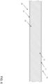
- Said compact inner layers 12 and 22 of said bodywork 10 and passenger compartment 20 walls are transformed to form the foamed inner layer 13 of said bodywork 10 wall and the foamed inner layer 23 of said passenger compartment 20 wall as illustrated in figure 4 .
- These layers are called foamed because they are formed of polymer cells forming gas pockets. Their thicknesses are greater than they had when they were compact. Their mechanical and physical properties are inferior to those they had when they were compact.
- the manufacturing process is the same as for making a standard two-layer part.
- Inner layer heating phase hot air (or any other gas) is injected into the part, between said foamed inner layer 13 of said body wall 10, and said foamed inner layer 23 of said passenger compartment wall 20.
- the air circulates between an entry point and an exit point in the part. These points can be said dropboxes 30 and/or said vents 31, and/or other points made specifically for this function.
- the temperature of the gas is higher than the decomposition temperature of the foaming agent. The temperature is high enough for the air in the bubbles located on the surface to expand and then for the bubbles to burst. There is then coalescence and a compact skin is thus formed on the foam layer.
- Said foamed inner layer 13 of said body wall 10 is thus transformed to form a compact inner layer 14 and a foamed middle layer 15.
- said foamed inner layer 23 of said passenger compartment wall 20 is thus transformed to form a compact inner layer 24 and a foamed middle layer 25.
- This structure is illustrated in figure 5 .
- This process produces a three-layer part (compact outer layer, foamed middle layer and compact inner layer) even though the part was rotomolded with only two layers of polymer.
- certain parts of said bodywork 01 are foamed until said foamed inner layer 13 and said foamed inner layer 23 join, as illustrated in the figure 6 .
- This can be achieved by a particular part design, i.e. a locally thinner part thickness which causes the foams to join together during the foaming phase.
- This can be achieved by locally increasing the thickness of the compact inner layers. There is thus locally a greater quantity of foaming agent, and therefore a greater foam thickness at the end of the foaming phase.
- This can be achieved by increasing the foaming temperature, for example locally outside the mold, so that the exothermic sublimation reaction of the foaming agent runs wild and results in a thicker (but therefore less compact) foam in the part.
- Merging said body wall 10 and said passenger compartment wall 20 can have several advantages. This makes it possible to stiffen the part locally, without resorting to the third layer (for example in areas in which the circulation of a flow of hot air is difficult to achieve). This can also make it possible to form preferential channels for the circulation of hot air during the heating phase of the inner layer.
- the side skirts 07, the windshield bottom 08 and the bumper 09 can be fully foamed as illustrated in FIG. figure 6 .
- FIG 10 illustrates a method of executing a "kiss-off" layer bonding pad 33 in a door.
- the base of the pad 33 is made in the layer 21 during the rotational molding thereof.
- the material bonding (illustrated by the reference 34) is made between 2 internal layers, one belonging to the bodywork wall 10, the other belonging to the passenger compartment wall 20.
- We then obtain considerably reinforced parts which meet the necessary resistance conditions.
- FIG. 11 to 13 illustrate methods of performing kiss off 33 at different locations on a body, these methods being illustrative and not limiting, such kiss offs being able to be placed at other locations as well.
- FIG 11 illustrates an exterior view in perspective and in section of a door with its external 10, internal 20 layers, the shape 35 of the layer 21 to create the kiss-off during rotational molding, and the layer re-bonding pad 33.
- Said kiss-off 33 creates a connection between the body wall 10 and the passenger compartment wall 20.
- the assembly will thus be much more difficult to deform because to deform one of the two walls, it will also be necessary to deform the other at the same time while these are linked by the material joint 34. In the event of a side impact, said door will therefore sink much less, ensuring better safety for the passengers.
- FIG 12 illustrates a perspective and sectional view of the interior of a door with its external 10 and internal 20 layers, the shape 35 of the layer 21 to create the kiss-off during rotational molding, and the layer re-bonding pad 33.
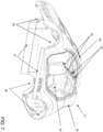
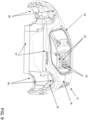
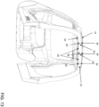
- FIG 13 illustrates a perspective rear view and a sectional view of the front of a body (as illustrated in the Figures 7 to 9 ) with its outer 10, inner 20 layers, the shape 35 of layer 21 to create the kiss-off during rotational molding, and the layer bonding pad 33.
- the kiss-offs are placed at roof level and make it possible to reinforce the structure at the seat belt anchor points (see the figure 7 to 9 ).
- Said kiss-off 33 makes a connection between the body wall 10 and the passenger compartment wall 20. The assembly will thus be much more difficult to deform because to deform one of the two walls, it will also be necessary to deform the other at the same time while these are linked by the material joint 34.
- said anchor points will resist the traction of said belts much better, ensuring better safety for the passengers.
Landscapes
- Engineering & Computer Science (AREA)
- Mechanical Engineering (AREA)
- Laminated Bodies (AREA)
- Vehicle Interior And Exterior Ornaments, Soundproofing, And Insulation (AREA)
Priority Applications (3)
| Application Number | Priority Date | Filing Date | Title |
|---|---|---|---|
| EP23184269.1A EP4488027A1 (de) | 2023-07-07 | 2023-07-07 | Verstärkte rundläuferkarosserie |
| PCT/IB2024/056378 WO2025012732A1 (fr) | 2023-07-07 | 2024-06-29 | Carrosserie rotomoulée renforcée |
| CN202480045856.2A CN121464026A (zh) | 2023-07-07 | 2024-06-29 | 增强滚塑车身 |
Applications Claiming Priority (1)
| Application Number | Priority Date | Filing Date | Title |
|---|---|---|---|
| EP23184269.1A EP4488027A1 (de) | 2023-07-07 | 2023-07-07 | Verstärkte rundläuferkarosserie |
Publications (1)
| Publication Number | Publication Date |
|---|---|
| EP4488027A1 true EP4488027A1 (de) | 2025-01-08 |
Family
ID=87196398
Family Applications (1)
| Application Number | Title | Priority Date | Filing Date |
|---|---|---|---|
| EP23184269.1A Withdrawn EP4488027A1 (de) | 2023-07-07 | 2023-07-07 | Verstärkte rundläuferkarosserie |
Country Status (3)
| Country | Link |
|---|---|
| EP (1) | EP4488027A1 (de) |
| CN (1) | CN121464026A (de) |
| WO (1) | WO2025012732A1 (de) |
Families Citing this family (1)
| Publication number | Priority date | Publication date | Assignee | Title |
|---|---|---|---|---|
| CN117642302A (zh) | 2021-07-05 | 2024-03-01 | 软车股份公司 | 车门 |
Citations (11)
| Publication number | Priority date | Publication date | Assignee | Title |
|---|---|---|---|---|
| US3875275A (en) * | 1958-05-05 | 1975-04-01 | Jerome H Lemelson | Method for molding composite bodies |
| JPH11129264A (ja) * | 1997-10-29 | 1999-05-18 | Nippon Zeon Co Ltd | 回転成形用金型、回転成形装置および反応性重合成形方法 |
| US6180203B1 (en) * | 1997-04-09 | 2001-01-30 | Peter J. Unkles | Rotational moulding process |
| US6261490B1 (en) * | 1998-09-15 | 2001-07-17 | Rotec Chemicals Limited | Rotational moulding |
| US20070063381A1 (en) * | 2004-03-19 | 2007-03-22 | Henry Stevens | Load-carrying apparatus and methods of manufacture |
| US7582238B1 (en) * | 2004-01-09 | 2009-09-01 | Yomazzo Michael J | Surfboard |
| EP2123419A1 (de) * | 2008-05-21 | 2009-11-25 | Total Petrochemicals Research Feluy | Freizeitboote aus Polyethylen-Schaum |
| US7785506B2 (en) * | 2002-09-27 | 2010-08-31 | Commissariat A L'energie Atomique | Method for rotational moulding of a workpiece comprising a thermoplastic foam layer |
| US20140220282A1 (en) * | 2011-09-09 | 2014-08-07 | Total Research & Technology Feluy | Rotomolded Articles Comprising a Layer of Polyolefin and Polyester |
| US20170334178A1 (en) * | 2013-03-05 | 2017-11-23 | Total Research & Technology Feluy | Multilayered Rotomoulded Articles |
| WO2021239883A2 (en) * | 2020-05-28 | 2021-12-02 | Total Research & Technology Feluy | Process for producing skin/foam/skin structure with high surface finish |
Family Cites Families (1)
| Publication number | Priority date | Publication date | Assignee | Title |
|---|---|---|---|---|
| US8690226B2 (en) * | 2010-09-21 | 2014-04-08 | Tata Technologies Pte Limited | Cost-effective, lightweight, thermoplastic automotive body structure manufactured by single step roto-molding process |
-
2023
- 2023-07-07 EP EP23184269.1A patent/EP4488027A1/de not_active Withdrawn
-
2024
- 2024-06-29 WO PCT/IB2024/056378 patent/WO2025012732A1/fr active Pending
- 2024-06-29 CN CN202480045856.2A patent/CN121464026A/zh active Pending
Patent Citations (11)
| Publication number | Priority date | Publication date | Assignee | Title |
|---|---|---|---|---|
| US3875275A (en) * | 1958-05-05 | 1975-04-01 | Jerome H Lemelson | Method for molding composite bodies |
| US6180203B1 (en) * | 1997-04-09 | 2001-01-30 | Peter J. Unkles | Rotational moulding process |
| JPH11129264A (ja) * | 1997-10-29 | 1999-05-18 | Nippon Zeon Co Ltd | 回転成形用金型、回転成形装置および反応性重合成形方法 |
| US6261490B1 (en) * | 1998-09-15 | 2001-07-17 | Rotec Chemicals Limited | Rotational moulding |
| US7785506B2 (en) * | 2002-09-27 | 2010-08-31 | Commissariat A L'energie Atomique | Method for rotational moulding of a workpiece comprising a thermoplastic foam layer |
| US7582238B1 (en) * | 2004-01-09 | 2009-09-01 | Yomazzo Michael J | Surfboard |
| US20070063381A1 (en) * | 2004-03-19 | 2007-03-22 | Henry Stevens | Load-carrying apparatus and methods of manufacture |
| EP2123419A1 (de) * | 2008-05-21 | 2009-11-25 | Total Petrochemicals Research Feluy | Freizeitboote aus Polyethylen-Schaum |
| US20140220282A1 (en) * | 2011-09-09 | 2014-08-07 | Total Research & Technology Feluy | Rotomolded Articles Comprising a Layer of Polyolefin and Polyester |
| US20170334178A1 (en) * | 2013-03-05 | 2017-11-23 | Total Research & Technology Feluy | Multilayered Rotomoulded Articles |
| WO2021239883A2 (en) * | 2020-05-28 | 2021-12-02 | Total Research & Technology Feluy | Process for producing skin/foam/skin structure with high surface finish |
Also Published As
| Publication number | Publication date |
|---|---|
| CN121464026A (zh) | 2026-02-03 |
| WO2025012732A1 (fr) | 2025-01-16 |
Similar Documents
| Publication | Publication Date | Title |
|---|---|---|
| Othman et al. | Application of carbon fiber reinforced plastics in automotive industry: A review | |
| FR2774352A1 (fr) | Element de renfort composite tridimensionnel pour vehicule automobile | |
| EP2431259B1 (de) | Kosteneffektive, leichtgewichtige, thermoplastische, mittels Einzelschritt-Rotationsformverfahren hergestellte Karosseriestruktur | |
| KR102191809B1 (ko) | 라미네이트 제조 방법, 에너지 흡수 장치, 에너지 흡수 장치 조성물 및 성형 도구 | |
| US6805542B2 (en) | Tool for forming a multiple foam substrate for impact energy absorption | |
| WO2025012732A1 (fr) | Carrosserie rotomoulée renforcée | |
| US6379595B1 (en) | Multiple density interior trim substrate and method of making same | |
| US20220220587A1 (en) | Aluminum alloys and structures | |
| EP3744622B1 (de) | Aufbau eines fahrzeugs | |
| EP3393889B1 (de) | Fahrzeugarchitektur | |
| Cischino et al. | An advanced technological lightweighted solution for a body in white | |
| US12365965B2 (en) | Al—Mg—Si based near-eutectic alloy composition for high strength and stiffness applications | |
| WO2001020189A1 (fr) | Element d'absorption des chocs, element interieur d'automobile et garniture de portiere automobile | |
| ITMI20071639A1 (it) | Metodo di produzione di un autoveicolo ed autoveicolo cosi ottenuto | |
| US20140044926A1 (en) | Plastic panels for motor vehicles and methods for making the same | |
| US7159931B2 (en) | Automotive roof rack and accessories manufactured with QPF/SPF technology | |
| US20100270846A1 (en) | Seating | |
| US12233941B2 (en) | Body structure for vehicle having reinforcement member | |
| US7682141B2 (en) | Production apparatus for forming plastic molded articles | |
| CN221251445U (zh) | 一种应用于乘用车的一体化铸铝门环结构 | |
| EP1718515A1 (de) | Verfahren zur herstellung eines eine synthetische materialschicht umfassenden fahrzeugbodens | |
| CN109476047B (zh) | 制造机动车的构件复合件的方法、构件复合件以及机动车 | |
| FR3014401A1 (fr) | Tablier avant par assemblage de pieces composites | |
| FR2683763A1 (fr) | Procede d'obtention par moulage de pieces, pretes a l'emploi, en materiaux composites. | |
| Urban et al. | Advanced automotive body structures and closures |
Legal Events
| Date | Code | Title | Description |
|---|---|---|---|
| PUAI | Public reference made under article 153(3) epc to a published international application that has entered the european phase |
Free format text: ORIGINAL CODE: 0009012 |
|
| STAA | Information on the status of an ep patent application or granted ep patent |
Free format text: STATUS: THE APPLICATION HAS BEEN PUBLISHED |
|
| AK | Designated contracting states |
Kind code of ref document: A1 Designated state(s): AL AT BE BG CH CY CZ DE DK EE ES FI FR GB GR HR HU IE IS IT LI LT LU LV MC ME MK MT NL NO PL PT RO RS SE SI SK SM TR |
|
| STAA | Information on the status of an ep patent application or granted ep patent |
Free format text: STATUS: THE APPLICATION IS DEEMED TO BE WITHDRAWN |
|
| 18D | Application deemed to be withdrawn |
Effective date: 20250709 |