EP4488037A1 - Verfahren und vorrichtung zur einstellung eines modellunterstützungspunktes, elektronische vorrichtung und lesbares speichermedium - Google Patents
Verfahren und vorrichtung zur einstellung eines modellunterstützungspunktes, elektronische vorrichtung und lesbares speichermedium Download PDFInfo
- Publication number
- EP4488037A1 EP4488037A1 EP22929656.1A EP22929656A EP4488037A1 EP 4488037 A1 EP4488037 A1 EP 4488037A1 EP 22929656 A EP22929656 A EP 22929656A EP 4488037 A1 EP4488037 A1 EP 4488037A1
- Authority
- EP
- European Patent Office
- Prior art keywords
- contour
- sharp corner
- overhang position
- corner area
- support point
- Prior art date
- Legal status (The legal status is an assumption and is not a legal conclusion. Google has not performed a legal analysis and makes no representation as to the accuracy of the status listed.)
- Pending
Links
Images


Classifications
-
- G—PHYSICS
- G06—COMPUTING OR CALCULATING; COUNTING
- G06F—ELECTRIC DIGITAL DATA PROCESSING
- G06F30/00—Computer-aided design [CAD]
- G06F30/20—Design optimisation, verification or simulation
-
- B—PERFORMING OPERATIONS; TRANSPORTING
- B29—WORKING OF PLASTICS; WORKING OF SUBSTANCES IN A PLASTIC STATE IN GENERAL
- B29C—SHAPING OR JOINING OF PLASTICS; SHAPING OF MATERIAL IN A PLASTIC STATE, NOT OTHERWISE PROVIDED FOR; AFTER-TREATMENT OF THE SHAPED PRODUCTS, e.g. REPAIRING
- B29C64/00—Additive manufacturing, i.e. manufacturing of three-dimensional [3D] objects by additive deposition, additive agglomeration or additive layering, e.g. by 3D printing, stereolithography or selective laser sintering
- B29C64/30—Auxiliary operations or equipment
- B29C64/386—Data acquisition or data processing for additive manufacturing
- B29C64/393—Data acquisition or data processing for additive manufacturing for controlling or regulating additive manufacturing processes
-
- B—PERFORMING OPERATIONS; TRANSPORTING
- B22—CASTING; POWDER METALLURGY
- B22F—WORKING METALLIC POWDER; MANUFACTURE OF ARTICLES FROM METALLIC POWDER; MAKING METALLIC POWDER; APPARATUS OR DEVICES SPECIALLY ADAPTED FOR METALLIC POWDER
- B22F10/00—Additive manufacturing of workpieces or articles from metallic powder
- B22F10/40—Structures for supporting workpieces or articles during manufacture and removed afterwards
-
- B—PERFORMING OPERATIONS; TRANSPORTING
- B22—CASTING; POWDER METALLURGY
- B22F—WORKING METALLIC POWDER; MANUFACTURE OF ARTICLES FROM METALLIC POWDER; MAKING METALLIC POWDER; APPARATUS OR DEVICES SPECIALLY ADAPTED FOR METALLIC POWDER
- B22F10/00—Additive manufacturing of workpieces or articles from metallic powder
- B22F10/80—Data acquisition or data processing
- B22F10/85—Data acquisition or data processing for controlling or regulating additive manufacturing processes
-
- B—PERFORMING OPERATIONS; TRANSPORTING
- B29—WORKING OF PLASTICS; WORKING OF SUBSTANCES IN A PLASTIC STATE IN GENERAL
- B29C—SHAPING OR JOINING OF PLASTICS; SHAPING OF MATERIAL IN A PLASTIC STATE, NOT OTHERWISE PROVIDED FOR; AFTER-TREATMENT OF THE SHAPED PRODUCTS, e.g. REPAIRING
- B29C64/00—Additive manufacturing, i.e. manufacturing of three-dimensional [3D] objects by additive deposition, additive agglomeration or additive layering, e.g. by 3D printing, stereolithography or selective laser sintering
- B29C64/20—Apparatus for additive manufacturing; Details thereof or accessories therefor
- B29C64/245—Platforms or substrates
-
- B—PERFORMING OPERATIONS; TRANSPORTING
- B29—WORKING OF PLASTICS; WORKING OF SUBSTANCES IN A PLASTIC STATE IN GENERAL
- B29C—SHAPING OR JOINING OF PLASTICS; SHAPING OF MATERIAL IN A PLASTIC STATE, NOT OTHERWISE PROVIDED FOR; AFTER-TREATMENT OF THE SHAPED PRODUCTS, e.g. REPAIRING
- B29C64/00—Additive manufacturing, i.e. manufacturing of three-dimensional [3D] objects by additive deposition, additive agglomeration or additive layering, e.g. by 3D printing, stereolithography or selective laser sintering
- B29C64/30—Auxiliary operations or equipment
- B29C64/386—Data acquisition or data processing for additive manufacturing
-
- B—PERFORMING OPERATIONS; TRANSPORTING
- B29—WORKING OF PLASTICS; WORKING OF SUBSTANCES IN A PLASTIC STATE IN GENERAL
- B29C—SHAPING OR JOINING OF PLASTICS; SHAPING OF MATERIAL IN A PLASTIC STATE, NOT OTHERWISE PROVIDED FOR; AFTER-TREATMENT OF THE SHAPED PRODUCTS, e.g. REPAIRING
- B29C64/00—Additive manufacturing, i.e. manufacturing of three-dimensional [3D] objects by additive deposition, additive agglomeration or additive layering, e.g. by 3D printing, stereolithography or selective laser sintering
- B29C64/40—Structures for supporting 3D objects during manufacture and intended to be sacrificed after completion thereof
-
- B—PERFORMING OPERATIONS; TRANSPORTING
- B33—ADDITIVE MANUFACTURING TECHNOLOGY
- B33Y—ADDITIVE MANUFACTURING, i.e. MANUFACTURING OF THREE-DIMENSIONAL [3D] OBJECTS BY ADDITIVE DEPOSITION, ADDITIVE AGGLOMERATION OR ADDITIVE LAYERING, e.g. BY 3D PRINTING, STEREOLITHOGRAPHY OR SELECTIVE LASER SINTERING
- B33Y50/00—Data acquisition or data processing for additive manufacturing
- B33Y50/02—Data acquisition or data processing for additive manufacturing for controlling or regulating additive manufacturing processes
-
- G—PHYSICS
- G06—COMPUTING OR CALCULATING; COUNTING
- G06F—ELECTRIC DIGITAL DATA PROCESSING
- G06F30/00—Computer-aided design [CAD]
- G06F30/10—Geometric CAD
- G06F30/17—Mechanical parametric or variational design
-
- G—PHYSICS
- G06—COMPUTING OR CALCULATING; COUNTING
- G06F—ELECTRIC DIGITAL DATA PROCESSING
- G06F2113/00—Details relating to the application field
- G06F2113/10—Additive manufacturing, e.g. three-dimensional [3D] printing
-
- Y—GENERAL TAGGING OF NEW TECHNOLOGICAL DEVELOPMENTS; GENERAL TAGGING OF CROSS-SECTIONAL TECHNOLOGIES SPANNING OVER SEVERAL SECTIONS OF THE IPC; TECHNICAL SUBJECTS COVERED BY FORMER USPC CROSS-REFERENCE ART COLLECTIONS [XRACs] AND DIGESTS
- Y02—TECHNOLOGIES OR APPLICATIONS FOR MITIGATION OR ADAPTATION AGAINST CLIMATE CHANGE
- Y02P—CLIMATE CHANGE MITIGATION TECHNOLOGIES IN THE PRODUCTION OR PROCESSING OF GOODS
- Y02P10/00—Technologies related to metal processing
- Y02P10/25—Process efficiency
-
- Y—GENERAL TAGGING OF NEW TECHNOLOGICAL DEVELOPMENTS; GENERAL TAGGING OF CROSS-SECTIONAL TECHNOLOGIES SPANNING OVER SEVERAL SECTIONS OF THE IPC; TECHNICAL SUBJECTS COVERED BY FORMER USPC CROSS-REFERENCE ART COLLECTIONS [XRACs] AND DIGESTS
- Y02—TECHNOLOGIES OR APPLICATIONS FOR MITIGATION OR ADAPTATION AGAINST CLIMATE CHANGE
- Y02T—CLIMATE CHANGE MITIGATION TECHNOLOGIES RELATED TO TRANSPORTATION
- Y02T90/00—Enabling technologies or technologies with a potential or indirect contribution to GHG emissions mitigation
Definitions
- This application relates to the field of three-dimensional (3D) printing technologies, and specifically, to a model support point setting method, a model support point setting device, an electronic device, and a computer readable storage medium.
- 3D printing is a cumulative manufacturing technology, also known as additive manufacturing.
- the 3D printing is a technology that uses bondable materials such as special waxes, powdered metals, or plastics to print 3D objects according to digital model files.
- this application provides a model support point setting method, a model support point setting device, an electronic device, and a computer readable storage medium, which is capable of setting support points on a sharp corner area that is easy to collapse of a model, to avoid a situation of a model printing failure due to absences of the support points on the sharp corner area.
- First aspect of this application provides a model support point setting method
- the model support point setting method includes: layering a model into a plurality of layers according to a preset layer height, and obtaining a contour of each of the plurality of layers; locating a suspended layer according to the contour of each of the plurality of layers, the model including a suspended part, and the suspended layer being the lowest layer of the suspended part; obtaining a suspension position of the suspended layer according to a contour of a lower layer of the suspended layer and a contour of the suspended layer; determining a contour of an overhang position according to the suspension position of the suspended layer, and determining a sharp corner area and a non-sharp corner area of the overhang position according to the contour of the overhang position; and setting support points on the sharp corner area and the non-sharp corner area of the overhang position according to preset support point densities corresponding to the sharp corner area and the non-sharp corner area of the overhang position.
- the overhang position of the model is divided into a sharp corner area and a non-sharp corner area, and the sharp corner area and the non-sharp corner area can correspond to different support point densities, so that support points can be set on the sharp corner area that is easy to collapse of the model, and the situation of the model printing failure due to absences of the support points on the sharp corner area can be avoided.
- the method of determining the contour of the overhang position according to the suspension position of the suspended layer includes: determining a first contour according to a safety offset value and the contour of the lower layer of the suspended layer; determining a second contour according to a tilt offset value and the first contour; and obtaining the contour of the overhang position by subtracting the first contour and the second contour with a contour of the suspension position of the suspended layer; or determining the first contour according to the safety offset value and the contour of the lower layer of the suspended layer; and obtaining the contour of the overhang position by subtracting the first contour with the contour of the suspension position of the suspended layer; or defining the contour of the suspension position of the suspended layer as the contour of the overhang position.
- the contour of the overhang layer can be divided into the first contour, the second contour and the contour of the overhang position, the overhang position is provided with support points, the first contour and the second contour can be provided with or not provided with support points, if the first contour and the second contour are not provided with support points, the number of support points of the model can be reduced, and a model printing speed can be improved.
- the model support point setting method further includes: setting the support points on an area where the first contour is located according to a preset support point density corresponding to the first contour; and setting the support points on an area where the second contour is located according to a preset support point density corresponding to the second contour.
- support points can be set on the first contour and the second contour, and the first contour and the second contour can have different densities of support points.
- the method of determining the sharp corner area of the overhang position according to the contour of the overhang position includes: lessening the contour of the overhang position to obtain a first intermediate contour according to the safety offset value; enlarging the first intermediate contour by the safety offset value to obtain a second intermediate contour according to a jtSquare parameter attribute; and determining the sharp corner area of the overhang position by subtracting the second intermediate contour with the contour of the overhang position.
- the contour of the overhang position can be lessened by the safety offset value to obtain the first intermediate contour, and the first intermediate contour can be enlarged by the safety offset value to obtain the second intermediate contour according to the jtSquare parameter attribute, and then the sharp corner area of the overhang position can be determined by subtracting the second intermediate contour with the contour of the overhang position.
- the non-sharp corner area of the overhang position includes two contour areas, the two contour areas respectively correspond to one preset support point density, and the two contour areas are determined by: subtracting the first intermediate contour with the second intermediate contour to obtain a third contour; and defining the first intermediate contour and the third contour as the two contour areas of the non-sharp corner area of the overhang position.
- the non-sharp corner area of the overhang position can be divided into two contour areas, and different support point densities or the same support point densities can be set for the two contour areas of the non-sharp corner area to achieve model printing support.
- the method of determining the sharp corner area of the overhang position according to the contour of the overhang position includes: lessening the contour of the overhang position to obtain a first intermediate contour according to the safety offset value; subtracting the first intermediate contour with the contour of the overhang position to obtain a third intermediate contour; enlarging the third intermediate contour by the safety offset value to obtain a fourth intermediate contour according to a jtSquare parameter attribute; enlarging the third intermediate contour by the safety offset value to obtain a fifth intermediate contour according to a jtMiter parameter attribute; subtracting the fifth intermediate contour with the fourth intermediate contour to obtain a sixth intermediate contour; enlarging the sixth intermediate contour by a preset multiple to obtain a seventh intermediate contour; intersecting the seventh intermediate contour with the third intermediate contour are intersected to obtain the sharp corner area of the overhang position.
- the third intermediate contour and the seventh intermediate contour can be obtained according to the contour of the overhang position, the preset safety offset value, the jtSquare parameter attribute and the jtMiter parameter attribute, and then the sharp corner area of the overhang position can be determined by intersecting the seventh intermediate contour with the third intermediate contour.
- the non-sharp corner area of the overhang position includes two contour areas, the two contour areas respectively correspond to one preset support point density, and the two contour areas are determined by: subtracting the sharp corner area of the overhang position with the third intermediate contour to obtain a fourth contour; and defining the first intermediate contour and the fourth contour as the two contour areas of the non-sharp corner area of the overhang position.
- the non-sharp corner area of the overhang position can be divided into two contour areas, and different support point densities or the same support point densities can be set for the two contour areas of the non-sharp corner area to achieve model printing support.
- the method of setting the support points on each area according to corresponding preset support point density includes: sampling each area to obtain sampling points of each area by a random manner; setting the support points on the current area according to sampling points of the current area and a preset support point density corresponding to the current area; screening the support points on the current area to make a distance between any two support points is greater than or equal to a preset value.
- the sharp corner area of the model can be provided with support points, the non-sharp corner area and the sharp corner area can correspond to different support point densities, and the situation of the model printing failure due to absences of the support points on the sharp corner area can be avoided.
- the distance between any two support points can be greater than or equal to the preset value, the number of support points of the model can be reduced, and the printing speed of the model can be improved.
- the safety offset value when the preset safety angle and the layer height of the model are determined, the safety offset value can be calculated according to the first preset formula, and when the preset tilt angle and the layer height of the model are determined, the tilt offset value can be calculated according to the second preset formula.
- the model support point setting device includes: a layering module, configured to layer a model into a plurality of layers according to a preset layer height, and obtain a contour of each of the plurality of layers; a locating module, configured to locate a suspended layer according to the contour of each of the plurality of layers, the model including a suspended part, and the suspended layer being the lowest layer of the suspended part; a first processing module, configured to obtain a suspension position of the suspended layer according to a contour of a lower layer of the suspended layer and a contour of the suspended layer; a second processing module, configured to determine a contour of an overhang position according to the suspension position of the suspended layer, and determine a sharp corner area and a non-sharp corner area of the overhang position according to the contour of the overhang position; and a setting module, configured to set support points on the sharp corner area and the non-sharp corner area of the overhang position according to preset support point densities corresponding to the sharp corner
- the overhang position of the model is divided into a sharp corner area and a non-sharp corner area, and the sharp corner area and the non-sharp corner area can correspond to different support point densities, so that support points can be set on the sharp corner area that is easy to collapse of the model, and the situation of the model printing failure due to absences of the support points on the sharp corner area can be avoided.
- Third aspect of this application provides an electronic device, the electronic device includes: a processor; and a storage medium configured to store instructions. When the instructions run on the processor, to cause the electronic device to execute the model support point setting method.
- Fourth aspect of this application provides a computer readable storage medium, the computer readable storage medium stores computer instructions, when the computer instructions run on an electronic device, the electronic device is caused to execute the model support point setting method.
- This application provides a model support point setting method, the model support point setting method includes: layering a model into a plurality of layers according to a preset layer height, and obtaining a contour of each of the plurality of layers; locating a suspended layer according to the contour of each of the plurality of layers, the model including a suspended part, and the suspended layer being the lowest layer of the suspended part; obtaining a suspension position of the suspended layer according to a contour of a lower layer of the suspended layer and a contour of the suspended layer; determining a contour of an overhang position according to the suspension position of the suspended layer, and determining a sharp corner area and a non-sharp corner area of the overhang position according to the contour of the overhang position; and setting support points on the sharp corner area and the non-sharp corner area of the overhang position according to preset support point densities corresponding to the sharp corner area and the non-sharp corner area of the overhang position.
- the model support point setting method obtains the contour of the overhang position of the model and divides the overhang position into a sharp corner area and a non-sharp corner area.
- the sharp corner area and the non-sharp corner area can correspond to different support point densities, support points can be set on the sharp corner area that is easy to collapse of the model, and the situation of the model printing failure due to absences of the support points on the sharp corner area can be avoided.
- the model support point setting method of the present application can be applied to a 3D printer or an electronic device.
- the electronic device can be a device that can automatically perform numerical calculations and/or information processing according to pre-set or stored instructions, and hardware of the electronic device can include but is not limited to microprocessors, application-specific integrated circuits (ASICs), field-programmable gate arrays (FPGAs), and digital signal processors (DSPs), embedded devices, etc.
- the electronic device can be computing devices, such as desktop computers, laptops, servers, industrial computers, etc.
- the electronic device can interact with a user through keyboards, mice, remote controls, touchpads, or voice-activated devices.
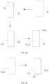
- FIG. 1 is a flowchart of a model support point setting method according to an embodiment of the present application.
- a sequence of blocks in the flowchart can be changed and some blocks can be omitted according to different requirements, the model support point setting method may include the following blocks.
- a model is layered into a plurality of layers according to a preset layer height, and a contour of each of the plurality of layers is obtained.
- the model can be built according to contour parameters of an object to be printed, and the object to be printed can be selected according to actual printing requirements, and the application does not limit this.
- the model of the object to be printed can be designed through a model design software, such as a computer aided design (CAD) software.
- the model can be layered by a slice/layering software, which can be the current slice/layering software, such as Magics software.
- a height of the model M1 is 16.4 cm and the layer height of the model M1 set by a user is 0.05 cm, and the model M1 can be divided into 328 layers (16.4/0.05).
- the contour of each layer of the model M1 can be obtained.
- a suspended layer is located according to the contour of each of the plurality of layers.
- a phenomenon of printing materials falling during the process of model printing can be avoided by adding support points to the model, and a success rate of model printing can be improved.
- the model includes a suspended part, printing materials falling during an accumulation at the suspended part can be avoided by adding supports for the suspended part.
- the overhang layer can be located by traversing the contour of each of the plurality of layers.
- the model M1 includes the suspended part M11, the suspended layer can be the lowest layer of the suspended part M11.
- L i represents a contour of the suspended layer of the model M1
- L i-1 represents a contour of the lower layer of the suspended layer
- L i+1 represents a contour of the upper layer of the suspended layer.
- a suspension position of the suspended layer is obtained according to the contour of the lower layer of the suspended layer and the contour of the suspended layer.
- the suspension position of the suspended layer when the suspended layer is determined, can be obtained n accordance with the contour of the lower layer of the suspended layer and the contour of the suspended layer.
- the suspension position of the suspended layer can be a difference area between the contour of the suspended layer and the contour of the lower layer of the suspended layer.
- the suspension position of the suspended layer can by obtained by subtracting the contour of the suspended layer with the contour of the lower layer of the suspended layer.
- a contour of an overhang position is determined according to the suspension position of the suspended layer, and a sharp corner area and a non-sharp corner area of the overhang position are determined according to the contour of the overhang position.
- the suspension position can be divided into three types of areas: a safety area, a tilt area, and the overhang position.
- the safety area can be a part of the suspension position, and no support points need to be set on the safety area.
- the tilt area can be a part of the suspension position, and few support points need to be set on the tilt area.
- the overhang position can be an area in the suspension position except the safety area and the tilt area, and more support points need to be set on the overhang position than the tilt area. For example, when the safety area and the tilt area of the suspension position are determined, the contour of the overhang position can be obtained by subtracting the contour of the suspension position with the contour of the safety area and the contour of the tilt area.
- the suspension position can also be directly defined as the overhang position, that is, divisions of the safety area and the tilt area are omitted, and all areas of the suspension position are taken as the overhang position.
- the suspension position can also be divided into the overhang position and the safety area according to whether or not setting support points. That is, the tilt area is classified as the overhang position. For example, when the safe area of the suspension position is determined, the contour of the overhang position can be obtained by subtracting the contour of the suspension position with the contour of the safety area.
- the safety area can be determined according to the contour of the lower layer of the suspended layer, a preset safety angle, and the preset layer height, and the tilt area can be determined according to the contour of the safety area, a preset tilt angle and the preset layer height.
- the preset safety angle and the preset tilt angle can be set by the user before model printing, values of the preset safety angle and the preset tilt angle can be set and adjusted according to actual printing requirements, and this application is not limited to this.
- the preset safety angle can represent a suspension part that is cooled and formed within this angle does not need to set support points.
- the preset tilt angle can represent a suspension part that is cooled and formed within this angle need to set few support points.
- the preset safety angle A1 is 35 degrees and the preset tilt angle A2 is 75 degrees.
- the safety offset value offset_1 can be calculated according to the preset safety angle A1 and the layer height h
- the tilt offset value offset_2 can be calculated according to the preset tilt angle A2 and the layer height h.
- the safe offset value offset_1 can be calculated according to a first preset formula
- the safety offset value offset_1 and the tilt offset value offset_2 can also be set by the user before model printing, that is, it is not necessary to calculate the safety offset value offset_1 and the tilt offset value offset_2 according to the first preset formula and the second preset formula.
- the contour L i-1 of the lower layer of the suspended layer can be offset along a first direction according to the safety offset value offset_1, and a first offset contour Q1 can be obtained.
- the first contour P1 can be obtained by subtracting the first offset contour Q1 with the contour L i-1 of the lower layer of the suspended layer, the first contour P1 may be the safety area of the suspension position.
- the first direction may be an extension direction of the contour L i-1 of the lower layer of the suspended layer.
- the contour L i-1 of the lower layer of the suspended layer is offset along the first direction by the safety offset value offset_1 to obtain the first offset contour Q1 according to a offset function of a Clipper library, and the first contour P1 can be obtained by subtracting the first offset contour Q1 with the contour L i-1 of the lower layer of the suspended layer.
- the first contour P1 can be offset along the first direction by the tilt offset value offset_2 to obtain the second offset contour Q2, and the second contour P2 can be obtained by subtracting the second intermediate contour O2 with the first contour P1, the second contour P2 may be the tilt area of the suspension position.
- the first contour P1 is offset along the first direction by the tilt offset value offset_2 to obtain the second offset contour Q2 according to the offset function of the Clipper library, and the second contour P2 can be obtained by subtracting the second offset contour Q2 with the first contour P1.
- the suspension position is divided into the overhang position, the safety area (a area included in the contour profile P1), and the tilt area (a area included in the second contour P2) as an example, when the first contour P1 and the second contour P2 are obtained, the contour of the overhang position can be obtained by subtracting the contour of the suspension position with the first contour P1 and the second contour P2. As shown in FIG. 4C , the contour P t of the overhang position is obtained by subtracting the contour P d of the suspension position with the first contour P1 and the second contour P2.
- the overhang position can be divided into one or more sharp corner areas and one or more non-sharp corner areas.
- the non-sharp corner areas can be areas in the overhang position except the sharp corner areas.
- the sharp corner area SA1 and the non-sharp corner area SA2 of the overhang position can be determined by following manners: a1). lessening the contour P t of the overhang position to obtain a first intermediate contour O1 according to the safety offset value offset_1, for example, the contour P t of the overhang position is quadrilateral, and four sides of the contour P t of the overhang position are lessened along a center point direction of the contour P t by the safety offset value offset_1 to obtain the first intermediate contour O1; a2).
- four sharp corner areas SA1 of the overhang position can be obtained according to the above manners a1 to a3.
- the non-sharp corner area SA2 of the overhang position may include two contour areas, each of the two contour areas may respectively correspond a preset support point density, for example, the two contour areas can correspond to different preset support point densities.
- the sharp corner area SA1 and the non-sharp corner area SA2 of the overhang position are determined according to a manner as shown in FIG.
- the two contour regions of the non-sharp corner area SA2 can be determined by following manners: subtracting the second intermediate contour O2 with the first intermediate contour O1 to obtain a third contour P3; and defining the first intermediate contour O1 and the third contour P3 as the two contour areas of the non-sharp corner area SA2 of the overhang position.
- the sharp corner area SA1 and the non-sharp corner area SA2 of the overhang position can be determined according to the contour P t of the overhang position under following manners: b1). lessening the contour P t of the overhang position to obtain the first intermediate contour O1 according to the safety offset value offset_1; b2). subtracting the first intermediate contour O1 with the contour P t of the overhang position to obtain a third intermediate contour O3; b3). enlarging the third intermediate contour O3 by the safety offset value offset_1 to obtain a fourth intermediate contour O4 according to a jtSquare parameter attribute of the Clipper library; b4).
- the non-sharp corner area SA2 of the overhang position may include two contour areas, each of the two contour areas may respectively correspond a preset support point density, for example, the two contour areas can correspond to different preset support point densities.
- the sharp corner area SA1 and the non-sharp corner area SA2 of the overhang position are determined according to a manner as shown in FIG.
- the two contour regions of the non-sharp corner area SA2 can be determined by following manners: subtracting the third intermediate contour O3 with the sharp corner area SA1 to obtain a fourth contour P4; and defining the first intermediate contour O1 and the fourth contour P4 as the two contour areas of the non-sharp corner area SA2 of the overhang position.
- the preset multiple can be set according to actual requirements, for example, the preset multiple is set to 1.5-3.
- support points are set on the sharp corner area and the non-sharp corner area of the overhang position according to preset support point densities corresponding to the sharp corner area and the non-sharp corner area of the overhang position.
- the support points are can be respectively set on the sharp corner area SA1 and the non-sharp corner area SA2 of the overhang position according to corresponding preset support point densities.
- the sharp corner area SA1 and the non-sharp corner area SA2 of the overhang position can correspond to different preset support point densities.
- support points can also be set on a area where the first contour P1 is located according to a corresponding preset support point density of the first contour P1, and the support points can also be set on a area where the second contour P2 is located according to a corresponding preset support point density of the second contour P2.
- the preset support point densities corresponding to the first contour P1 and the second contour P2 can be set according to actual printing requirements.
- a support point density corresponding to the first contour P1 is less than a support point density corresponding to the second contour P2
- the support point density corresponding to the second contour P2 is less than a support point density corresponding to the non-sharp corner area of the overhang position.
- support points can be set for each area according to corresponding preset support point densities under following manners: c1). dividing the current area that need to be provided with support points into a plurality of triangles, and sampling the plurality of triangles to obtain sampling points by a random manner; c2). setting the support points on the current area according to sampling points of the current area and a preset support point density corresponding to the current area; c3). screening the support points on the current area to make a distance between any two support points on the current area is greater than or equal to a preset value. By screening the support points, the number of support points on each area can meet a printing support requirement of the model M1, the printing speed of the model can be improved, and printing materials can also be saved.
- the support points when screening the support points, it preferentially set support points on the sharp corner area SA1 of the overhang position, to ensure support points being set one the sharp corner area SA1.
- a Poisson sampling algorithm can be used to randomly sample points in the triangles to obtain the sampling points.
- the preset value can also be set according to actual requirements, and this application is not limited to this, for example, the preset value can be set to 1cm.
- the model M1 can be sliced to obtain a geometric code (Gcode) file, and the 3D printer can print the model M1 including supports according to the Gcode file, and the model M1 can be obtained by removing the supports.
- Gcode geometric code
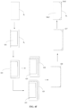
- FIG. 5 is a schematic structural diagram of a model support point setting device according to an embodiment of the present application.
- the model support point setting device 10 can be applied to an electronic device.
- the model support point setting device 10 may include one or more modules.
- the model support point setting device 10 may include a layering module 101, a locating module 102, a first processing module 103, a second processing module 104, and a setting module 105.
- model support point setting device 10 may include some or all of functional modules shown in FIG. 5 corresponding to each embodiment in the above-mentioned model support point setting method, and a function of each module 101-105 is specifically described as below. It should be noted that the same nouns, the related nouns, and the specific explanations in embodiments of the above-mentioned model support point setting method can also be applied to functional introductions for each module 101-105. For a sake of space and repetition, it's not described in this embodiment.
- the layering module 101 is configured to layer a model into a plurality of layers according to a preset layer height, and obtain a contour of each of the plurality of layers.
- the locating module 102 is configured to locate a suspended layer according to the contour of each of the plurality of layers, the model includes a suspended part, and the suspended layer is the lowest layer of the suspended part.
- the first processing module 103 is configured to obtain a suspension position of the suspended layer according to a contour of a lower layer of the suspended layer and a contour of the suspended layer.
- the second processing module 104 is configured to determine a contour of an overhang position according to the suspension position of the suspended layer, and determine a sharp corner area and a non-sharp corner area of the overhang position according to the contour of the overhang position.
- the setting module 105 is configured to set support points on the sharp corner area and the non-sharp corner area of the overhang position according to preset support point densities corresponding to the sharp corner area and the non-sharp corner area of the overhang position.
- FIG. 6 is a schematic structural diagram of a 3D printer according to an embodiment of the present application.
- the 3D printer 300 may include a main controller 1001, an extruder module 1002, a motor 1003 and a control display module 1004.
- the main controller 1001 can execute programs or instructions to control the motor 1003 and the control display module 1004 to display information, communicate with other subassemblies, etc.
- the extruder module 1002 may include an extruder, a heating rod, etc., which can realize a heating and extrusion of printing materials.
- the control display module 1004 may include buttons, touch displays, etc., and can allow users to input control instructions, display a use situation of the 3D printer 100 and a printing progress, etc.
- a first computer program 42 can be stored in a flash memory of the main controller 1001, and the main controller 1001 can execute the first computer program 42 to achieve printing the model M1 including the supports according to a Gcode file.
- the first computer program 42 may also be divided into one or more modules/units, and one or more modules/units are stored in the flash memory of the main controller 1001 and executed by the main controller 1001 to complete one or more technical scheme of the present application.
- the one or more modules/units may be a series of computer program instruction segments capable of completing a specific function, and the instruction segments are used for describing a execution process of the first computer program 42 in the 3D printer 100.
- the main controller 1001 can be a microprocessor, a single-chip microcomputer, etc.
- the schematic diagram is only an example of the 3D printer 100 and does not form a limitation to the 3D printer 100, and the 3D printer 100 may include more or fewer components than illustrated, or combine some components, or different components, such as the 3D printer 100 may further include communication modules, etc.
- FIG. 7 is a schematic structural diagram of an electronic device according to an embodiment of the present application.
- the electronic device 200 may a storage medium 20, a processor 30 and a second computer program 44 stored in the storage medium 20 and can run on the processor 30.
- the processor 30 executes the second computer program 44, blocks in the embodiments of the model support point setting method can be realized, such as blocks S11-S15 shown in FIG. 1 .
- the second computer program 44 may also be divided into one or more modules/units, and the one or more modules/units are stored in storage medium 20 and executed by the processor 30.
- the one or more modules/units may be a series of computer program instruction segments capable of completing a specific function, and the instruction segments are used for describing a execution process of the second computer program 44 in the electronic device 200.
- the second computer program 44 can be divided into the layering module 101, the locating module 102, the first processing module 103, the second processing module 104, and the setting module 105 as shown in FIG. 5 .
- the electronic device 200 can be desktop computers, notebooks, handheld computers, industrial computers, tablet computers, servers and other computing devices.
- the skilled in the art can understand that the schematic diagram is only an example of the electronic device 200 and does not form a limitation to the electronic device 200, and the electronic device 200 may include more or fewer components than illustrated, or combine some components, or different components, such as the electronic device 200 may further include input and output devices, network access devices, buses, etc.
- the processor 30 can be a central processing unit (CPU), or other general-purpose processors, digital signal processors (DSPs), application-specific integrated circuits (ASICs), field-programmable gate arrays (FPGAs), or other programmable logic devices, discrete gates or transistor logic devices, discrete hardware components, etc.
- the general-purpose processors can be microprocessors, single chips.
- the processor 30 also can be other conventional processors, etc.
- the storage medium 20 can be used to store the second computer program 44 and/or modules/units, and the processor 30 realizes various functions of the electronic device 200 by running or executing computer programs and/or modules/units stored in storage medium 20 and calling data stored in the storage medium 20.
- the storage medium 20 may include a program storing area and a data storing area, the program storing area can store an operating system, applications required for at least one function (such as a sound playback function, a image playback function, etc.), and the data storing area can store data (for example audio data) that is created according to a use of the electronic device 200.
- the storage medium 20 may include high-speed random access memory and non-volatile memory, such as hard disks, memory, pluggable hard drives, smart media cards (SMCs), secure digital (SD) cards, Flash cards, at least one disk storage device, flash memory devices, or other non-volatile solid-state storage devices.
- non-volatile memory such as hard disks, memory, pluggable hard drives, smart media cards (SMCs), secure digital (SD) cards, Flash cards, at least one disk storage device, flash memory devices, or other non-volatile solid-state storage devices.
- the modules/units integrated in the electronic device 200 can be stored in a computer-readable storage medium if implemented in a form of software functional units and marketed or used as a stand-alone product. Under this manner, all or part of processes of the method of the embodiments of the present application can be completed by instructing relevant hardware through a computer program, the computer program can be stored in a computer readable storage medium, and the computer program can realize the blocks of the embodiment of each method when it is executed by the processor.
- the computer program may include computer program code, and the computer program code may be in a form of source codes, object codes, executable files, or some intermediate forms, etc.
- the computer readable medium may include any entity or device capable of carrying the computer program code, such as a recording medium, a USB flash drive, a mobile hard disk, a magnetic disk, an optical disc, a computer memory, a read-only memory (ROM), a random access memory (RAM), an electric carrier signal, a telecommunication signal, and a software distribution medium.
- a recording medium such as a USB flash drive, a mobile hard disk, a magnetic disk, an optical disc, a computer memory, a read-only memory (ROM), a random access memory (RAM), an electric carrier signal, a telecommunication signal, and a software distribution medium.
- ROM read-only memory
- RAM random access memory
- the electronic devices and methods may be realized by other manners.
- the embodiment of the electronic device described above is only schematic, for example, the division of the units/modules is only a logical function division, and it may exist another division manner when it is actually realized.
- each functional unit in each embodiment of the present application may be integrated in the same processing unit, or each unit may separately exist, or two or more units may be integrated in the same unit.
- the above-mentioned integrated unit can be realized in a form of hardware or in a form of hardware plus software function module.
Landscapes
- Engineering & Computer Science (AREA)
- Chemical & Material Sciences (AREA)
- Materials Engineering (AREA)
- Manufacturing & Machinery (AREA)
- Physics & Mathematics (AREA)
- Optics & Photonics (AREA)
- Mechanical Engineering (AREA)
- Theoretical Computer Science (AREA)
- Geometry (AREA)
- General Physics & Mathematics (AREA)
- Computer Hardware Design (AREA)
- General Engineering & Computer Science (AREA)
- Evolutionary Computation (AREA)
- Computational Mathematics (AREA)
- Pure & Applied Mathematics (AREA)
- Mathematical Optimization (AREA)
- Mathematical Analysis (AREA)
- Processing Or Creating Images (AREA)
Applications Claiming Priority (2)
| Application Number | Priority Date | Filing Date | Title |
|---|---|---|---|
| CN202210194013.1A CN114559660B (zh) | 2022-03-01 | 2022-03-01 | 模型支撑点设置方法、装置、电子设备及可读存储介质 |
| PCT/CN2022/141716 WO2023165232A1 (zh) | 2022-03-01 | 2022-12-24 | 模型支撑点设置方法、装置、电子设备及可读存储介质 |
Publications (2)
| Publication Number | Publication Date |
|---|---|
| EP4488037A1 true EP4488037A1 (de) | 2025-01-08 |
| EP4488037A4 EP4488037A4 (de) | 2026-03-04 |
Family
ID=81716210
Family Applications (1)
| Application Number | Title | Priority Date | Filing Date |
|---|---|---|---|
| EP22929656.1A Pending EP4488037A4 (de) | 2022-03-01 | 2022-12-24 | Verfahren und vorrichtung zur einstellung eines modellunterstützungspunktes, elektronische vorrichtung und lesbares speichermedium |
Country Status (4)
| Country | Link |
|---|---|
| US (1) | US20250026079A1 (de) |
| EP (1) | EP4488037A4 (de) |
| CN (1) | CN114559660B (de) |
| WO (1) | WO2023165232A1 (de) |
Families Citing this family (2)
| Publication number | Priority date | Publication date | Assignee | Title |
|---|---|---|---|---|
| CN114559660B (zh) * | 2022-03-01 | 2023-06-30 | 深圳市创想三维科技股份有限公司 | 模型支撑点设置方法、装置、电子设备及可读存储介质 |
| CN119427752B (zh) * | 2023-07-28 | 2025-10-24 | 广东汉邦激光科技有限公司 | 基于3d打印的支撑区域识别方法、电子设备及存储介质 |
Family Cites Families (20)
| Publication number | Priority date | Publication date | Assignee | Title |
|---|---|---|---|---|
| GB0719747D0 (en) * | 2007-10-10 | 2007-11-21 | Materialise Nv | Method and apparatus for automatic support generation for an object made by means of a rapid prototype production method |
| US8983643B2 (en) * | 2010-01-15 | 2015-03-17 | Stratasys, Inc. | Method for generating and building support structures with deposition-based digital manufacturing systems |
| DE102013011630B4 (de) * | 2013-07-12 | 2021-09-02 | Delcam, Ltd. | Verfahren zum Berechnen von Stützstrukturen |
| CN107053651B (zh) * | 2016-02-05 | 2019-07-12 | 三纬国际立体列印科技股份有限公司 | 三维模型打印切层方法 |
| EP3442772A4 (de) * | 2016-04-14 | 2019-11-13 | Desktop Metal, Inc. | Generative fertigung mit stützstrukturen |
| CN105904729B (zh) * | 2016-04-22 | 2018-04-06 | 浙江大学 | 一种基于倾斜分层的无支撑三维打印方法 |
| EP4008526A1 (de) * | 2016-11-25 | 2022-06-08 | Dassault Systèmes | Ausrichtung eines realen objekts zum 3d-drucken |
| US10775770B2 (en) * | 2017-06-22 | 2020-09-15 | Autodesk, Inc. | Building and attaching support structures for 3D printing |
| US11584065B2 (en) * | 2018-01-23 | 2023-02-21 | Rapidflight Holdings, Llc | Additively manufactured structure and method for making the same |
| US20200004225A1 (en) * | 2018-06-29 | 2020-01-02 | Velo3D, Inc. | Manipulating one or more formation variables to form three-dimensional objects |
| CN110893686A (zh) * | 2018-08-24 | 2020-03-20 | 三纬国际立体列印科技股份有限公司 | 立体打印方法以及立体打印装置 |
| TWI659867B (zh) * | 2018-08-24 | 2019-05-21 | 三緯國際立體列印科技股份有限公司 | 立體列印方法以及立體列印裝置 |
| KR102099014B1 (ko) * | 2018-08-30 | 2020-04-08 | 전자부품연구원 | 3d 프린팅을 위한 2d 슬라이싱 폴리라인 기반 서포트 구조 생성 방법 |
| CN112861201B (zh) * | 2021-01-21 | 2022-04-05 | 浙江大学 | 一种基于支撑点膨胀融合的3d打印支撑区域生成方法 |
| CN113313747B (zh) * | 2021-05-25 | 2022-07-08 | 华中科技大学鄂州工业技术研究院 | 一种基于stl格式的三维模型支撑点获取方法 |
| CN113370526B (zh) * | 2021-06-03 | 2024-02-02 | 深圳市创必得科技有限公司 | 切片预处理3d模型悬空检测方法 |
| CN113414412B (zh) * | 2021-06-25 | 2023-05-30 | 上海埃曼增材技术有限公司 | 一种面向增材制造悬垂结构的支撑点确定方法 |
| CN113580577B (zh) * | 2021-07-29 | 2024-03-15 | 深圳市创想三维科技股份有限公司 | 3d打印文件生成方法、装置、计算机设备和存储介质 |
| CN114013045B (zh) * | 2021-10-28 | 2023-12-05 | 深圳市创想三维科技股份有限公司 | 3d打印文件的生成方法、装置、计算机设备及存储介质 |
| CN114559660B (zh) * | 2022-03-01 | 2023-06-30 | 深圳市创想三维科技股份有限公司 | 模型支撑点设置方法、装置、电子设备及可读存储介质 |
-
2022
- 2022-03-01 CN CN202210194013.1A patent/CN114559660B/zh active Active
- 2022-12-24 US US18/714,201 patent/US20250026079A1/en active Pending
- 2022-12-24 EP EP22929656.1A patent/EP4488037A4/de active Pending
- 2022-12-24 WO PCT/CN2022/141716 patent/WO2023165232A1/zh not_active Ceased
Also Published As
| Publication number | Publication date |
|---|---|
| CN114559660B (zh) | 2023-06-30 |
| WO2023165232A1 (zh) | 2023-09-07 |
| US20250026079A1 (en) | 2025-01-23 |
| EP4488037A4 (de) | 2026-03-04 |
| CN114559660A (zh) | 2022-05-31 |
Similar Documents
| Publication | Publication Date | Title |
|---|---|---|
| EP4488037A1 (de) | Verfahren und vorrichtung zur einstellung eines modellunterstützungspunktes, elektronische vorrichtung und lesbares speichermedium | |
| US20230409812A1 (en) | Formatting document objects by visual suggestions | |
| US12069209B2 (en) | Information processing apparatus, information processing method, and storage medium that determine whether a current value of a non-position attribute value on which an operation of changing is being performed is within a predefined range | |
| US11340755B2 (en) | Moving a position of interest on a display | |
| CN112765695B (zh) | 支撑体生成方法、3d打印机、计算机装置及存储介质 | |
| EP4092512A1 (de) | Dynamisches elementsteuerungsverfahren, elektronische vorrichtung sowie computerlesbares speichermedium | |
| CN112765108A (zh) | 一种文档加载方法、计算设备及可读存储介质 | |
| CN118617748A (zh) | 光固化3d打印的交错式分层填充优化方法、装置及设备 | |
| CN114240973A (zh) | 图纸分割方法、设备及存储介质 | |
| CN121245001B (zh) | 晶格化支撑的优化方法及系统、计算机设备、介质及计算机程序产品 | |
| CN118012317B (zh) | 一种编程工具缩放方法以及相关装置 | |
| Ghazanfari et al. | Adaptive rastering algorithm for freeform extrusion fabrication processes | |
| CN115087936A (zh) | 确定车床的切削样式的方法、控制设备以及车床 | |
| CN114417617A (zh) | 嵌套字模型生成方法、装置、电子设备及可读存储介质 | |
| EP4058290B1 (de) | Verfahren und vorrichtung zum entwurf und zur herstellung eines bauteils in einer rechnergestützten design- und herstellungsumgebung | |
| CN118627147B (zh) | 露天矿山采掘带三维设计方法、装置、设备、介质和产品 | |
| CN114160811A (zh) | 材料成型加工方法、装置、设备及存储介质 | |
| JP2026506765A (ja) | 3d印刷方法、装置、3d印刷機及びコンピュータ機器 | |
| US9744756B2 (en) | Method, apparatus and computer readable medium for producing prototype diagram of three dimensional object | |
| JP2024048138A (ja) | プログラム、情報処理装置、及び情報処理方法 | |
| CN116521025A (zh) | 输入法候选词窗口的移动方法和装置 | |
| CN120297220A (zh) | 布局方法、装置、电子设备及存储介质 | |
| CN117112939A (zh) | 一种图标布局方法、装置、计算设备及存储介质 | |
| CN120973504A (zh) | 中断事件处理方法、设备、存储介质及程序产品 | |
| CN118832858A (zh) | 摆放3d模型的方法及系统、计算机设备及存储介质 |
Legal Events
| Date | Code | Title | Description |
|---|---|---|---|
| STAA | Information on the status of an ep patent application or granted ep patent |
Free format text: STATUS: THE INTERNATIONAL PUBLICATION HAS BEEN MADE |
|
| PUAI | Public reference made under article 153(3) epc to a published international application that has entered the european phase |
Free format text: ORIGINAL CODE: 0009012 |
|
| STAA | Information on the status of an ep patent application or granted ep patent |
Free format text: STATUS: REQUEST FOR EXAMINATION WAS MADE |
|
| 17P | Request for examination filed |
Effective date: 20240718 |
|
| AK | Designated contracting states |
Kind code of ref document: A1 Designated state(s): AL AT BE BG CH CY CZ DE DK EE ES FI FR GB GR HR HU IE IS IT LI LT LU LV MC ME MK MT NL NO PL PT RO RS SE SI SK SM TR |
|
| DAV | Request for validation of the european patent (deleted) | ||
| DAX | Request for extension of the european patent (deleted) | ||
| A4 | Supplementary search report drawn up and despatched |
Effective date: 20260130 |
|
| RIC1 | Information provided on ipc code assigned before grant |
Ipc: B29C 64/386 20170101AFI20260126BHEP Ipc: G06F 30/20 20200101ALI20260126BHEP Ipc: B22F 10/40 20210101ALI20260126BHEP Ipc: B22F 10/80 20210101ALI20260126BHEP Ipc: B29C 64/40 20170101ALI20260126BHEP Ipc: B29C 64/393 20170101ALI20260126BHEP Ipc: B33Y 50/02 20150101ALI20260126BHEP Ipc: B33Y 50/00 20150101ALI20260126BHEP Ipc: G06F 30/17 20200101ALI20260126BHEP Ipc: G06F 113/10 20200101ALN20260126BHEP |