EP4488045A2 - Procédé de calandrage d'une bande d'électrodes et dispositif de calandrage - Google Patents
Procédé de calandrage d'une bande d'électrodes et dispositif de calandrage Download PDFInfo
- Publication number
- EP4488045A2 EP4488045A2 EP24183298.9A EP24183298A EP4488045A2 EP 4488045 A2 EP4488045 A2 EP 4488045A2 EP 24183298 A EP24183298 A EP 24183298A EP 4488045 A2 EP4488045 A2 EP 4488045A2
- Authority
- EP
- European Patent Office
- Prior art keywords
- defect
- control
- electrode strip
- calendering
- roller pair
- Prior art date
- Legal status (The legal status is an assumption and is not a legal conclusion. Google has not performed a legal analysis and makes no representation as to the accuracy of the status listed.)
- Pending
Links
Images


Classifications
-
- B—PERFORMING OPERATIONS; TRANSPORTING
- B30—PRESSES
- B30B—PRESSES IN GENERAL
- B30B3/00—Presses characterised by the use of rotary pressing members, e.g. rollers, rings, discs
- B30B3/04—Presses characterised by the use of rotary pressing members, e.g. rollers, rings, discs co-operating with one another, e.g. with co-operating cones
-
- B—PERFORMING OPERATIONS; TRANSPORTING
- B29—WORKING OF PLASTICS; WORKING OF SUBSTANCES IN A PLASTIC STATE IN GENERAL
- B29C—SHAPING OR JOINING OF PLASTICS; SHAPING OF MATERIAL IN A PLASTIC STATE, NOT OTHERWISE PROVIDED FOR; AFTER-TREATMENT OF THE SHAPED PRODUCTS, e.g. REPAIRING
- B29C43/00—Compression moulding, i.e. applying external pressure to flow the moulding material; Apparatus therefor
- B29C43/22—Compression moulding, i.e. applying external pressure to flow the moulding material; Apparatus therefor of articles of indefinite length
- B29C43/24—Calendering
- B29C43/245—Adjusting calender parameters, e.g. bank quantity
-
- B—PERFORMING OPERATIONS; TRANSPORTING
- B30—PRESSES
- B30B—PRESSES IN GENERAL
- B30B11/00—Presses specially adapted for forming shaped articles from material in particulate or plastic state, e.g. briquetting presses, tabletting presses
- B30B11/005—Control arrangements
- B30B11/006—Control arrangements for roller presses
-
- B—PERFORMING OPERATIONS; TRANSPORTING
- B30—PRESSES
- B30B—PRESSES IN GENERAL
- B30B15/00—Details of, or accessories for, presses; Auxiliary measures in connection with pressing
-
- B—PERFORMING OPERATIONS; TRANSPORTING
- B30—PRESSES
- B30B—PRESSES IN GENERAL
- B30B15/00—Details of, or accessories for, presses; Auxiliary measures in connection with pressing
- B30B15/26—Program-control arrangements
-
- B—PERFORMING OPERATIONS; TRANSPORTING
- B30—PRESSES
- B30B—PRESSES IN GENERAL
- B30B15/00—Details of, or accessories for, presses; Auxiliary measures in connection with pressing
- B30B15/28—Arrangements for preventing distortion of, or damage to, presses or parts thereof
-
- B—PERFORMING OPERATIONS; TRANSPORTING
- B30—PRESSES
- B30B—PRESSES IN GENERAL
- B30B15/00—Details of, or accessories for, presses; Auxiliary measures in connection with pressing
- B30B15/30—Feeding material to presses
-
- G—PHYSICS
- G01—MEASURING; TESTING
- G01N—INVESTIGATING OR ANALYSING MATERIALS BY DETERMINING THEIR CHEMICAL OR PHYSICAL PROPERTIES
- G01N21/00—Investigating or analysing materials by the use of optical means, i.e. using sub-millimetre waves, infrared, visible or ultraviolet light
- G01N21/84—Systems specially adapted for particular applications
- G01N21/86—Investigating moving sheets
-
- G—PHYSICS
- G01—MEASURING; TESTING
- G01N—INVESTIGATING OR ANALYSING MATERIALS BY DETERMINING THEIR CHEMICAL OR PHYSICAL PROPERTIES
- G01N21/00—Investigating or analysing materials by the use of optical means, i.e. using sub-millimetre waves, infrared, visible or ultraviolet light
- G01N21/84—Systems specially adapted for particular applications
- G01N21/88—Investigating the presence of flaws or contamination
- G01N21/8851—Scan or image signal processing specially adapted therefor, e.g. for scan signal adjustment, for detecting different kinds of defects, for compensating for structures, markings, edges
-
- H—ELECTRICITY
- H01—ELECTRIC ELEMENTS
- H01M—PROCESSES OR MEANS, e.g. BATTERIES, FOR THE DIRECT CONVERSION OF CHEMICAL ENERGY INTO ELECTRICAL ENERGY
- H01M10/00—Secondary cells; Manufacture thereof
- H01M10/04—Construction or manufacture in general
- H01M10/0404—Machines for assembling batteries
-
- H—ELECTRICITY
- H01—ELECTRIC ELEMENTS
- H01M—PROCESSES OR MEANS, e.g. BATTERIES, FOR THE DIRECT CONVERSION OF CHEMICAL ENERGY INTO ELECTRICAL ENERGY
- H01M4/00—Electrodes
- H01M4/02—Electrodes composed of, or comprising, active material
- H01M4/04—Processes of manufacture in general
- H01M4/043—Processes of manufacture in general involving compressing or compaction
- H01M4/0435—Rolling or calendering
-
- B—PERFORMING OPERATIONS; TRANSPORTING
- B29—WORKING OF PLASTICS; WORKING OF SUBSTANCES IN A PLASTIC STATE IN GENERAL
- B29C—SHAPING OR JOINING OF PLASTICS; SHAPING OF MATERIAL IN A PLASTIC STATE, NOT OTHERWISE PROVIDED FOR; AFTER-TREATMENT OF THE SHAPED PRODUCTS, e.g. REPAIRING
- B29C43/00—Compression moulding, i.e. applying external pressure to flow the moulding material; Apparatus therefor
- B29C43/32—Component parts, details or accessories; Auxiliary operations
- B29C43/58—Measuring, controlling or regulating
- B29C2043/585—Measuring, controlling or regulating detecting defects, e.g. foreign matter between the moulds, inaccurate position, breakage
-
- B—PERFORMING OPERATIONS; TRANSPORTING
- B29—WORKING OF PLASTICS; WORKING OF SUBSTANCES IN A PLASTIC STATE IN GENERAL
- B29C—SHAPING OR JOINING OF PLASTICS; SHAPING OF MATERIAL IN A PLASTIC STATE, NOT OTHERWISE PROVIDED FOR; AFTER-TREATMENT OF THE SHAPED PRODUCTS, e.g. REPAIRING
- B29C43/00—Compression moulding, i.e. applying external pressure to flow the moulding material; Apparatus therefor
- B29C43/32—Component parts, details or accessories; Auxiliary operations
- B29C43/58—Measuring, controlling or regulating
- B29C2043/5875—Measuring, controlling or regulating the material feed to the moulds or mould parts, e.g. controlling feed flow, velocity, weight, doses
-
- B—PERFORMING OPERATIONS; TRANSPORTING
- B29—WORKING OF PLASTICS; WORKING OF SUBSTANCES IN A PLASTIC STATE IN GENERAL
- B29C—SHAPING OR JOINING OF PLASTICS; SHAPING OF MATERIAL IN A PLASTIC STATE, NOT OTHERWISE PROVIDED FOR; AFTER-TREATMENT OF THE SHAPED PRODUCTS, e.g. REPAIRING
- B29C43/00—Compression moulding, i.e. applying external pressure to flow the moulding material; Apparatus therefor
- B29C43/32—Component parts, details or accessories; Auxiliary operations
- B29C43/58—Measuring, controlling or regulating
- B29C2043/5891—Measuring, controlling or regulating using imaging devices, e.g. cameras
-
- B—PERFORMING OPERATIONS; TRANSPORTING
- B29—WORKING OF PLASTICS; WORKING OF SUBSTANCES IN A PLASTIC STATE IN GENERAL
- B29L—INDEXING SCHEME ASSOCIATED WITH SUBCLASS B29C, RELATING TO PARTICULAR ARTICLES
- B29L2031/00—Other particular articles
- B29L2031/34—Electrical apparatus, e.g. sparking plugs or parts thereof
- B29L2031/3468—Batteries, accumulators or fuel cells
-
- G—PHYSICS
- G01—MEASURING; TESTING
- G01N—INVESTIGATING OR ANALYSING MATERIALS BY DETERMINING THEIR CHEMICAL OR PHYSICAL PROPERTIES
- G01N21/00—Investigating or analysing materials by the use of optical means, i.e. using sub-millimetre waves, infrared, visible or ultraviolet light
- G01N21/84—Systems specially adapted for particular applications
- G01N21/86—Investigating moving sheets
- G01N2021/8654—Mechanical support; Mounting of sheet
-
- G—PHYSICS
- G01—MEASURING; TESTING
- G01N—INVESTIGATING OR ANALYSING MATERIALS BY DETERMINING THEIR CHEMICAL OR PHYSICAL PROPERTIES
- G01N21/00—Investigating or analysing materials by the use of optical means, i.e. using sub-millimetre waves, infrared, visible or ultraviolet light
- G01N21/84—Systems specially adapted for particular applications
- G01N21/88—Investigating the presence of flaws or contamination
- G01N21/8851—Scan or image signal processing specially adapted therefor, e.g. for scan signal adjustment, for detecting different kinds of defects, for compensating for structures, markings, edges
- G01N2021/8854—Grading and classifying of flaws
- G01N2021/888—Marking defects
Definitions
- the invention relates to a method for calendering an electrode strip according to the preamble of claim 1 and to a calendering device according to claim 10.
- a calendering process is carried out in which an electrode strip is guided through a roller gap of a roller pair of a calendering device. As it is guided through, the electrode strip is compressed under very high roller pressure between solid steel rollers of the roller pair.
- the electrode strip can have defects due to production, such as a splice connection or surface defects on the electrode strip. If these defects are guided through the roller gap without further precautions, the high roller pressure can cause considerable damage to the roller pair. To prevent such damage, the calendering process has so far been monitored manually by a worker.
- the worker If the worker detects a defect, the worker interrupts the calendering process, adjusts the roller pair from a calendering position to an open position, guides the defect through the roller gap, adjusts the roller pair to the calendering position and starts the calendering process again.
- a roller press machine, a control and/or regulation system of a roller press machine and a control and/or regulation method of a roller press machine are known.
- a leading edge of a workpiece is detected by means of a position sensor before the leading edge enters a roller gap of the roller press machine.
- the object of the invention is to provide a method for calendering an electrode strip, with which a higher overall equipment efficiency can be achieved compared to the known method.
- a further object is to provide a To provide a calendering device with which the process for calendering an electrode strip can be carried out cost-efficiently.
- a method for calendering an electrode strip with a calendering process in which an electrode strip is guided through a roller gap of a roller pair of a calendering device, specifically with compression of the electrode strip, in which calendering process a defect detection step is carried out in which at least one defect in the electrode strip is directly or indirectly detected, and in which calendering process, if a defect is detected in the defect detection step, the roller pair is adjusted in an opening step from a calendering position of the roller pair to an open position of the roller pair, specifically before the defect reaches the roller gap.
- the defect detection step and/or the opening step is carried out, preferably automatically or fully automatically, by means of a control and/or regulating system of the calendering device.
- the defect detection step and/or the opening step carried out by the control and/or regulation system means that neither manual monitoring of the process nor manual interruptions are necessary.
- the automatic opening step ensures that the defect can be guided through the roller gap without interfering contours and thus without damaging the roller pair.
- indirect detection of the defect is understood to mean that the defect and/or the position of the defect is recognized by means of a marking, preferably by means of a marking, preferably by means of a color marking.
- direct detection of the defect is understood to mean that the defect and/or the position of the defect is recognized and/or detected by means of a sensor, preferably by means of a CCD sensor, directly and/or by means of the defect itself.
- the roller gap in the calendering position of the roller pair the roller gap has a calendering gap width and/or that in the open position of the roller pair the roller gap has a defect gap width.
- the defect is categorized in the defect detection step, whereby the defect is categorized either as endangering the roll or as not endangering the roll. If a defect that is not endangering the roll is detected, no opening step and/or no closing step is carried out and the calendering process continues unchanged. The calendering process is therefore not interrupted or slowed down for every defect, but only for a defect that is endangering the roll. The overall system effectiveness in the method therefore advantageously depends only on defects that are also endangering the roll.
- the control and/or regulating system has a data memory, and that data memory position information about the position of the defect in the electrode strip, preferably in relation to the electrode strip and/or a longitudinal direction of the electrode strip, is stored in the data memory, and that a control and/or regulating unit of the control and/or regulating system retrieves and/or receives the data memory position information, preferably in the defect detection step and/or for detecting the defect, as a data memory signal.
- the data memory position information represents a digital marking that can be used, for example, to reduce a strip speed of the electrode strip prematurely, preferably before a physical marking, for example in the form of a color marking, is recognized, preferably detected, by the control and/or regulating system.
- the control and/or regulating system has a sensor and that the position of the defect in the electrode strip, preferably in relation to the electrode strip and/or a longitudinal direction of the electrode strip, is recognized, preferably detected, by means of the sensor, and that sensor position information about the position of the defect is transmitted as a sensor signal from the sensor to the control and/or regulating unit of the control and/or regulating system in the defect recognition step.
- the sensor position information represents position information that is redundant to the data storage position information. This has the advantage that the reliability of the defect detection is significantly increased.
- the senor is formed by a color sensor or a CCD sensor, and that a marking, preferably a color marking, is preferably applied on or parallel to the at least one defect, and that the position of the defect of the electrode strip, preferably in relation to the Electrode strip and/or a longitudinal direction of the electrode strip is recognized, preferably detected, by means of the color sensor or the CCD sensor based on the marking, preferably color marking, applied to the defect.
- the color marking represents a physical marking. Compared to general sensory detection, for example, the color marking has the advantage that the color marking can be detected in a simple manner and, above all, with particularly high process reliability.
- the position of the at least one defect is detected directly by the CCD sensor, preferably in a surface inspection process, wherein it can preferably be provided that the position of the defect is recognized and/or detected not via a marking or color marking, but directly and/or based on the defect itself and/or without a previously applied marking by means of the CCD sensor.
- the at least one defect is recognized and/or detected by the CCD sensor, preferably directly and/or immediately before the roller gap.
- the marking is preferably formed by the adhesive tape at least at the defects where an adhesive tape is at least partially exposed.
- This has the advantage that no separate marking, preferably color marking, or no additional adhesive sticker is required on a splice connection in order to mark the splice connection as a defect. Instead, the defect in the form of the splice connection is recognized and/or detected directly based on the adhesive tape and/or its color.
- the adhesive tape can therefore preferably have the same color as the color marking or an adhesive sticker forming the color marking.
- the control and/or regulating system has an unwinding splicing device, and that the position of the defect in the electrode strip, preferably in relation to the electrode strip and/or a longitudinal direction of the electrode strip, is recognized, preferably detected, by means of the unwinding splicing device, and that splice position information about the position of the defect in the defect detection step is transmitted as a splice signal from the unwinding splicing device to the control and/or regulating unit of the control and/or regulating system. Additionally or alternatively, position information can therefore also be determined via the unwinding splicing device. The process reliability in defect detection is thereby further increased in comparison to defect detection based only on the data storage and/or sensor position information.
- the data storage position information is formed by the splice position information.
- the splice position information can also be stored as data storage position information in the data storage.
- the splice position information is transmitted to the data storage as a splice signal and stored there. This has the advantage that there does not necessarily have to be a direct signal connection between the unwinding splicing device and the control and/or regulating unit.
- the control and/or regulating system has the control and/or regulating unit, and that the data storage position information is transmitted as a data storage signal and/or the sensor position information as a sensor signal and/or the splice position information as a splice signal to the control and/or regulating unit and, preferably, the signals are processed in the control and/or regulating unit to form control information, and that the control information is transmitted as an opening signal to an actuator of the control and/or regulating system, and that the actuator is controlled in the opening step by means of the opening signal in such a way that the pair of rollers is adjusted by means of the actuator from the calendering position to the open position.
- the position information is therefore further processed in the control and/or regulating unit depending on availability.
- the position information can advantageously be compared with one another and the accuracy of the position determination of the defect can thereby be increased.
- the actuator is controlled by the control and/or regulating unit using the control signal in such a way that the roller pair is adjusted to the open position before the at least one defect reaches the roller gap, and/or that the actuator is controlled by the control and/or regulating unit using the control signal in such a way that the roller pair is adjusted to the open position after a defect-carrying strip section of the electrode strip has reached the roller gap.
- the actuator enables the roller gap to be adjusted particularly cost-effectively.
- the defect-preparing strip section of the electrode strip is directly adjacent to the defect and/or reaches the roll gap before the defect.
- the defect-containing lead belt section is uncompacted or not completely compacted after passing through the roller gap.
- the defect leading strip section preferably viewed in the running direction and/or parallel to the running direction, has a leading strip section length, and that the amount of the leading strip section length, preferably at a strip speed of the electrode strip in a range of 25 m/min to 150 m/min, is in a range of 5 cm to 150 cm, preferably in a range of 10 cm to 30 cm, particularly preferably 20 cm.
- the lead strip length of 20 cm represents a good compromise between low waste of the electrode strip and ensuring that no damage occurs to the roller pair.
- a web speed of the electrode strip is reduced by means of the control and/or regulating system from a calendering strip speed to a defect strip speed before the defect reaches the roll gap.
- the web speed of the electrode strip is reduced by means of the control and/or regulating system from the calendering strip speed to the defect strip speed after the defect leading strip section has reached the roll gap.
- the method has a closing step, and that in the closing step the control and/or regulating unit generates a closing signal and transmits it to the actuator, and that the actuator is controlled in the closing step by means of the closing signal such that the roller pair is adjusted from the open position to the calendering position by means of the actuator, wherein it can preferably be provided that the actuator is controlled by the control and/or regulating unit by means of the closing signal such that the roller pair is adjusted to the calendering position as soon as a defect trailing belt section of the electrode belt has left the roller gap, and/or wherein it can preferably be provided that the actuator is controlled by the control and/or regulating unit by means of the closing signal in such a way that the pair of rollers is adjusted from the open position to the calendering position after the at least one defect has left the roller gap.
- the closing step enables the calendering process to be continued automatically after the defect has passed through the roller gap. The duration of the interruptions is therefore reduced to a minimum
- the closing step is carried out, preferably automatically or fully automatically, by means of the control and/or regulation system of the calendering device.
- the method can thus be carried out fully automatically.
- the defect-following belt section of the electrode belt directly adjoins the defect and/or reaches the roll gap after the defect.
- the defect trailing belt section is uncompacted or not completely compacted after passing through the roller gap.
- the defect trailing belt section of the electrode belt has a trailing belt section length, and that the amount of the trailing belt section length is in a range from 5 cm to 150 cm, preferably in a range from 10 cm to 30 cm, particularly preferably 20 cm.
- the trailing belt section length of 20 cm represents a good compromise between low rejects of the electrode belt and ensuring that no damage occurs to the roller pair.
- a web speed of the electrode strip is reduced to zero by means of the control and/or regulating system before the start and/or before the end of the closing step, preferably from the calendering strip speed or from the defect strip speed, wherein it can preferably be provided that the electrode strip is increased from zero to the calendering web speed by means of the control and/or regulating system after the end of the closing step.
- a calendering device is also proposed, preferably for carrying out a method as described above, with a pair of rollers through which an electrode strip is passed in a calendering process, preferably in an endless process, under Compaction of the electrode strip, and a control and/or regulating system.
- the control and/or regulating system is suitable and/or designed to carry out a defect detection step in the calendering process, preferably automatically or fully automatically, and to detect at least one defect on the electrode strip directly or indirectly.
- the control and/or regulating system is suitable and/or designed to adjust the roller pair, when a defect is detected, preferably automatically or fully automatically, from a calendering position of the roller pair, in which the roller gap preferably has a calendering gap width, to an open position of the roller pair, in which the roller gap preferably has a defect gap width.
- the electrode strip has a carrier element and at least one coating.
- the carrier element is formed by a carrier film, wherein it can preferably be provided that the carrier film exclusively or at least partially comprises aluminum and/or copper.
- the coating comprises active material and/or binder.
- the designations upper and lower roller are not to be understood as spatial direction specifications, but that the lower roller can only be referred to as a first roller, preferably arranged in some way, and the upper roller can only be referred to as a second roller, preferably arranged in some way.
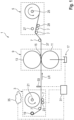
- a calendering device 1 is shown.
- the calendering device 1 has an unwinding unit 3 and a winding unit 5.
- the calendering device 1 also has guide rollers 7 and a pair of rollers 9.
- the pair of rollers 9 has a lower roller 11 formed by a cylindrical metal roller and an upper roller 13 formed by a cylindrical metal roller.
- the lower roller 11 is connected to an actuator 17 of the calendering device 1, here for example to a hydraulic actuator.
- the actuator 17 as an electromechanical actuator, for example.
- the calendering device 1 has a control and/or regulating system.
- the control and/or regulating system has a control and/or regulating unit 31, a sensor 33, the actuator 17, the unwinding splicing device 23 and a data storage device 35, which is designed here merely as an example as a cloud storage device.
- the sensor 33 is formed, here merely as an example, by a color sensor.
- the control and/or regulating unit 31 is in signal connection with the sensor 33 and is in signal connection with the data memory 35. Furthermore, the control and/or regulating unit 31 in signal connection with the actuator 17. The control and/or regulating unit 31 is also in signal connection with the unwinding splicing device 23.
- the signal connections are in the Figure 1 using the lines emanating from the control and/or regulating unit 31, preferably dash-dot lines.
- a roller gap 15 is provided between the lower roller 11 and the upper roller 13.
- the lower roller 11 limits the roller gap 15 downwards and the upper roller 13 limits the roller gap 15 upwards.
- the roller gap 15 has an adjustable gap width.
- the gap width can be adjusted by adjusting the lower roller 11 by means of the actuator 17 controlled by the control and/or regulating unit 31 from a calendering gap width, in which the roller pair 9 is in a calendering position, to a defect gap width, in which the roller pair 9 is in an open position, and vice versa.
- the amount of the calendering gap width is less than the amount of a strip thickness D of the electrode strip 37 in the uncalendered state, as shown in Figure 2
- the amount of the gap width of the defects is preferably larger than one in which Figure 2 shown, defect thickness FD of a, in the Figure 2 enlarged, defect 39.
- the defect 39 is in the Figure 2 formed merely by way of example by a splice connection.
- the electrode strip 37 of different electrode coils is connected to one another by means of the splice connection, namely by interposing a double-sided adhesive tape 41 between one end of the electrode strip 37 of a first electrode coil arranged on the first unwinding core 19 and one end of the electrode strip 37 of a second electrode coil arranged on the second unwinding core 21.
- the defect thickness FD results from adding twice the strip thickness D of the electrode strip 37 and a thickness KD of the adhesive tape 41.
- the defect 39 can also be formed, for example, by a surface defect and/or by a material agglomerate and/or by a bubble.
- the calendering device 1 is designed and suitable for compacting the electrode strip 37 from an uncalendered state into a calendered state in one process.
- the electrode strip 37 has a carrier layer (not shown), for example formed by an aluminum or copper-containing carrier foil, and a coating (not shown) which, for example, has an active material and, for example, a binding agent.
- the porosity may be too high, which is reduced to an optimum by calendering and/or compacting.
- the Electrode strip 37 in the calendered and/or compacted state is further processed to produce electrodes for, for example, lithium-ion batteries and enables higher energy densities compared to electrodes made from electrode strip in the uncalendered state.
- the electrode strip 37 also has the defect 39 here merely as an example. If the roller gap 15 is set to the calendering gap width and the electrode strip 37 with the defect 39 is guided through the roller gap 15, the roller pair 9 is damaged.
- the damage can consist in at least the lower roller 11 or at least the upper roller 13 being deformed, or in both the lower roller 11 and the upper roller 13 being deformed.
- the defect 39 is formed by different types of splice connections.
- a strip of the adhesive tape 41 is applied to an upper side of the splice connection between the electrode tape 37 and a strip of the adhesive tape 41 is applied to an underside of the splice connection between the electrode tape 37.
- the adhesive tape 41 is exposed and can be detected by the sensor 33, preferably by the color sensor. Since the adhesive tape 41 is exposed and is detected by the sensor 33, preferably the color sensor, the adhesive tape 41 fulfills a double function in addition to connecting the electrode tape of the two electrode coils, namely in that the adhesive tape 41 additionally has a detectable by means of the sensor 33 Marking of the splice connection and thus of the defect 39.
- a defect detection step is carried out fully automatically by means of the control and/or regulating system, in which the defect 39 is detected.
- the roller pair 9 is adjusted fully automatically by the control and/or regulating system in an opening step from the calendering position of the roller pair 9 to the open position of the roller pair 9 before the defect 39 reaches the roller gap 15.
- the defect 39 is recognized, preferably detected, in the defect recognition step by means of digital recognition and/or physical recognition.
- data storage position information about the position of the defect 39 is stored in the data storage 35.
- the data storage position information is retrieved and received by the control and/or regulating unit 31 of the control and/or regulating system as a data storage signal.
- the data storage position information about the position of the defect 39 can, for example, be stored in the data storage beforehand manually by a worker or preferably by an automatic surface inspection by, for example, a camera system with a CCD sensor. This can be done, for example, in a coating and/or slitting process for producing the electrode strip 37.
- the surface inspection in a process step preceding the calendering is useful in order to detect the defects as soon as possible after their to detect defects at their onset so that if an unexpectedly high number of defects occur, measures can be taken immediately.
- the position of the defect 39 is detected by means of the sensor 33 formed by the color sensor.
- a color marking is applied to the defect 39 or parallel to the defect 39 at a defined location on the electrode strip 37, preferably at the edge of the electrode strip 37 or even with a projection beyond the edge of the electrode strip 37, which color marking is in the Figures 2 and 3 is shown merely as an example as an adhesive sticker 42.
- the color marking or the adhesive sticker 42 are purely optional.
- the color marking in this or in an embodiment of the method can of course also be formed, for example, by applying paint.
- the adhesive sticker can, for example, be applied manually in advance by a worker and/or by an automatic surface inspection using, for example, a camera system with a CCD sensor and an automatic defect marking system on the defect 39 or parallel to the defect 39 at a defined point on the electrode strip 37, preferably on the edge of the electrode strip 37. This can be done, for example, in a coating and/or slitting process for producing the electrode strip 37.
- the surface inspection in a process step preceding calendering is useful in order to detect the defects as soon as possible after they occur, so that measures can be initiated immediately if an unexpectedly high number of defects occur.
- the defect leading strip section 43 of the electrode strip 37 directly adjoins the defect 39 and reaches the roller gap 15, seen in the running direction LR, before, in particular in time before, the defect 39.
- the defect-free leading belt section 43 is uncompacted or partially compacted after passing through the roller gap 15.
- the defect-free leading belt section 43 has, preferably viewed in the running direction LR and/or parallel to the running direction LR, a leading belt section length of only 20 cm by way of example.
- the defect-following belt section 45 of the electrode belt 37 is directly adjacent to the defect 39 and passes and/or reaches the roller gap 15 only after the defect 39.
- the defect-following belt section 45 is uncompacted after passing through the roller gap 15, preferably only partially compacted, as shown in the Figure 3 is shown.
- the defect trailing band section 45 of the electrode band 37 has a trailing band section length. For example only, the length of the trailing band section is 20 cm.
- the belt speed of the electrode belt 37 is reduced from the defect belt speed to zero by means of the control and/or regulating system and the electrode belt 37 is thus stopped. This is intended to prevent the electrode belt 37 from tearing when the roller gap 15 is closed.
- the belt speed of the electrode belt 37 is then increased from zero back to the calendering belt speed.
Landscapes
- Engineering & Computer Science (AREA)
- Mechanical Engineering (AREA)
- Chemical & Material Sciences (AREA)
- Manufacturing & Machinery (AREA)
- Chemical Kinetics & Catalysis (AREA)
- Electrochemistry (AREA)
- General Chemical & Material Sciences (AREA)
- Health & Medical Sciences (AREA)
- Physics & Mathematics (AREA)
- Life Sciences & Earth Sciences (AREA)
- Analytical Chemistry (AREA)
- Biochemistry (AREA)
- General Health & Medical Sciences (AREA)
- General Physics & Mathematics (AREA)
- Immunology (AREA)
- Pathology (AREA)
- Signal Processing (AREA)
- Computer Vision & Pattern Recognition (AREA)
- Battery Electrode And Active Subsutance (AREA)
- Controlling Sheets Or Webs (AREA)
Applications Claiming Priority (1)
| Application Number | Priority Date | Filing Date | Title |
|---|---|---|---|
| DE102023206347.6A DE102023206347A1 (de) | 2023-07-04 | 2023-07-04 | Verfahren zum Kalandrieren eines Elektrodenbandes und Kalandriervorrichtung |
Publications (2)
| Publication Number | Publication Date |
|---|---|
| EP4488045A2 true EP4488045A2 (fr) | 2025-01-08 |
| EP4488045A3 EP4488045A3 (fr) | 2025-04-30 |
Family
ID=91620925
Family Applications (1)
| Application Number | Title | Priority Date | Filing Date |
|---|---|---|---|
| EP24183298.9A Pending EP4488045A3 (fr) | 2023-07-04 | 2024-06-20 | Procédé de calandrage d'une bande d'électrodes et dispositif de calandrage |
Country Status (7)
| Country | Link |
|---|---|
| US (1) | US20250015253A1 (fr) |
| EP (1) | EP4488045A3 (fr) |
| JP (1) | JP7843314B2 (fr) |
| KR (1) | KR20250006726A (fr) |
| CN (1) | CN119261274A (fr) |
| CA (1) | CA3246002A1 (fr) |
| DE (1) | DE102023206347A1 (fr) |
Citations (1)
| Publication number | Priority date | Publication date | Assignee | Title |
|---|---|---|---|---|
| DE112019001631T5 (de) | 2018-03-28 | 2021-01-28 | Sintokogio, Ltd. | Rollenpressmaschine, Steuer- und/oder Regelungssystem einer Rollenpressmaschine, und Steuer- und /oder Regelungsverfahren einer Rollenpressmaschine |
Family Cites Families (5)
| Publication number | Priority date | Publication date | Assignee | Title |
|---|---|---|---|---|
| KR101501319B1 (ko) * | 2012-04-26 | 2015-03-11 | 주식회사 엘지화학 | 라미네이팅 장치 및 전극부재 형성방법 |
| JP6210001B2 (ja) * | 2014-03-18 | 2017-10-11 | 株式会社豊田自動織機 | ロールプレス装置 |
| CN116783744A (zh) * | 2020-12-09 | 2023-09-19 | 艾诺维克斯公司 | 用于制造二次电池的电极组合件的方法及装置 |
| DE102021102223A1 (de) * | 2021-02-01 | 2022-08-04 | Voith Patent Gmbh | Verfahren und Vorrichtung zum Verdichten |
| CN114883533A (zh) * | 2022-06-01 | 2022-08-09 | 深圳市强瑞精密技术股份有限公司 | 一种负极片补锂生产线及补锂方法 |
-
2023
- 2023-07-04 DE DE102023206347.6A patent/DE102023206347A1/de active Pending
-
2024
- 2024-06-20 EP EP24183298.9A patent/EP4488045A3/fr active Pending
- 2024-06-28 JP JP2024104554A patent/JP7843314B2/ja active Active
- 2024-07-02 KR KR1020240086961A patent/KR20250006726A/ko active Pending
- 2024-07-03 CA CA3246002A patent/CA3246002A1/fr active Pending
- 2024-07-03 US US18/763,751 patent/US20250015253A1/en active Pending
- 2024-07-04 CN CN202410892469.4A patent/CN119261274A/zh active Pending
Patent Citations (1)
| Publication number | Priority date | Publication date | Assignee | Title |
|---|---|---|---|---|
| DE112019001631T5 (de) | 2018-03-28 | 2021-01-28 | Sintokogio, Ltd. | Rollenpressmaschine, Steuer- und/oder Regelungssystem einer Rollenpressmaschine, und Steuer- und /oder Regelungsverfahren einer Rollenpressmaschine |
Also Published As
| Publication number | Publication date |
|---|---|
| US20250015253A1 (en) | 2025-01-09 |
| KR20250006726A (ko) | 2025-01-13 |
| DE102023206347A1 (de) | 2025-01-09 |
| CN119261274A (zh) | 2025-01-07 |
| JP7843314B2 (ja) | 2026-04-09 |
| EP4488045A3 (fr) | 2025-04-30 |
| JP2025010563A (ja) | 2025-01-22 |
| CA3246002A1 (fr) | 2025-06-13 |
Similar Documents
| Publication | Publication Date | Title |
|---|---|---|
| DE69407820T2 (de) | Umroller zur herstellung von rollen aus bahnmaterial, wahlweise mit oder ohne wickelkern | |
| DE60110653T2 (de) | Vorrichtung und Verfahren zum Verbinden von Folienrollen | |
| EP0826615B1 (fr) | Méthode et dispositif pour enrouler une bande de papier en un rouleau | |
| EP0792829A2 (fr) | Procédé et dispositif pour enrouler une bande de papier en un rouleau | |
| DE69921179T2 (de) | Wickler und verfahren zum wickeln einer bahn | |
| EP3567177A1 (fr) | Procédé de fabrication de rouleaux de bandes d'étanchéité | |
| AT506493B1 (de) | Verfahren zum aufrollen einer papier- oder kartonbahn, und rollapparat | |
| DE60009917T2 (de) | Verfahren zum kontinuierlichen aufwickeln von papier und wickler | |
| DE2547699C3 (de) | Verfahren und Vorrichtung zum Einleiten eines Aufwickelvorganges | |
| EP4488045A2 (fr) | Procédé de calandrage d'une bande d'électrodes et dispositif de calandrage | |
| DE102009000809A1 (de) | Vorhang-Auftragswerk | |
| DE3203644C2 (de) | Vorrichtung zum automatischen Verbinden von Folienbahnen | |
| DE29811053U1 (de) | Vorrichtung zum Aufwickeln von bahnförmigem Gut | |
| EP4411848A1 (fr) | Calandre et procédé d'assemblage pour la fabrication d'une électrode en forme de feuille | |
| DE60011271T2 (de) | Verfahren und vorrichtung im prozess des aufwickels einer papierbahn | |
| DE19753870B4 (de) | Verfahren und Vorrichtung zum Verbinden des Endes einer ersten Materialbahn mit dem Anfang einer zweiten Materialbahn | |
| DE20221898U1 (de) | Großgebinde aus mehreren jeweils zu einer Rolle gewickelten, folienverpackten Dämmstoffbahnen aus Mineralwolle | |
| EP1291310B1 (fr) | Méthode et dispositif pour enrouler une bande de matériau | |
| DE19748995A1 (de) | Verfahren und Wickelmaschine zum kontinuierlichen Aufwickeln einer Materialbahn | |
| EP2119516B1 (fr) | Procédé de marquage de tôles et soudure en fonction du marquage de corps de récipients constitués de telles tôles | |
| DE102009022248B4 (de) | Entwölbungsvorrichtung zur Entwölbung einer Materialbahn, insbesondere in einer Anlage der papierverarbeitenden Industrie | |
| DE19944703A1 (de) | Verfahren zum Aufwickeln einer laufenden Materialbahn | |
| EP4212349B1 (fr) | Dispositif d'impression pour imprimer un substrat en forme de bande | |
| DE2461954C2 (de) | Wickelwechselvorrichtung zum kontinuierlichen Zuführen und Verbinden von Bahnmaterial | |
| EP1818298A2 (fr) | Méthode et dispositif pour enrouler des bandes de parties de matériau sur des noyaux, pour former des rouleaux de partie de matériau |
Legal Events
| Date | Code | Title | Description |
|---|---|---|---|
| PUAI | Public reference made under article 153(3) epc to a published international application that has entered the european phase |
Free format text: ORIGINAL CODE: 0009012 |
|
| STAA | Information on the status of an ep patent application or granted ep patent |
Free format text: STATUS: THE APPLICATION HAS BEEN PUBLISHED |
|
| AK | Designated contracting states |
Kind code of ref document: A2 Designated state(s): AL AT BE BG CH CY CZ DE DK EE ES FI FR GB GR HR HU IE IS IT LI LT LU LV MC ME MK MT NL NO PL PT RO RS SE SI SK SM TR |
|
| PUAL | Search report despatched |
Free format text: ORIGINAL CODE: 0009013 |
|
| RAP1 | Party data changed (applicant data changed or rights of an application transferred) |
Owner name: POWERCO SE |
|
| AK | Designated contracting states |
Kind code of ref document: A3 Designated state(s): AL AT BE BG CH CY CZ DE DK EE ES FI FR GB GR HR HU IE IS IT LI LT LU LV MC ME MK MT NL NO PL PT RO RS SE SI SK SM TR |
|
| RIC1 | Information provided on ipc code assigned before grant |
Ipc: B30B 15/30 20060101ALN20250321BHEP Ipc: H01M 4/04 20060101ALI20250321BHEP Ipc: H01M 10/04 20060101ALI20250321BHEP Ipc: B32B 41/00 20060101ALI20250321BHEP Ipc: B30B 15/28 20060101ALI20250321BHEP Ipc: B30B 15/26 20060101ALI20250321BHEP Ipc: B29C 43/24 20060101ALI20250321BHEP Ipc: B21B 37/00 20060101ALI20250321BHEP Ipc: B30B 3/04 20060101AFI20250321BHEP |
|
| STAA | Information on the status of an ep patent application or granted ep patent |
Free format text: STATUS: REQUEST FOR EXAMINATION WAS MADE |
|
| 17P | Request for examination filed |
Effective date: 20251030 |