EP4488065A2 - Dispositif et procédé de fabrication de pièces tridimensionnelles - Google Patents
Dispositif et procédé de fabrication de pièces tridimensionnelles Download PDFInfo
- Publication number
- EP4488065A2 EP4488065A2 EP24207753.5A EP24207753A EP4488065A2 EP 4488065 A2 EP4488065 A2 EP 4488065A2 EP 24207753 A EP24207753 A EP 24207753A EP 4488065 A2 EP4488065 A2 EP 4488065A2
- Authority
- EP
- European Patent Office
- Prior art keywords
- carrier
- construction
- raw material
- irradiation unit
- construction chamber
- Prior art date
- Legal status (The legal status is an assumption and is not a legal conclusion. Google has not performed a legal analysis and makes no representation as to the accuracy of the status listed.)
- Pending
Links
Images

Classifications
-
- B—PERFORMING OPERATIONS; TRANSPORTING
- B29—WORKING OF PLASTICS; WORKING OF SUBSTANCES IN A PLASTIC STATE IN GENERAL
- B29C—SHAPING OR JOINING OF PLASTICS; SHAPING OF MATERIAL IN A PLASTIC STATE, NOT OTHERWISE PROVIDED FOR; AFTER-TREATMENT OF THE SHAPED PRODUCTS, e.g. REPAIRING
- B29C64/00—Additive manufacturing, i.e. manufacturing of three-dimensional [3D] objects by additive deposition, additive agglomeration or additive layering, e.g. by 3D printing, stereolithography or selective laser sintering
- B29C64/20—Apparatus for additive manufacturing; Details thereof or accessories therefor
- B29C64/227—Driving means
- B29C64/232—Driving means for motion along the axis orthogonal to the plane of a layer
-
- B—PERFORMING OPERATIONS; TRANSPORTING
- B22—CASTING; POWDER METALLURGY
- B22F—WORKING METALLIC POWDER; MANUFACTURE OF ARTICLES FROM METALLIC POWDER; MAKING METALLIC POWDER; APPARATUS OR DEVICES SPECIALLY ADAPTED FOR METALLIC POWDER
- B22F12/00—Apparatus or devices specially adapted for additive manufacturing; Auxiliary means for additive manufacturing; Combinations of additive manufacturing apparatus or devices with other processing apparatus or devices
-
- B—PERFORMING OPERATIONS; TRANSPORTING
- B22—CASTING; POWDER METALLURGY
- B22F—WORKING METALLIC POWDER; MANUFACTURE OF ARTICLES FROM METALLIC POWDER; MAKING METALLIC POWDER; APPARATUS OR DEVICES SPECIALLY ADAPTED FOR METALLIC POWDER
- B22F10/00—Additive manufacturing of workpieces or articles from metallic powder
- B22F10/20—Direct sintering or melting
- B22F10/28—Powder bed fusion, e.g. selective laser melting [SLM] or electron beam melting [EBM]
-
- B—PERFORMING OPERATIONS; TRANSPORTING
- B22—CASTING; POWDER METALLURGY
- B22F—WORKING METALLIC POWDER; MANUFACTURE OF ARTICLES FROM METALLIC POWDER; MAKING METALLIC POWDER; APPARATUS OR DEVICES SPECIALLY ADAPTED FOR METALLIC POWDER
- B22F10/00—Additive manufacturing of workpieces or articles from metallic powder
- B22F10/30—Process control
- B22F10/32—Process control of the atmosphere, e.g. composition or pressure in a building chamber
- B22F10/322—Process control of the atmosphere, e.g. composition or pressure in a building chamber of the gas flow, e.g. rate or direction
-
- B—PERFORMING OPERATIONS; TRANSPORTING
- B22—CASTING; POWDER METALLURGY
- B22F—WORKING METALLIC POWDER; MANUFACTURE OF ARTICLES FROM METALLIC POWDER; MAKING METALLIC POWDER; APPARATUS OR DEVICES SPECIALLY ADAPTED FOR METALLIC POWDER
- B22F12/00—Apparatus or devices specially adapted for additive manufacturing; Auxiliary means for additive manufacturing; Combinations of additive manufacturing apparatus or devices with other processing apparatus or devices
- B22F12/22—Driving means
- B22F12/222—Driving means for motion along a direction orthogonal to the plane of a layer
-
- B—PERFORMING OPERATIONS; TRANSPORTING
- B22—CASTING; POWDER METALLURGY
- B22F—WORKING METALLIC POWDER; MANUFACTURE OF ARTICLES FROM METALLIC POWDER; MAKING METALLIC POWDER; APPARATUS OR DEVICES SPECIALLY ADAPTED FOR METALLIC POWDER
- B22F12/00—Apparatus or devices specially adapted for additive manufacturing; Auxiliary means for additive manufacturing; Combinations of additive manufacturing apparatus or devices with other processing apparatus or devices
- B22F12/22—Driving means
- B22F12/224—Driving means for motion along a direction within the plane of a layer
-
- B—PERFORMING OPERATIONS; TRANSPORTING
- B22—CASTING; POWDER METALLURGY
- B22F—WORKING METALLIC POWDER; MANUFACTURE OF ARTICLES FROM METALLIC POWDER; MAKING METALLIC POWDER; APPARATUS OR DEVICES SPECIALLY ADAPTED FOR METALLIC POWDER
- B22F12/00—Apparatus or devices specially adapted for additive manufacturing; Auxiliary means for additive manufacturing; Combinations of additive manufacturing apparatus or devices with other processing apparatus or devices
- B22F12/30—Platforms or substrates
-
- B—PERFORMING OPERATIONS; TRANSPORTING
- B22—CASTING; POWDER METALLURGY
- B22F—WORKING METALLIC POWDER; MANUFACTURE OF ARTICLES FROM METALLIC POWDER; MAKING METALLIC POWDER; APPARATUS OR DEVICES SPECIALLY ADAPTED FOR METALLIC POWDER
- B22F12/00—Apparatus or devices specially adapted for additive manufacturing; Auxiliary means for additive manufacturing; Combinations of additive manufacturing apparatus or devices with other processing apparatus or devices
- B22F12/38—Housings, e.g. machine housings
-
- B—PERFORMING OPERATIONS; TRANSPORTING
- B22—CASTING; POWDER METALLURGY
- B22F—WORKING METALLIC POWDER; MANUFACTURE OF ARTICLES FROM METALLIC POWDER; MAKING METALLIC POWDER; APPARATUS OR DEVICES SPECIALLY ADAPTED FOR METALLIC POWDER
- B22F12/00—Apparatus or devices specially adapted for additive manufacturing; Auxiliary means for additive manufacturing; Combinations of additive manufacturing apparatus or devices with other processing apparatus or devices
- B22F12/40—Radiation means
- B22F12/46—Radiation means with translatory movement
- B22F12/47—Radiation means with translatory movement parallel to the deposition plane
-
- B—PERFORMING OPERATIONS; TRANSPORTING
- B22—CASTING; POWDER METALLURGY
- B22F—WORKING METALLIC POWDER; MANUFACTURE OF ARTICLES FROM METALLIC POWDER; MAKING METALLIC POWDER; APPARATUS OR DEVICES SPECIALLY ADAPTED FOR METALLIC POWDER
- B22F12/00—Apparatus or devices specially adapted for additive manufacturing; Auxiliary means for additive manufacturing; Combinations of additive manufacturing apparatus or devices with other processing apparatus or devices
- B22F12/40—Radiation means
- B22F12/46—Radiation means with translatory movement
- B22F12/48—Radiation means with translatory movement in height, e.g. perpendicular to the deposition plane
-
- B—PERFORMING OPERATIONS; TRANSPORTING
- B22—CASTING; POWDER METALLURGY
- B22F—WORKING METALLIC POWDER; MANUFACTURE OF ARTICLES FROM METALLIC POWDER; MAKING METALLIC POWDER; APPARATUS OR DEVICES SPECIALLY ADAPTED FOR METALLIC POWDER
- B22F12/00—Apparatus or devices specially adapted for additive manufacturing; Auxiliary means for additive manufacturing; Combinations of additive manufacturing apparatus or devices with other processing apparatus or devices
- B22F12/50—Means for feeding of material, e.g. heads
-
- B—PERFORMING OPERATIONS; TRANSPORTING
- B22—CASTING; POWDER METALLURGY
- B22F—WORKING METALLIC POWDER; MANUFACTURE OF ARTICLES FROM METALLIC POWDER; MAKING METALLIC POWDER; APPARATUS OR DEVICES SPECIALLY ADAPTED FOR METALLIC POWDER
- B22F12/00—Apparatus or devices specially adapted for additive manufacturing; Auxiliary means for additive manufacturing; Combinations of additive manufacturing apparatus or devices with other processing apparatus or devices
- B22F12/70—Gas flow means
-
- B—PERFORMING OPERATIONS; TRANSPORTING
- B22—CASTING; POWDER METALLURGY
- B22F—WORKING METALLIC POWDER; MANUFACTURE OF ARTICLES FROM METALLIC POWDER; MAKING METALLIC POWDER; APPARATUS OR DEVICES SPECIALLY ADAPTED FOR METALLIC POWDER
- B22F12/00—Apparatus or devices specially adapted for additive manufacturing; Auxiliary means for additive manufacturing; Combinations of additive manufacturing apparatus or devices with other processing apparatus or devices
- B22F12/80—Plants, production lines or modules
- B22F12/82—Combination of additive manufacturing apparatus or devices with other processing apparatus or devices
- B22F12/86—Serial processing with multiple devices grouped
-
- B—PERFORMING OPERATIONS; TRANSPORTING
- B28—WORKING CEMENT, CLAY, OR STONE
- B28B—SHAPING CLAY OR OTHER CERAMIC COMPOSITIONS; SHAPING SLAG; SHAPING MIXTURES CONTAINING CEMENTITIOUS MATERIAL, e.g. PLASTER
- B28B1/00—Producing shaped prefabricated articles from the material
- B28B1/001—Rapid manufacturing of 3D objects by additive depositing, agglomerating or laminating of material
-
- B—PERFORMING OPERATIONS; TRANSPORTING
- B28—WORKING CEMENT, CLAY, OR STONE
- B28B—SHAPING CLAY OR OTHER CERAMIC COMPOSITIONS; SHAPING SLAG; SHAPING MIXTURES CONTAINING CEMENTITIOUS MATERIAL, e.g. PLASTER
- B28B17/00—Details of, or accessories for, apparatus for shaping the material; Auxiliary measures taken in connection with such shaping
- B28B17/0063—Control arrangements
- B28B17/0081—Process control
-
- B—PERFORMING OPERATIONS; TRANSPORTING
- B29—WORKING OF PLASTICS; WORKING OF SUBSTANCES IN A PLASTIC STATE IN GENERAL
- B29C—SHAPING OR JOINING OF PLASTICS; SHAPING OF MATERIAL IN A PLASTIC STATE, NOT OTHERWISE PROVIDED FOR; AFTER-TREATMENT OF THE SHAPED PRODUCTS, e.g. REPAIRING
- B29C64/00—Additive manufacturing, i.e. manufacturing of three-dimensional [3D] objects by additive deposition, additive agglomeration or additive layering, e.g. by 3D printing, stereolithography or selective laser sintering
- B29C64/10—Processes of additive manufacturing
- B29C64/141—Processes of additive manufacturing using only solid materials
- B29C64/153—Processes of additive manufacturing using only solid materials using layers of powder being selectively joined, e.g. by selective laser sintering or melting
-
- B—PERFORMING OPERATIONS; TRANSPORTING
- B29—WORKING OF PLASTICS; WORKING OF SUBSTANCES IN A PLASTIC STATE IN GENERAL
- B29C—SHAPING OR JOINING OF PLASTICS; SHAPING OF MATERIAL IN A PLASTIC STATE, NOT OTHERWISE PROVIDED FOR; AFTER-TREATMENT OF THE SHAPED PRODUCTS, e.g. REPAIRING
- B29C64/00—Additive manufacturing, i.e. manufacturing of three-dimensional [3D] objects by additive deposition, additive agglomeration or additive layering, e.g. by 3D printing, stereolithography or selective laser sintering
- B29C64/20—Apparatus for additive manufacturing; Details thereof or accessories therefor
-
- B—PERFORMING OPERATIONS; TRANSPORTING
- B29—WORKING OF PLASTICS; WORKING OF SUBSTANCES IN A PLASTIC STATE IN GENERAL
- B29C—SHAPING OR JOINING OF PLASTICS; SHAPING OF MATERIAL IN A PLASTIC STATE, NOT OTHERWISE PROVIDED FOR; AFTER-TREATMENT OF THE SHAPED PRODUCTS, e.g. REPAIRING
- B29C64/00—Additive manufacturing, i.e. manufacturing of three-dimensional [3D] objects by additive deposition, additive agglomeration or additive layering, e.g. by 3D printing, stereolithography or selective laser sintering
- B29C64/20—Apparatus for additive manufacturing; Details thereof or accessories therefor
- B29C64/245—Platforms or substrates
-
- B—PERFORMING OPERATIONS; TRANSPORTING
- B29—WORKING OF PLASTICS; WORKING OF SUBSTANCES IN A PLASTIC STATE IN GENERAL
- B29C—SHAPING OR JOINING OF PLASTICS; SHAPING OF MATERIAL IN A PLASTIC STATE, NOT OTHERWISE PROVIDED FOR; AFTER-TREATMENT OF THE SHAPED PRODUCTS, e.g. REPAIRING
- B29C64/00—Additive manufacturing, i.e. manufacturing of three-dimensional [3D] objects by additive deposition, additive agglomeration or additive layering, e.g. by 3D printing, stereolithography or selective laser sintering
- B29C64/20—Apparatus for additive manufacturing; Details thereof or accessories therefor
- B29C64/255—Enclosures for the building material, e.g. powder containers
- B29C64/259—Interchangeable
-
- B—PERFORMING OPERATIONS; TRANSPORTING
- B29—WORKING OF PLASTICS; WORKING OF SUBSTANCES IN A PLASTIC STATE IN GENERAL
- B29C—SHAPING OR JOINING OF PLASTICS; SHAPING OF MATERIAL IN A PLASTIC STATE, NOT OTHERWISE PROVIDED FOR; AFTER-TREATMENT OF THE SHAPED PRODUCTS, e.g. REPAIRING
- B29C64/00—Additive manufacturing, i.e. manufacturing of three-dimensional [3D] objects by additive deposition, additive agglomeration or additive layering, e.g. by 3D printing, stereolithography or selective laser sintering
- B29C64/20—Apparatus for additive manufacturing; Details thereof or accessories therefor
- B29C64/264—Arrangements for irradiation
- B29C64/277—Arrangements for irradiation using multiple radiation means, e.g. micromirrors or multiple light-emitting diodes [LED]
-
- B—PERFORMING OPERATIONS; TRANSPORTING
- B29—WORKING OF PLASTICS; WORKING OF SUBSTANCES IN A PLASTIC STATE IN GENERAL
- B29C—SHAPING OR JOINING OF PLASTICS; SHAPING OF MATERIAL IN A PLASTIC STATE, NOT OTHERWISE PROVIDED FOR; AFTER-TREATMENT OF THE SHAPED PRODUCTS, e.g. REPAIRING
- B29C64/00—Additive manufacturing, i.e. manufacturing of three-dimensional [3D] objects by additive deposition, additive agglomeration or additive layering, e.g. by 3D printing, stereolithography or selective laser sintering
- B29C64/30—Auxiliary operations or equipment
- B29C64/307—Handling of material to be used in additive manufacturing
- B29C64/321—Feeding
-
- B—PERFORMING OPERATIONS; TRANSPORTING
- B29—WORKING OF PLASTICS; WORKING OF SUBSTANCES IN A PLASTIC STATE IN GENERAL
- B29C—SHAPING OR JOINING OF PLASTICS; SHAPING OF MATERIAL IN A PLASTIC STATE, NOT OTHERWISE PROVIDED FOR; AFTER-TREATMENT OF THE SHAPED PRODUCTS, e.g. REPAIRING
- B29C64/00—Additive manufacturing, i.e. manufacturing of three-dimensional [3D] objects by additive deposition, additive agglomeration or additive layering, e.g. by 3D printing, stereolithography or selective laser sintering
- B29C64/30—Auxiliary operations or equipment
- B29C64/364—Conditioning of environment
- B29C64/371—Conditioning of environment using an environment other than air, e.g. inert gas
-
- B—PERFORMING OPERATIONS; TRANSPORTING
- B29—WORKING OF PLASTICS; WORKING OF SUBSTANCES IN A PLASTIC STATE IN GENERAL
- B29C—SHAPING OR JOINING OF PLASTICS; SHAPING OF MATERIAL IN A PLASTIC STATE, NOT OTHERWISE PROVIDED FOR; AFTER-TREATMENT OF THE SHAPED PRODUCTS, e.g. REPAIRING
- B29C64/00—Additive manufacturing, i.e. manufacturing of three-dimensional [3D] objects by additive deposition, additive agglomeration or additive layering, e.g. by 3D printing, stereolithography or selective laser sintering
- B29C64/30—Auxiliary operations or equipment
- B29C64/386—Data acquisition or data processing for additive manufacturing
- B29C64/393—Data acquisition or data processing for additive manufacturing for controlling or regulating additive manufacturing processes
-
- B—PERFORMING OPERATIONS; TRANSPORTING
- B33—ADDITIVE MANUFACTURING TECHNOLOGY
- B33Y—ADDITIVE MANUFACTURING, i.e. MANUFACTURING OF THREE-DIMENSIONAL [3D] OBJECTS BY ADDITIVE DEPOSITION, ADDITIVE AGGLOMERATION OR ADDITIVE LAYERING, e.g. BY 3D PRINTING, STEREOLITHOGRAPHY OR SELECTIVE LASER SINTERING
- B33Y10/00—Processes of additive manufacturing
-
- B—PERFORMING OPERATIONS; TRANSPORTING
- B33—ADDITIVE MANUFACTURING TECHNOLOGY
- B33Y—ADDITIVE MANUFACTURING, i.e. MANUFACTURING OF THREE-DIMENSIONAL [3D] OBJECTS BY ADDITIVE DEPOSITION, ADDITIVE AGGLOMERATION OR ADDITIVE LAYERING, e.g. BY 3D PRINTING, STEREOLITHOGRAPHY OR SELECTIVE LASER SINTERING
- B33Y30/00—Apparatus for additive manufacturing; Details thereof or accessories therefor
-
- B—PERFORMING OPERATIONS; TRANSPORTING
- B33—ADDITIVE MANUFACTURING TECHNOLOGY
- B33Y—ADDITIVE MANUFACTURING, i.e. MANUFACTURING OF THREE-DIMENSIONAL [3D] OBJECTS BY ADDITIVE DEPOSITION, ADDITIVE AGGLOMERATION OR ADDITIVE LAYERING, e.g. BY 3D PRINTING, STEREOLITHOGRAPHY OR SELECTIVE LASER SINTERING
- B33Y40/00—Auxiliary operations or equipment, e.g. for material handling
-
- B—PERFORMING OPERATIONS; TRANSPORTING
- B33—ADDITIVE MANUFACTURING TECHNOLOGY
- B33Y—ADDITIVE MANUFACTURING, i.e. MANUFACTURING OF THREE-DIMENSIONAL [3D] OBJECTS BY ADDITIVE DEPOSITION, ADDITIVE AGGLOMERATION OR ADDITIVE LAYERING, e.g. BY 3D PRINTING, STEREOLITHOGRAPHY OR SELECTIVE LASER SINTERING
- B33Y50/00—Data acquisition or data processing for additive manufacturing
- B33Y50/02—Data acquisition or data processing for additive manufacturing for controlling or regulating additive manufacturing processes
-
- B—PERFORMING OPERATIONS; TRANSPORTING
- B22—CASTING; POWDER METALLURGY
- B22F—WORKING METALLIC POWDER; MANUFACTURE OF ARTICLES FROM METALLIC POWDER; MAKING METALLIC POWDER; APPARATUS OR DEVICES SPECIALLY ADAPTED FOR METALLIC POWDER
- B22F10/00—Additive manufacturing of workpieces or articles from metallic powder
- B22F10/30—Process control
- B22F10/32—Process control of the atmosphere, e.g. composition or pressure in a building chamber
-
- B—PERFORMING OPERATIONS; TRANSPORTING
- B22—CASTING; POWDER METALLURGY
- B22F—WORKING METALLIC POWDER; MANUFACTURE OF ARTICLES FROM METALLIC POWDER; MAKING METALLIC POWDER; APPARATUS OR DEVICES SPECIALLY ADAPTED FOR METALLIC POWDER
- B22F12/00—Apparatus or devices specially adapted for additive manufacturing; Auxiliary means for additive manufacturing; Combinations of additive manufacturing apparatus or devices with other processing apparatus or devices
- B22F12/40—Radiation means
- B22F12/41—Radiation means characterised by the type, e.g. laser or electron beam
-
- B—PERFORMING OPERATIONS; TRANSPORTING
- B22—CASTING; POWDER METALLURGY
- B22F—WORKING METALLIC POWDER; MANUFACTURE OF ARTICLES FROM METALLIC POWDER; MAKING METALLIC POWDER; APPARATUS OR DEVICES SPECIALLY ADAPTED FOR METALLIC POWDER
- B22F12/00—Apparatus or devices specially adapted for additive manufacturing; Auxiliary means for additive manufacturing; Combinations of additive manufacturing apparatus or devices with other processing apparatus or devices
- B22F12/40—Radiation means
- B22F12/44—Radiation means characterised by the configuration of the radiation means
-
- B—PERFORMING OPERATIONS; TRANSPORTING
- B22—CASTING; POWDER METALLURGY
- B22F—WORKING METALLIC POWDER; MANUFACTURE OF ARTICLES FROM METALLIC POWDER; MAKING METALLIC POWDER; APPARATUS OR DEVICES SPECIALLY ADAPTED FOR METALLIC POWDER
- B22F12/00—Apparatus or devices specially adapted for additive manufacturing; Auxiliary means for additive manufacturing; Combinations of additive manufacturing apparatus or devices with other processing apparatus or devices
- B22F12/40—Radiation means
- B22F12/49—Scanners
-
- B—PERFORMING OPERATIONS; TRANSPORTING
- B22—CASTING; POWDER METALLURGY
- B22F—WORKING METALLIC POWDER; MANUFACTURE OF ARTICLES FROM METALLIC POWDER; MAKING METALLIC POWDER; APPARATUS OR DEVICES SPECIALLY ADAPTED FOR METALLIC POWDER
- B22F2999/00—Aspects linked to processes or compositions used in powder metallurgy
-
- Y—GENERAL TAGGING OF NEW TECHNOLOGICAL DEVELOPMENTS; GENERAL TAGGING OF CROSS-SECTIONAL TECHNOLOGIES SPANNING OVER SEVERAL SECTIONS OF THE IPC; TECHNICAL SUBJECTS COVERED BY FORMER USPC CROSS-REFERENCE ART COLLECTIONS [XRACs] AND DIGESTS
- Y02—TECHNOLOGIES OR APPLICATIONS FOR MITIGATION OR ADAPTATION AGAINST CLIMATE CHANGE
- Y02P—CLIMATE CHANGE MITIGATION TECHNOLOGIES IN THE PRODUCTION OR PROCESSING OF GOODS
- Y02P10/00—Technologies related to metal processing
- Y02P10/25—Process efficiency
Definitions
- the invention relates to a device and a method for producing three-dimensional workpieces.
- the invention relates to a device and a method for producing three-dimensional workpieces using a generative layer construction process.
- an initially shapeless or shape-neutral molding compound for example a raw material powder
- a carrier for example a carrier
- site-specific irradiation e.g. by melting or sintering
- the irradiation can be carried out using electromagnetic radiation, for example in the form of laser radiation.
- the molding compound can initially be present as granules, as powder or as liquid molding compound and can be solidified selectively or, in other words, site-specifically as a result of the irradiation.
- the molding compound can comprise, for example, ceramic, metal or plastic materials and also material mixtures thereof.
- One variant of generative layer construction processes relates to so-called powder bed melting, in which metallic and/or ceramic raw material powder materials in particular are solidified to form three-dimensional workpieces.
- raw material powder material in the form of a raw material powder layer to a carrier and to irradiate it selectively and in accordance with the geometry of the workpiece layer currently being produced.
- the laser radiation penetrates into the raw material powder material and solidifies it, for example as a result of heating, which causes melting or sintering.
- a new layer of unprocessed raw material powder material is applied to the workpiece layer already produced.
- Known coating arrangements or powder application devices can be used for this purpose.
- the now uppermost and still unprocessed raw material powder layer is then irradiated again.
- the workpiece is successively built up layer by layer, with each layer defining a cross-sectional area and/or a contour of the workpiece.
- CAD CAD or comparable workpiece data
- the irradiation system comprises a beam source, in particular a laser source, and an optical unit.
- the optical unit which is provided with a processing beam emitted by the beam source, comprises a beam expansion unit and a deflection device in the form of a scanner unit.
- diffractive optical elements are provided in front of a deflection mirror, wherein the diffractive optical elements can be moved into the beam path in order to split the processing beam into a plurality of processing sub-beams.
- the deflection mirror then serves to deflect the processing sub-beams.
- the object of the invention is therefore to provide a solution for a generative layer build-up process which reduces or overcomes the above-mentioned problems and other related problems, wherein the solution provides a simple and precise way of controlling the layer thickness of a raw material powder layer, for example, even in large construction spaces.
- the invention therefore relates to a device for producing three-dimensional workpieces.
- the device comprises a carrier for receiving raw material powder and a substantially vertically extending construction chamber wall, which is designed to laterally delimit and support the raw material powder applied to the carrier.
- the device further comprises an irradiation unit for selectively irradiating the raw material powder applied to the carrier with electromagnetic radiation or particle radiation in order to produce a workpiece made from the raw material powder on the carrier by means of a generative layer construction process, wherein the irradiation unit comprises at least one optical element.
- the device further comprises a vertical movement device, which is designed to move the irradiation unit vertically with respect to the carrier, wherein the construction chamber wall and the carrier are designed to be connected to one another in a fixed position during the vertical movement of the irradiation unit, so that the vertical movement runs relative to the carrier and relative to the construction chamber wall.
- a vertical movement device which is designed to move the irradiation unit vertically with respect to the carrier, wherein the construction chamber wall and the carrier are designed to be connected to one another in a fixed position during the vertical movement of the irradiation unit, so that the vertical movement runs relative to the carrier and relative to the construction chamber wall.
- the carrier can provide a horizontal surface onto which the raw material powder can be applied layer by layer, i.e. in horizontal layers.
- the construction chamber wall can serve to delimit the construction chamber at the sides.
- the construction chamber can, for example - defined by the construction chamber wall - have a round, elliptical, polygonal or rectangular, in particular a square cross-section.
- the raw material powder can be delimited and supported by the construction chamber wall in such a way that it is held in shape by the construction chamber wall so that it does not trickle down to the side.
- the term construction chamber is to be understood as a spatial area in which the application of the raw material powder layers takes place and which is limited at the bottom by the carrier and laterally by the construction chamber wall.
- the construction chamber can represent an airtight volume which is hermetically sealed at the top by a suitable ceiling area and, if necessary, by appropriate sealing means.
- the ceiling area can be vertically movable together with the irradiation unit.
- the construction chamber can also be open at the top and thus not define a clearly defined volume.
- the construction chamber can have the shape of a cuboid that is open at the top.
- the construction chamber can be located within an outer housing and/or within an outer wall of the device. In addition to the construction chamber, there can also be other construction chambers within the outer housing as part of the device.
- the construction chambers described herein may be construction chambers with a side length of, for example, more than 50 cm each.
- at least one of the two orthogonal side lengths of the support may be at least 50 cm.
- at least one of the two orthogonal side lengths of the support may be at least 100 cm.
- the supports used herein may therefore be, for example, supports with a base area of 1 m x 1 m.
- the optical element of the irradiation unit can be, for example, a scanning unit, a focusing unit and/or an F-theta lens.
- the irradiation unit can comprise a beam source, such as an electron beam source or a laser.
- the radiation emitted by the irradiation unit can also be supplied to the irradiation unit from a beam source which is located outside the irradiation unit.
- a beam source which is located outside the irradiation unit.
- mirrors, optical fibers and/or other light guides can be used for this purpose.
- This stability of the construction chamber wall ensures that the raw material powder contained therein is not mechanically influenced during vertical movement and, in particular, that there is no unwanted disturbance of the raw material powder in the edge areas of the construction chamber. This ensures that a surface of the raw material powder has the same (largely horizontal and flat) structure before and after the vertical movement of the irradiation unit. Furthermore, mechanical friction losses and thus energy losses at the interface between the construction chamber wall and the raw material powder can be avoided if the construction chamber wall is not moved relative to the raw material powder during a construction process.
- the powder application device can comprise a powder container and/or be connected to a powder reservoir so that raw material powder can be supplied to the powder application device.
- the powder application device can be designed to move horizontally over a previous powder layer and thereby apply a new powder layer.
- the powder application device can comprise at least one roller, a slider and/or similar suitable means for applying a raw material powder layer.
- the vertical movement device can be configured to move the irradiation unit vertically together with the powder application device.
- the device may comprise a further vertical movement device which is mechanically independent of the vertical movement device and is designed to move the powder application device vertically.
- the further vertical movement device can be attached to the construction chamber wall, for example.
- the further vertical movement device can comprise guide elements (for example rails) which are attached to an inner side of the construction chamber wall, and on which the powder application device can be moved up and down.
- the control unit can be a central control unit of the device, which monitors and/or controls a plurality of process sequences of the device.
- the control unit can comprise a processor (for example a CPU) and a memory.
- a program can be stored in the memory, which comprises commands that cause the device to carry out the process sequence described herein.
- An adjustment path of the vertical movement device which is traversed as part of a movement process between the solidification of two layers, can correspond to the thickness of a raw material powder layer.
- the gas can be an inert gas such as argon or nitrogen.
- the gas inlet can comprise an opening which is designed to allow the gas to flow essentially in a horizontal direction along a surface of the raw material powder layer.
- a gas outlet can be provided for sucking in the gas flowing out of the gas inlet.
- the gas outlet can, for example, be arranged essentially at the same height as the gas inlet.
- the gas outlet can be arranged opposite the gas inlet in the direction of a gas flow generated by the gas inlet.
- an essentially horizontal laminar gas flow can be generated along a surface of the raw material powder layer.
- the vertical movement device can be configured to move the irradiation unit vertically together with the gas inlet.
- the gas inlet can be mechanically rigidly coupled to the irradiation unit. If a gas outlet is also provided, the vertical movement device can also be designed to move the irradiation unit vertically together with the gas inlet and the gas outlet.
- the device can comprise a plurality of irradiation units arranged next to one another, each of which comprises at least one optical element and which are each configured to scan an electromagnetic beam or a particle beam over the raw material powder, wherein the vertical movement device is configured to move the plurality of irradiation units together vertically with respect to the carrier.
- the irradiation units can be attached to a common frame. Furthermore, an irradiation area can be defined within the installation space for each of the irradiation units.
- the irradiation areas can be defined on a common carrier or on several carriers provided for the respective irradiation areas.
- the irradiation units can be set up to scan an electromagnetic beam or a particle beam over their respective irradiation area independently of one another.
- each of the radiation units can comprise a beam source (for example a laser), but a common beam source can also be provided, the beam of which is split into partial beams for the respective irradiation units by at least one beam splitter.
- the device may further comprise a horizontal movement device which is configured to move the irradiation unit horizontally with respect to the carrier and with respect to the raw material powder applied to the carrier.
- the device can comprise a plurality of construction chambers arranged next to one another, each of which has a construction chamber wall laterally surrounding the respective construction chamber and a carrier, wherein the horizontal movement device is configured to move the irradiation unit from a first construction chamber of the plurality of construction chambers to a second construction chamber of the plurality of construction chambers.
- the horizontal movement device can also be designed such that it moves the construction chamber horizontally relative to the irradiation unit, wherein the irradiation unit remains stationary with respect to a horizontal direction.
- a conveyor belt for construction chambers can be provided, by means of which several construction chambers can be fed to the irradiation unit by a horizontal movement.
- the horizontal movement can be carried out in such a way that the irradiation unit is initially located essentially centrally above the support of the first construction chamber and, after the horizontal movement, is located essentially centrally above the support of the second construction chamber.
- the horizontal movement device can have rollers or wheels with the help of which it can be moved over a common foundation, wherein the rollers or wheels run over the common foundation. Additionally or alternatively, rails or other suitable guide elements can be provided on a common foundation in order to guide the horizontal movement from the first construction chamber to the second construction chamber.
- the support of the first construction chamber and the support of the second construction chamber can be arranged on the common foundation. Furthermore, the support of the first construction chamber and/or the support of the second construction chamber can represent part of a surface of the common foundation.
- the beam can represent part of a surface of a larger element, for example a foundation.
- the beam - apart from the construction chamber wall - does not have to be structurally separated from a surface surrounding the beam.
- the beam can be defined merely as a surface of a foundation. with the construction chamber wall laterally limiting this area.
- the construction chamber wall can, for example, be liftable upwards.
- the horizontal movement device can also be designed such that the irradiation unit is suspended from a common ceiling of the device and is guided along this common ceiling from the first construction chamber to the second construction chamber.
- rails or other linear or non-linear guide elements can be provided for this purpose.
- the device may further comprise a control unit which is configured to control the horizontal movement device such that the irradiation unit is moved horizontally to the second construction chamber after completion of a first construction process in the first construction chamber and to subsequently control the irradiation unit such that it begins a new construction process in the second construction chamber.
- a control unit which is configured to control the horizontal movement device such that the irradiation unit is moved horizontally to the second construction chamber after completion of a first construction process in the first construction chamber and to subsequently control the irradiation unit such that it begins a new construction process in the second construction chamber.
- a common control unit of the vertical movement device and the horizontal movement device can, for example, be set up to lift the irradiation unit completely vertically out of the construction chamber after completion of the first construction process, if necessary, then move it horizontally over the construction chamber walls of the first and second construction chambers and lower the irradiation unit in the second construction chamber so that a first layer of raw material powder can be applied in the second construction chamber and selectively irradiated.
- the invention relates to a method for producing three-dimensional workpieces.
- the method comprises applying raw material powder to a carrier, wherein the raw material powder applied to the carrier is laterally delimited and supported by a substantially vertically extending construction chamber wall, and selectively irradiating the raw material powder applied to the carrier with electromagnetic radiation or particle radiation by an irradiation unit in order to produce a workpiece made from the raw material powder on the carrier.
- the irradiation unit comprises at least one optical element.
- the method further comprises vertical movement of the irradiation unit relative to the carrier by a vertical movement device, while the construction chamber wall and the carrier are fixedly connected to one another, so that the vertical movement runs relative to the carrier and relative to the construction chamber wall.
- the method can be carried out, for example, by one of the devices described herein. Furthermore, the method can comprise all method steps for which the devices described herein are suitable or configured.
- the method may further comprise horizontally moving the irradiation unit from a first build chamber to a second build chamber by a horizontal moving device, after completing a build process in the first build chamber, and starting a build process in the second build chamber.
- FIG. 1 a first embodiment of a device 1 according to the invention is shown in a schematic side view.
- the views of the figures are not necessarily to scale.
- a vertical direction (hereinafter also z-direction) is defined in the figure by the arrow 3 and a horizontal plane (hereinafter also xy-plane) extends perpendicular to the drawing plane along the foundation 5.
- the foundation 5 represents a base plate of the device 1.
- the device 1 can also have an outer housing (not shown) with outer walls and an outer ceiling.
- the device 1 can also be provided without its own outer housing in an open construction, for example in a factory hall.
- a support 7 is provided on the foundation 5, which has a horizontal rectangular surface.
- the support 7 is fixedly connected to the foundation 5 and is designed to accommodate several layers of raw material powder 9.
- a construction chamber wall 11 adjoins the support 7 at the side, which completely surrounds the support 7 at the sides. Both the support 7 and the construction chamber wall 11 therefore have a rectangular cross-section in plan view.
- the construction chamber wall 11 surrounds the support 7 at the sides in such a way that it adjoins the raw material powder 9 located on the support 7, supports it laterally and holds it in a cuboid shape.
- the construction chamber 13 can be hermetically sealed, for example by providing sealing means (not shown) between the construction chamber wall 11 and the irradiation unit carrier 19.
- a protective gas for example an inert gas such as argon or nitrogen
- an airtight seal is not absolutely necessary, for example when using argon as a protective gas, since argon accumulates in the area of the construction chamber floor (i.e. in the area of the raw material powder 9) due to its high density and cannot escape upwards.
- the device 1 further comprises a powder application device 21, by means of which the raw material powder 9 can be applied layer by layer to the carrier 7.
- the powder application device 21 can comprise at least one roller, at least one slider and/or other suitable powder application means, which are suitable for applying a raw material powder layer that is as evenly thick as possible to the carrier 7 or to a previous raw material powder layer.
- the powder application device 21 is connected to a raw material powder reservoir (not shown) in order to be supplied with raw material powder 9 from it.
- the device 1 further comprises an irradiation unit 17 for selectively irradiating the raw material powder 9 applied in layers to the carrier 7.
- the raw material powder 9 can be exposed to location-selective radiation, depending on the desired geometry of the workpiece 15 to be produced.
- the irradiation unit 17 comprises a beam source, which can be provided in the form of a laser. This can, for example, emit light at a wavelength of approximately 1064 nm.
- the beam source (for example a laser) can also be located outside the irradiation unit 17 and a beam to be directed onto the raw material powder 9 is fed to the irradiation unit 17, for example, using an optical fiber.
- the irradiation unit 17 further comprises optical elements such as a scanning unit, a focusing unit and an F-theta lens.
- the scanning unit is designed to scan the beam over the top raw material powder layer within a horizontal plane (in the x-direction and y-direction).
- the focusing unit is designed to change or adjust a focus position of the beam (in the z-direction) so that a focal plane of the irradiation unit 17 is located in the region of the top raw material powder layer which is irradiated by the irradiation unit 17.
- the irradiation unit 17 can, for example, be an irradiation unit or irradiation device as in EP 2 333 848 B1 be described.
- the device 1 has a gas inlet 23 and a gas outlet 25.
- the gas inlet 23 has an opening for the outflow of a gas (for example an inert gas such as argon or nitrogen).
- the gas outlet 25 has an opening for sucking in the gas flowing out of the gas inlet 23.
- the opening of the gas inlet 23 and the opening of the gas outlet 25 are arranged essentially at the same height and at a small distance from a surface of the raw material powder 9. In this way, a laminar and essentially horizontal Gas flow can be provided parallel to the carrier 7 over the surface of the raw material powder 9.
- This gas flow can be suitable for the controlled extraction of process-related impurities (for example splashes and melting smoke).
- the gas inlet 23 and the gas outlet 25 can, for example, be as shown in the European patent application 15 186 889.0 be designed as described.
- Both gas inlet 23 and gas outlet 25 are optional elements of the device 1, and these elements may be omitted or provided elsewhere than described herein.
- the irradiation unit 17, the gas inlet 23 and the gas outlet 25 are attached to the irradiation unit carrier 19 such that a vertical movement of the irradiation unit carrier 19 leads to a vertical movement of the irradiation unit 17, the gas inlet 23 and the gas outlet 25.
- the powder application device 21 is attached to the irradiation unit carrier 19 such that a vertical movement of the irradiation unit carrier 19 leads to a vertical movement of the powder application device 21.
- the powder application device 21 can also be arranged independently of the irradiation unit carrier 19.
- the powder application device 21 can, for example, be arranged on the construction chamber wall 11 and be provided with a corresponding vertical movement device in order to be moved up and down along the construction chamber wall 11.
- a horizontal movement device is provided for the powder application device 21, by means of which the powder application device 21 can be moved over the carrier 7 in the horizontal direction, as indicated by the arrow 27.
- the horizontal movement device of the powder application device 21 can also be designed to move the powder application device 21 in the y-direction over the carrier 7.
- the irradiation unit carrier 19 is attached to a frame 29 in a vertically movable manner.
- the irradiation unit carrier 19 and thus the irradiation unit 17 can be moved up and down with respect to the frame 29 by means of a vertical movement device 31.
- the vertical movement device 31 of the in Figure 1 The device 1 shown comprises a motor, which can be a stepper motor or servo motor, for example.
- the vertical movement device 31 can be designed in a variety of ways and can, for example, comprise any type of actuator or lifting device.
- the vertical movement device 31 can have a hydraulic and/or mechanical actuator.
- the vertical movement device 31 can, for example, have a spindle shaft and a motor that drives the spindle shaft.
- a vertical distance between the irradiation unit 17 and the carrier 7 can be changed.
- this distance can be changed so that a distance between the irradiation unit 17 and the top layer of the raw material powder 9 always remains constant.
- the vertical movement of the vertical movement device 31 takes place independently and relative to the construction chamber wall 11, i.e. in particular, the construction chamber wall 11 is not moved by the vertical movement device 31.
- the device 1 further comprises a control unit 33 which is designed to control the vertical movement device 31 and a horizontal movement device 35 described below.
- the control unit 33 comprises a CPU and a memory, wherein a program is stored in the memory which, when executed by the CPU, causes the device 1 to carry out one of the methods described herein.
- the control unit 33 can also take over all control tasks of the device 1 and, for example, control the irradiation unit 17, the powder application device 21, the gas flow through the gas inlet 23 and the gas outlet 25.
- a construction process of the device 1 takes place and is controlled by the control unit 33 in such a way that the vertical movement device 31 moves the powder application device 21 down far enough that the powder application device 21 can apply a first raw material powder layer to the carrier 7. Then or at the same time, the vertical movement device 31 moves - if necessary - the irradiation unit 17 to a height that is suitable for selectively irradiating this first raw material powder layer and solidifying it (for example by fusing or sintering).
- the scanning unit scans the beam over the raw material powder 9 according to a predetermined pattern.
- the vertical movement device 31 thus moves the irradiation unit 17 (and possibly the other components attached to the irradiation unit carrier 19, namely gas inlet 23, gas outlet 25 and/or powder application device 21) further and further away from the carrier 7.
- the irradiation unit 17 can then be lifted completely upwards out of the construction chamber 13 and moved to another construction chamber using a horizontal movement device 35, as described below with reference to Figure 3 described.
- the finished workpiece 15 can cool down and then a lifting device (not shown) can lift the construction chamber wall 11 upwards so that the excess raw material powder 9 can trickle out of the construction chamber 13 at the side and the finished workpiece 15 is accessible from the side.
- the workpiece 15 can now be completely freed of the excess raw material powder 9.
- a closable opening can be provided in the construction chamber wall 11, which can be opened after the construction process and through which the finished workpiece 15 and/or excess raw material powder 9 can be removed.
- the frame 29 of the device 1 further comprises a horizontal movement device 35.
- the horizontal movement device 35 comprises rollers, with the aid of which the frame 29 together with the irradiation unit carrier 19 attached thereto and the components attached to the irradiation unit carrier 19 (irradiation unit 17, gas inlet 23, gas outlet 25 and/or powder application device 21) can be moved horizontally.
- the rollers are driven by one or more motors, whereby the motors are controlled by the control unit 33.
- the frame 29 is rolled over the foundation 5 with the aid of the rollers.
- corresponding (linear or non-linear) guide elements such as rails can be provided, which guide the horizontal movement of the frame 29 over the foundation 5.
- the frame 29 can be attached to a ceiling of an outer housing of the device 1 in a horizontally movable manner, which can be ensured, for example, by corresponding rails.
- the horizontal movement device 35 can be designed such that it allows not only a linear movement in a horizontal direction, but also controlled movements within the horizontal plane (both in the x-direction and in the y-direction).
- the horizontal movement device 35 can serve, on the one hand, to make areas of the raw material powder layers accessible to the irradiation unit 17 during the construction process of the workpiece 15, which were not accessible to the irradiation unit 17 before the horizontal movement. This allows an effective construction area to be increased and larger workpieces 15 can be produced.
- the horizontal movement device 35 can serve to move the irradiation unit 17 from a first construction chamber to a second construction chamber, as will be explained later with reference to Figure 3 described.
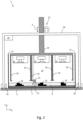
- FIG 2 A second embodiment of a device 1 according to the invention is shown in a schematic side view.
- elements with the same reference numerals correspond to those of the device 1 of the Figure 1 .
- the functionality of these elements is identical to the functionality of the corresponding elements of the device 1 of the Figure 1 .
- Deviating from device 1 of Figure 1 The device 1 of the Figure 2 not only one but several irradiation units 17 arranged next to each other.
- Three irradiation units 17 are provided, although fewer or more irradiation units 17 can also be provided.
- Each of the irradiation units 17 defines an irradiation area on a common carrier 7.
- a workpiece 15 can be produced in each of the irradiation areas.
- the irradiation areas of the irradiation units 17 it is also possible for the irradiation areas of the irradiation units 17 to be directly adjacent to one another or to overlap so that a large workpiece can be produced, with each of the irradiation units 17 being responsible for solidifying a predetermined area of the workpiece.
- the three irradiation areas are located in a common construction chamber 13, which is surrounded by a construction chamber wall 11.
- a gas inlet 23 and a gas outlet 25 are provided for generating a horizontal gas flow over the respective irradiation area.
- a common gas inlet and a common gas outlet 25 can be provided, so that, for example, a gas inlet 23 and a gas outlet 25 are provided only on the outer regions of the irradiation unit carrier 19.
- the device 1 has a common powder application device 21, which can apply powder layers over the entire surface of the carrier 7.
- a separate powder application device can be provided for each of the irradiation regions.
- the device 1 of the Figure 2 has several irradiation units 17, on the one hand larger (common) workpieces can be produced and on the other hand several workpieces 15 can be produced simultaneously, which leads to a reduced process time per workpiece 15.
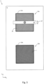
- Figure 3 shows a third embodiment of a device 1 for producing a three-dimensional workpiece, wherein the device 1 of the third embodiment may be, for example, the device 1 of the Figure 1 or the device 1 of the Figure 2
- the device 1 of the Figure 3 comprises a first construction chamber 13a and a second construction chamber 13b. Furthermore, further construction chambers can be provided (not shown).
- the first construction chamber 13a and the second construction chamber 13b are shown in plan view.
- the construction chamber 13a is surrounded by a construction chamber wall 11a and the construction chamber 13b is surrounded by a construction chamber wall 11b.
- the construction chamber 13a or 13b can, for example, be one of the Figure 1 or Figure 2 shown construction chambers 13.
- the construction chambers 13a and 13b are arranged on a common foundation 5.
- the frames 29 are above the first construction chamber 13a, so that a workpiece 15 can be produced within the first construction chamber 13a by a generative layer construction process.
- the elements of the device 1 required for this correspond, for example, to those of the Figure 1 or the Figure 2 .
- the frame 29 moves with the help of the horizontal movement device 35 over the foundation 5 from the first construction chamber 13a to the second construction chamber 13b, as shown by the arrow 37.
- the irradiation unit 17 or the irradiation units 17 are now lowered above the second construction chamber 13b with the help of the vertical movement device 31. above the carrier 7 and a new (second) construction process is started in the second construction chamber 13b.
- the workpiece 15 can cool down in the first construction chamber 13a and can be removed, for example, by lifting the construction chamber wall 11a or through an opening in the construction chamber wall 11a.
- the construction chambers 13, 13a, 13b described here can be large construction chambers with a side length of, for example, more than 50 cm each.
- at least one of the two orthogonal side lengths of the support 7 can be at least 50 cm.
- at least one of the two orthogonal side lengths of the support 7 can be at least 100 cm.
- the supports 7 used here can therefore be supports with a base area of 1 m ⁇ 1 m.
- the device described here has a vertically movable irradiation unit, a relative movement of the irradiation unit takes place relative to the carrier without the carrier having to be moved.
- this has the advantage that no heavy amount of powder and no heavy workpiece have to be moved during the construction process.
- the irradiation unit is moved relative to the construction chamber wall so that the construction chamber wall remains stationary in relation to the raw material powder and no friction occurs at an interface between the construction chamber wall and the raw material powder and thus no disruption of the powder layers occurs. Because the construction chamber wall remains stationary in relation to the raw material powder, it is relatively unproblematic to seal the construction chamber wall to the carrier, ie to ensure that no powder can get through a gap between the construction chamber wall and the carrier. With conventional devices, this sealing is a greater problem, since the carrier must be able to move vertically relative to the construction chamber wall.
Landscapes
- Engineering & Computer Science (AREA)
- Chemical & Material Sciences (AREA)
- Materials Engineering (AREA)
- Manufacturing & Machinery (AREA)
- Physics & Mathematics (AREA)
- Mechanical Engineering (AREA)
- Optics & Photonics (AREA)
- Health & Medical Sciences (AREA)
- Toxicology (AREA)
- Plasma & Fusion (AREA)
- Automation & Control Theory (AREA)
- General Health & Medical Sciences (AREA)
- Ceramic Engineering (AREA)
- Environmental & Geological Engineering (AREA)
- Microelectronics & Electronic Packaging (AREA)
- Powder Metallurgy (AREA)
- Coating Apparatus (AREA)
- Application Of Or Painting With Fluid Materials (AREA)
- Producing Shaped Articles From Materials (AREA)
Applications Claiming Priority (4)
| Application Number | Priority Date | Filing Date | Title |
|---|---|---|---|
| DE102017205027.6A DE102017205027A1 (de) | 2017-03-24 | 2017-03-24 | Vorrichtung und Verfahren zum Herstellen von dreidimensionalen Werkstücken |
| EP22193536.4A EP4116018B1 (fr) | 2017-03-24 | 2018-03-08 | Dispositif et procédé de fabrication de pièces tridimensionnelles |
| EP18709590.6A EP3600726B1 (fr) | 2017-03-24 | 2018-03-08 | Dispositif et procédé de fabrication de pièces tridimensionnelles |
| PCT/EP2018/055770 WO2018172092A1 (fr) | 2017-03-24 | 2018-03-08 | Dispositif et procédé servant à fabriquer des pièces tridimensionnelles |
Related Parent Applications (3)
| Application Number | Title | Priority Date | Filing Date |
|---|---|---|---|
| EP22193536.4A Division EP4116018B1 (fr) | 2017-03-24 | 2018-03-08 | Dispositif et procédé de fabrication de pièces tridimensionnelles |
| EP22193536.4A Division-Into EP4116018B1 (fr) | 2017-03-24 | 2018-03-08 | Dispositif et procédé de fabrication de pièces tridimensionnelles |
| EP18709590.6A Division EP3600726B1 (fr) | 2017-03-24 | 2018-03-08 | Dispositif et procédé de fabrication de pièces tridimensionnelles |
Publications (2)
| Publication Number | Publication Date |
|---|---|
| EP4488065A2 true EP4488065A2 (fr) | 2025-01-08 |
| EP4488065A3 EP4488065A3 (fr) | 2025-03-26 |
Family
ID=61599174
Family Applications (3)
| Application Number | Title | Priority Date | Filing Date |
|---|---|---|---|
| EP22193536.4A Active EP4116018B1 (fr) | 2017-03-24 | 2018-03-08 | Dispositif et procédé de fabrication de pièces tridimensionnelles |
| EP24207753.5A Pending EP4488065A3 (fr) | 2017-03-24 | 2018-03-08 | Dispositif et procédé de fabrication de pièces tridimensionnelles |
| EP18709590.6A Active EP3600726B1 (fr) | 2017-03-24 | 2018-03-08 | Dispositif et procédé de fabrication de pièces tridimensionnelles |
Family Applications Before (1)
| Application Number | Title | Priority Date | Filing Date |
|---|---|---|---|
| EP22193536.4A Active EP4116018B1 (fr) | 2017-03-24 | 2018-03-08 | Dispositif et procédé de fabrication de pièces tridimensionnelles |
Family Applications After (1)
| Application Number | Title | Priority Date | Filing Date |
|---|---|---|---|
| EP18709590.6A Active EP3600726B1 (fr) | 2017-03-24 | 2018-03-08 | Dispositif et procédé de fabrication de pièces tridimensionnelles |
Country Status (6)
| Country | Link |
|---|---|
| US (3) | US11247390B2 (fr) |
| EP (3) | EP4116018B1 (fr) |
| JP (1) | JP6882508B2 (fr) |
| CN (2) | CN114951698B (fr) |
| DE (1) | DE102017205027A1 (fr) |
| WO (1) | WO2018172092A1 (fr) |
Families Citing this family (16)
| Publication number | Priority date | Publication date | Assignee | Title |
|---|---|---|---|---|
| EP3431260B1 (fr) * | 2017-07-21 | 2021-06-02 | CL Schutzrechtsverwaltungs GmbH | Appareil de fabrication additive d'objets tridimensionnels |
| DE102018129027A1 (de) | 2018-11-19 | 2020-05-20 | AMCM GmbH | Verfahren zur additiven Fertigung und System |
| DE102018129024A1 (de) | 2018-11-19 | 2020-05-20 | AMCM GmbH | Verfahren zur additiven Fertigung und System |
| DE102018129028A1 (de) * | 2018-11-19 | 2020-05-20 | AMCM GmbH | Verfahren zur additiven Fertigung und System |
| FR3089447B1 (fr) * | 2018-12-10 | 2022-02-11 | Addup | Machine de fabrication additive avec un actionneur à agencement compact |
| WO2020178220A1 (fr) * | 2019-03-04 | 2020-09-10 | SLM Solutions Group AG | Dispositif et procédé de production d'une pièce tridimensionnelle |
| CN110194669B (zh) * | 2019-05-27 | 2020-11-24 | 华中科技大学 | 一种大型复杂零件的激光选区烧结成形装备、系统及方法 |
| WO2021004926A1 (fr) * | 2019-07-08 | 2021-01-14 | SLM Solutions Group AG | Unité optique et installation destinée à fabriquer une pièce tridimensionnelle |
| EP3851267A1 (fr) | 2020-01-20 | 2021-07-21 | Vito NV | Système et procédé de fabrication de structures tridimensionnelles |
| EP3851266A1 (fr) * | 2020-01-20 | 2021-07-21 | Vito NV | Système et procédé de fabrication de structures tridimensionnelles |
| CN113681885A (zh) * | 2020-05-19 | 2021-11-23 | 广东汉邦激光科技有限公司 | 多工件3d打印装置及多工件3d打印方法 |
| JP7625085B2 (ja) * | 2020-12-08 | 2025-01-31 | ニコン・エスエルエム・ソルーションズ・アクチエンゲゼルシャフト | 資源管理システムおよびこれを有する積層造形施設 |
| CN114535608B (zh) * | 2022-02-25 | 2024-03-19 | 南京晨光集团有限责任公司 | 选区激光熔化条状结构的多件同舱零件排布与扫描策略 |
| DE102022111992A1 (de) | 2022-05-12 | 2023-11-16 | Eos Gmbh Electro Optical Systems | Kalibrierung eines Energiestrahls |
| DE102024105646A1 (de) * | 2024-02-28 | 2025-08-28 | Nikon Slm Solutions Ag | Vorrichtung zum Herstellen eines dreidimensionalen Werkstücks mithilfe eines generativen Schichtbauverfahrens |
| US12528249B2 (en) * | 2024-04-12 | 2026-01-20 | General Electric Company | Powder removal apparatuses for additive manufacturing apparatuses |
Citations (3)
| Publication number | Priority date | Publication date | Assignee | Title |
|---|---|---|---|---|
| EP2878402A1 (fr) | 2013-12-02 | 2015-06-03 | SLM Solutions Group AG | Appareil et procédé de fabrication de pièces tridimensionnelle avec un dispositif de détection de rayonnement |
| EP2961549A1 (fr) | 2013-02-27 | 2016-01-06 | SLM Solutions Group AG | Appareil et méthode de production de pièces de fabrication avec une microstructure sur mesure |
| EP2333848B1 (fr) | 2009-12-10 | 2019-02-13 | LG Innotek Co., Ltd. | Dispositif électroluminescent et boîtier de dispositif électroluminescent |
Family Cites Families (44)
| Publication number | Priority date | Publication date | Assignee | Title |
|---|---|---|---|---|
| DE19649865C1 (de) | 1996-12-02 | 1998-02-12 | Fraunhofer Ges Forschung | Verfahren zur Herstellung eines Formkörpers |
| US7357629B2 (en) * | 2005-03-23 | 2008-04-15 | 3D Systems, Inc. | Apparatus and method for aligning a removable build chamber within a process chamber |
| US7790096B2 (en) * | 2005-03-31 | 2010-09-07 | 3D Systems, Inc. | Thermal management system for a removable build chamber for use with a laser sintering system |
| US7807947B2 (en) * | 2005-05-09 | 2010-10-05 | 3D Systems, Inc. | Laser sintering process chamber gas curtain window cleansing in a laser sintering system |
| US20070126157A1 (en) * | 2005-12-02 | 2007-06-07 | Z Corporation | Apparatus and methods for removing printed articles from a 3-D printer |
| DE102006030350A1 (de) * | 2006-06-30 | 2008-01-03 | Voxeljet Technology Gmbh | Verfahren zum Aufbauen eines Schichtenkörpers |
| GB0813241D0 (en) | 2008-07-18 | 2008-08-27 | Mcp Tooling Technologies Ltd | Manufacturing apparatus and method |
| EP2202016B1 (fr) * | 2008-11-27 | 2012-04-25 | SLM Solutions GmbH | Dispositif d'application de poudre pour une installation de fabrication de pièces usinées en utilisant des couches de poudre à l'aide d'un rayonnement électromagnétique ou un rayonnement de particules |
| US20100155985A1 (en) * | 2008-12-18 | 2010-06-24 | 3D Systems, Incorporated | Apparatus and Method for Cooling Part Cake in Laser Sintering |
| DE102009053190A1 (de) * | 2009-11-08 | 2011-07-28 | FIT Fruth Innovative Technologien GmbH, 92331 | Vorrichtung und Verfahren zur Herstellung eines dreidimensionalen Körpers |
| DE202011003443U1 (de) | 2011-03-02 | 2011-12-23 | Bego Medical Gmbh | Vorrichtung zur generativen Herstellung dreidimensionaler Bauteile |
| DE102011106380B4 (de) * | 2011-06-10 | 2024-10-02 | Concept Laser Gmbh | Vorrichtung zur Herstellung von dreidimensionalen Objekten |
| JP2013049137A (ja) * | 2011-08-30 | 2013-03-14 | Sony Corp | 除粉装置、造形システム及び造形物の製造方法 |
| US9149870B2 (en) * | 2012-09-14 | 2015-10-06 | Aerojet Rocketdyne Of De, Inc. | Additive manufacturing chamber with reduced load |
| JP2014125643A (ja) * | 2012-12-25 | 2014-07-07 | Honda Motor Co Ltd | 三次元造形装置および三次元造形方法 |
| US9669583B2 (en) * | 2013-03-15 | 2017-06-06 | Renishaw Plc | Selective laser solidification apparatus and method |
| EP3782798B1 (fr) * | 2013-04-03 | 2022-03-09 | SLM Solutions Group AG | Procédé et appareil de fabrication de pièces à usiner tridimensionnelles |
| GB201310398D0 (en) | 2013-06-11 | 2013-07-24 | Renishaw Plc | Additive manufacturing apparatus and method |
| US10252333B2 (en) | 2013-06-11 | 2019-04-09 | Renishaw Plc | Additive manufacturing apparatus and method |
| EP2859973B1 (fr) * | 2013-10-10 | 2019-12-04 | SLM Solutions Group AG | Procédé et dispositif de traitement de poudre destiné à être utilisé dans un appareil de fabrication additive de pièces tridimensionnelles |
| EP2862651B1 (fr) * | 2013-10-15 | 2019-07-17 | SLM Solutions Group AG | Procédé et appareil de fabrication additive de pièces tridimensionnelles de grande taille |
| US20150125333A1 (en) * | 2013-11-05 | 2015-05-07 | Gerald J. Bruck | Below surface laser processing of a fluidized bed |
| DE202013009787U1 (de) * | 2013-11-29 | 2013-12-16 | Slm Solutions Gmbh | Anlage mit einer Werkstückerzeugungssektion |
| GB2521191B (en) * | 2013-12-12 | 2016-09-21 | Exmet Ab | Magnetic materials and methods for their manufacture |
| JP2015193187A (ja) * | 2014-03-31 | 2015-11-05 | 日本電子株式会社 | 3次元積層造形装置及び3次元積層造形方法 |
| JP6338422B2 (ja) * | 2014-03-31 | 2018-06-06 | 三菱重工業株式会社 | 三次元積層装置 |
| GB201410484D0 (en) * | 2014-06-12 | 2014-07-30 | Renishaw Plc | Additive manufacturing apparatus and a flow device for use with such apparatus |
| JP5721887B1 (ja) | 2014-06-20 | 2015-05-20 | 株式会社ソディック | 積層造形装置 |
| DE102014218639A1 (de) * | 2014-09-17 | 2016-03-31 | Mtu Aero Engines Gmbh | Vorrichtung und Verfahren zum generativen Aufbauen einer Werkstückanordnung |
| GB201418595D0 (en) * | 2014-10-20 | 2014-12-03 | Renishaw Plc | Additive manufacturing apparatus and methods |
| US20170304894A1 (en) * | 2014-11-10 | 2017-10-26 | Velo3D, Inc. | Printing three-dimensional objects using beam array |
| CN105984147B (zh) * | 2015-02-04 | 2018-11-30 | 三纬国际立体列印科技股份有限公司 | 立体打印装置 |
| EP3067132A1 (fr) * | 2015-03-11 | 2016-09-14 | SLM Solutions Group AG | Procédé et appareil de production d'une pièce de travail tridimensionnelle avec compensation des variations thermiques de la focalisation du laser |
| RU2602329C2 (ru) * | 2015-04-13 | 2016-11-20 | Общество с ограниченной ответственностью Научно-производственный центр "Лазеры и аппаратура ТМ" | Устройство для изготовления объемных изделий |
| US10449606B2 (en) * | 2015-06-19 | 2019-10-22 | General Electric Company | Additive manufacturing apparatus and method for large components |
| WO2017015146A2 (fr) * | 2015-07-17 | 2017-01-26 | Applied Materials, Inc. | Structures de renfort pour fabrication additive |
| EP3120967B1 (fr) * | 2015-07-20 | 2019-06-12 | SLM Solutions Group AG | Procédé et dispositif pour commander un système d'irradiation en fonction d'une géométrie de la pièce à fabriquer |
| KR20180042305A (ko) * | 2015-09-16 | 2018-04-25 | 어플라이드 머티어리얼스, 인코포레이티드 | 적층 제조 시스템을 위한 조절가능한 z축 프린트헤드 모듈 |
| EP3147047B1 (fr) | 2015-09-25 | 2023-08-02 | SLM Solutions Group AG | Appareil de production d'une pièce tridimensionnelle avec un meilleur écoulement de gaz et méthode de production d'une pièce tridimensionnelle |
| US10549346B2 (en) * | 2016-03-30 | 2020-02-04 | Canon Kabushiki Kaisha | Three-dimensional modeling apparatus, three-dimensional model body manufacturing method, and three-dimensional modeling data |
| DE102016114057A1 (de) * | 2016-07-29 | 2018-02-01 | Cl Schutzrechtsverwaltungs Gmbh | Baukammer für eine Vorrichtung zur additiven Herstellung dreidimensionaler Objekte |
| US10661341B2 (en) * | 2016-11-07 | 2020-05-26 | Velo3D, Inc. | Gas flow in three-dimensional printing |
| US10022795B1 (en) | 2017-01-13 | 2018-07-17 | General Electric Company | Large scale additive machine |
| US11123924B2 (en) * | 2017-02-21 | 2021-09-21 | Renishaw Plc | Powder bed fusion apparatus and methods |
-
2017
- 2017-03-24 DE DE102017205027.6A patent/DE102017205027A1/de active Pending
-
2018
- 2018-03-08 CN CN202210598353.0A patent/CN114951698B/zh active Active
- 2018-03-08 EP EP22193536.4A patent/EP4116018B1/fr active Active
- 2018-03-08 EP EP24207753.5A patent/EP4488065A3/fr active Pending
- 2018-03-08 CN CN201880020243.8A patent/CN110461507B/zh active Active
- 2018-03-08 EP EP18709590.6A patent/EP3600726B1/fr active Active
- 2018-03-08 WO PCT/EP2018/055770 patent/WO2018172092A1/fr not_active Ceased
- 2018-03-08 JP JP2019552064A patent/JP6882508B2/ja active Active
- 2018-03-08 US US16/495,958 patent/US11247390B2/en active Active
-
2022
- 2022-01-14 US US17/575,822 patent/US11718027B2/en active Active
-
2023
- 2023-06-22 US US18/212,871 patent/US12030248B2/en active Active
Patent Citations (3)
| Publication number | Priority date | Publication date | Assignee | Title |
|---|---|---|---|---|
| EP2333848B1 (fr) | 2009-12-10 | 2019-02-13 | LG Innotek Co., Ltd. | Dispositif électroluminescent et boîtier de dispositif électroluminescent |
| EP2961549A1 (fr) | 2013-02-27 | 2016-01-06 | SLM Solutions Group AG | Appareil et méthode de production de pièces de fabrication avec une microstructure sur mesure |
| EP2878402A1 (fr) | 2013-12-02 | 2015-06-03 | SLM Solutions Group AG | Appareil et procédé de fabrication de pièces tridimensionnelle avec un dispositif de détection de rayonnement |
Also Published As
| Publication number | Publication date |
|---|---|
| US11247390B2 (en) | 2022-02-15 |
| CN110461507A (zh) | 2019-11-15 |
| DE102017205027A1 (de) | 2018-09-27 |
| CN114951698B (zh) | 2023-10-17 |
| EP4488065A3 (fr) | 2025-03-26 |
| US11718027B2 (en) | 2023-08-08 |
| CN110461507B (zh) | 2022-06-21 |
| US20220134646A1 (en) | 2022-05-05 |
| EP3600726B1 (fr) | 2022-10-19 |
| WO2018172092A1 (fr) | 2018-09-27 |
| EP4116018A1 (fr) | 2023-01-11 |
| EP4116018B1 (fr) | 2025-01-29 |
| US20200031043A1 (en) | 2020-01-30 |
| US12030248B2 (en) | 2024-07-09 |
| JP6882508B2 (ja) | 2021-06-02 |
| CN114951698A (zh) | 2022-08-30 |
| EP3600726A1 (fr) | 2020-02-05 |
| JP2020514136A (ja) | 2020-05-21 |
| US20230330931A1 (en) | 2023-10-19 |
Similar Documents
| Publication | Publication Date | Title |
|---|---|---|
| EP4116018B1 (fr) | Dispositif et procédé de fabrication de pièces tridimensionnelles | |
| EP3624966B1 (fr) | Dispositif et procédé pour la fabrication des pièces tridimensionnelles | |
| DE10053742C2 (de) | Vorrichtung zum Sintern, Abtragen und/oder Beschriften mittels elektromagnetischer gebündelter Strahlung sowie Verfahren zum Betrieb der Vorrichtung | |
| EP3866999B1 (fr) | Procédé et dispositif de fabrication d'une pièce tridimensionnelle | |
| DE102014209161A1 (de) | Steuereinheit, Vorrichtung und Verfahren zum Herstellen eines dreidimensionalen Objekts | |
| EP3242762A1 (fr) | Dispositif et procédé génératif de construction par couches permettant de produire un objet tridimensionnel au moyen d'une pluralité de rayons | |
| WO2001007239A1 (fr) | Procede et dispositif pour produire des elements a partir d'une combinaison de materiaux | |
| WO2011066989A1 (fr) | Unité de rayonnement optique pour une installation de fabrication de pièces par l'application d'un rayonnement laser sur des couches de poudre | |
| DE102015116886A1 (de) | Dreidimensionaler Drucker | |
| DE102007014968A1 (de) | Vorrichtung zur Herstellung von Gegenständen | |
| DE102018202506A1 (de) | Additives Herstellverfahren mit kontrollierter Verfestigung und zugehörige Vorrichtung | |
| EP3642038B1 (fr) | Dispositif et procédé de fabrication générative d'un objet tridimensionnel avec systeme de levage | |
| DE102010046467A1 (de) | Vorrichtung zum Herstellen, Reparieren und/oder Austauschen eines Bauteils mittels eines durch Energiestrahlung verfestigbaren Pulvers, sowie ein Verfahren und ein gemäß dem Verfahren hergestellten Bauteils | |
| DE102017223643B4 (de) | Verfahren und Vorrichtung zum generativen Herstellen eines Bauteils | |
| WO1996014203A1 (fr) | Procede et dispositif pour la production d'un objet a trois dimensions | |
| EP3482854B1 (fr) | Procédé de fabrication d'un demi-produit et d'une pièce à usiner | |
| DE202004021862U1 (de) | Vorrichtung zum Herstellen von dreidimensionalen Objekten | |
| EP4540008A1 (fr) | Appareil de levage pour un dispositif de support d`une installation de fabrication additive d`une pièce tridimensionnelle | |
| EP3986645B1 (fr) | Procédé et dispositif de fabrication d'une pièce multi-matériaux | |
| DE102019215388A1 (de) | Vorrichtung mit variablem Fokus zur Herstellung von Gegenständen durch schichtweises Aufbauen aus pulverförmigem Werkstoff | |
| DE102024207373A1 (de) | Hatch-Strategie beim Verfestigen des Aufbaumaterials in einem additiven Herstellverfahren | |
| DE102024207374A1 (de) | Hatch-Strategie beim Verfestigen des Aufbaumaterials in einem additiven Herstellverfahren | |
| WO2025180890A1 (fr) | Dispositif de fabrication d'une pièce à usiner en trois dimensions au moyen d'un procédé de stratification générative | |
| EP3996858A1 (fr) | Unité optique et installation destinée à fabriquer une pièce tridimensionnelle | |
| WO2025209822A1 (fr) | Procédé de fabrication de composants couche par couche, appareil de fabrication et produit programme d'ordinateur |
Legal Events
| Date | Code | Title | Description |
|---|---|---|---|
| PUAI | Public reference made under article 153(3) epc to a published international application that has entered the european phase |
Free format text: ORIGINAL CODE: 0009012 |
|
| STAA | Information on the status of an ep patent application or granted ep patent |
Free format text: STATUS: REQUEST FOR EXAMINATION WAS MADE |
|
| 17P | Request for examination filed |
Effective date: 20241021 |
|
| AC | Divisional application: reference to earlier application |
Ref document number: 3600726 Country of ref document: EP Kind code of ref document: P Ref document number: 4116018 Country of ref document: EP Kind code of ref document: P |
|
| AK | Designated contracting states |
Kind code of ref document: A2 Designated state(s): AL AT BE BG CH CY CZ DE DK EE ES FI FR GB GR HR HU IE IS IT LI LT LU LV MC MK MT NL NO PL PT RO RS SE SI SK SM TR |
|
| REG | Reference to a national code |
Ref country code: DE Ref legal event code: R079 Free format text: PREVIOUS MAIN CLASS: B33Y0030000000 Ipc: B22F0010280000 |
|
| PUAL | Search report despatched |
Free format text: ORIGINAL CODE: 0009013 |
|
| AK | Designated contracting states |
Kind code of ref document: A3 Designated state(s): AL AT BE BG CH CY CZ DE DK EE ES FI FR GB GR HR HU IE IS IT LI LT LU LV MC MK MT NL NO PL PT RO RS SE SI SK SM TR |
|
| RIC1 | Information provided on ipc code assigned before grant |
Ipc: B22F 12/49 20210101ALN20250219BHEP Ipc: B22F 12/44 20210101ALN20250219BHEP Ipc: B22F 12/41 20210101ALN20250219BHEP Ipc: B22F 10/32 20210101ALN20250219BHEP Ipc: B33Y 30/00 20150101ALI20250219BHEP Ipc: B33Y 10/00 20150101ALI20250219BHEP Ipc: B29C 64/259 20170101ALI20250219BHEP Ipc: B29C 64/153 20170101ALI20250219BHEP Ipc: B22F 12/86 20210101ALI20250219BHEP Ipc: B22F 12/70 20210101ALI20250219BHEP Ipc: B22F 12/48 20210101ALI20250219BHEP Ipc: B22F 12/47 20210101ALI20250219BHEP Ipc: B22F 12/00 20210101ALI20250219BHEP Ipc: B22F 10/322 20210101ALI20250219BHEP Ipc: B22F 10/28 20210101AFI20250219BHEP |