EP4488075A1 - Bande de roulement pour un pneu de véhicule - Google Patents
Bande de roulement pour un pneu de véhicule Download PDFInfo
- Publication number
- EP4488075A1 EP4488075A1 EP24183957.0A EP24183957A EP4488075A1 EP 4488075 A1 EP4488075 A1 EP 4488075A1 EP 24183957 A EP24183957 A EP 24183957A EP 4488075 A1 EP4488075 A1 EP 4488075A1
- Authority
- EP
- European Patent Office
- Prior art keywords
- groove
- radially
- region
- tread
- profile
- Prior art date
- Legal status (The legal status is an assumption and is not a legal conclusion. Google has not performed a legal analysis and makes no representation as to the accuracy of the status listed.)
- Granted
Links
Images


Classifications
-
- B—PERFORMING OPERATIONS; TRANSPORTING
- B60—VEHICLES IN GENERAL
- B60C—VEHICLE TYRES; TYRE INFLATION; TYRE CHANGING; CONNECTING VALVES TO INFLATABLE ELASTIC BODIES IN GENERAL; DEVICES OR ARRANGEMENTS RELATED TO TYRES
- B60C11/00—Tyre tread bands; Tread patterns; Anti-skid inserts
- B60C11/03—Tread patterns
- B60C11/12—Tread patterns characterised by the use of narrow slits or incisions, e.g. sipes
- B60C11/1272—Width of the sipe
- B60C11/1281—Width of the sipe different within the same sipe, i.e. enlarged width portion at sipe bottom or along its length
-
- B—PERFORMING OPERATIONS; TRANSPORTING
- B60—VEHICLES IN GENERAL
- B60C—VEHICLE TYRES; TYRE INFLATION; TYRE CHANGING; CONNECTING VALVES TO INFLATABLE ELASTIC BODIES IN GENERAL; DEVICES OR ARRANGEMENTS RELATED TO TYRES
- B60C11/00—Tyre tread bands; Tread patterns; Anti-skid inserts
- B60C11/03—Tread patterns
- B60C11/032—Patterns comprising isolated recesses
- B60C11/0323—Patterns comprising isolated recesses tread comprising channels under the tread surface, e.g. for draining water
-
- B—PERFORMING OPERATIONS; TRANSPORTING
- B60—VEHICLES IN GENERAL
- B60C—VEHICLE TYRES; TYRE INFLATION; TYRE CHANGING; CONNECTING VALVES TO INFLATABLE ELASTIC BODIES IN GENERAL; DEVICES OR ARRANGEMENTS RELATED TO TYRES
- B60C11/00—Tyre tread bands; Tread patterns; Anti-skid inserts
- B60C11/03—Tread patterns
- B60C11/04—Tread patterns in which the raised area of the pattern consists only of continuous circumferential ribs, e.g. zig-zag
- B60C11/042—Tread patterns in which the raised area of the pattern consists only of continuous circumferential ribs, e.g. zig-zag further characterised by the groove cross-section
-
- B—PERFORMING OPERATIONS; TRANSPORTING
- B60—VEHICLES IN GENERAL
- B60C—VEHICLE TYRES; TYRE INFLATION; TYRE CHANGING; CONNECTING VALVES TO INFLATABLE ELASTIC BODIES IN GENERAL; DEVICES OR ARRANGEMENTS RELATED TO TYRES
- B60C11/00—Tyre tread bands; Tread patterns; Anti-skid inserts
- B60C11/03—Tread patterns
- B60C11/04—Tread patterns in which the raised area of the pattern consists only of continuous circumferential ribs, e.g. zig-zag
- B60C11/042—Tread patterns in which the raised area of the pattern consists only of continuous circumferential ribs, e.g. zig-zag further characterised by the groove cross-section
- B60C11/045—Tread patterns in which the raised area of the pattern consists only of continuous circumferential ribs, e.g. zig-zag further characterised by the groove cross-section the groove walls having a three-dimensional shape
-
- B—PERFORMING OPERATIONS; TRANSPORTING
- B60—VEHICLES IN GENERAL
- B60C—VEHICLE TYRES; TYRE INFLATION; TYRE CHANGING; CONNECTING VALVES TO INFLATABLE ELASTIC BODIES IN GENERAL; DEVICES OR ARRANGEMENTS RELATED TO TYRES
- B60C11/00—Tyre tread bands; Tread patterns; Anti-skid inserts
- B60C11/03—Tread patterns
- B60C11/13—Tread patterns characterised by the groove cross-section, e.g. for buttressing or preventing stone-trapping
- B60C11/1307—Tread patterns characterised by the groove cross-section, e.g. for buttressing or preventing stone-trapping with special features of the groove walls
- B60C11/1323—Tread patterns characterised by the groove cross-section, e.g. for buttressing or preventing stone-trapping with special features of the groove walls asymmetric
Definitions
- the invention relates to a tread for a vehicle tire, wherein a profile groove with a radially upper region and a radially lower region and with two groove flanks is formed in the tread, wherein in the radially upper region of the profile groove lateral overhangs are formed on the groove flanks such that a groove width in the radially upper region is smaller than in the radially lower region, wherein the profile groove assumes a zigzag-shaped and/or curved course in the radially upper region and assumes a straight course in the radially lower region.
- Lateral overhangs in the radially upper areas of profile grooves have the advantage that, when a tread equipped in this way is new, there is more material on the tread than without the overhangs, which can lead to better dry grip and slower wear in the radial direction.
- Another advantage of a smaller groove width in the radially upper area can be that the groove flanks on the lateral overhangs can support each other when the tread is loaded, which can lead to improved rigidity. Because the profile groove has a greater groove width in the radially lower area than in the radially upper area with the lateral overhangs, a good drainage function can be ensured at the same time.
- a wave-shaped profile groove in a radially upper area, especially on a tread, can create additional edge length, which can have a positive effect on the traction properties, in particular on the wet grip of a vehicle tire equipped with a correspondingly designed profile groove.
- DE 10 2020 204 226 A1 describes a circumferential groove which, in the radial direction and starting at the tread periphery, is composed of an outer groove and an inner groove which, at its widest point, has a width which is at least 1 mm greater than the width of the outer groove, whereby the outer groove runs in a wave shape.
- a vehicle tire in particular a vehicle tire used on a steering axle, can be subjected to greater stress from the direction of an axial outer side than from the direction of an axial center.
- an asymmetrical design of a groove cross-section can offer the advantage that the transverse stiffness can be set differently on both sides of the profile groove.
- an increased susceptibility to cracking on an axially outward-facing side of the profile groove can be specifically counteracted by a suitable asymmetrical design, in particular of the groove base.
- the invention is based on the object of creating a tread for a vehicle tire which has both good wet properties and optimized stiffness and resilience.
- the stated object is achieved according to the invention in that, viewed in a sectional surface perpendicular to the longitudinal extension of the profile groove, the radially lower region is formed asymmetrically to a radial direction.
- the invention recognizes that a profile groove that is already complexly designed in a radially upper region along a longitudinal extension can be further optimized in a radially lower region in the depth and width direction.
- both a cross section perpendicular to the radial direction in the radially upper region is qualitatively different from such a cross section in the radially lower region and a cross section perpendicular to the longitudinal extension of the profile groove can be changed along this longitudinal extension.
- the direction designations axial, in axial direction, radial, in radial direction and in circumferential direction refer to the tread arranged as intended on a vehicle tire with, in turn, vehicle tire that is properly fitted to a vehicle.
- the radial direction refers to a direction that is perpendicular to the axis of rotation of the vehicle tire and intersects the axis of rotation.
- inwards refers to the orientation that faces the axis of rotation in the radial direction.
- outwards refers to the orientation that faces away from the axis of rotation in the radial direction.
- the circumferential direction describes the direction of a rolling movement about the axis of rotation.
- the axial direction refers to a direction parallel to the axis of rotation. Pointing axially inwards refers to an orientation that is axially facing a tire equator plane or a tire equator line.
- the tire equatorial plane is a plane perpendicular to the rotational axis of the vehicle tire, passing through the center of the axial width of the vehicle tire, with the tire equatorial line running in the tire equatorial plane and on the surface of the vehicle tire.
- the transverse direction is a direction consisting of components of the radial direction and/or the axial direction.
- the circumferential direction and the transverse direction can run on a base surface of the vehicle tire.
- the base surface coincides with the smooth surface that the vehicle tire would have if no small-scale profile elements, such as grooves or radially protruding ribs, were provided.
- Small-scale profile elements are characterized in at least one of the three dimensions radial direction, axial direction and circumferential direction by a dimension and/or by a radius of curvature that is less than or equal to a maximum profile depth in the vehicle tire.
- the base surface is physically retained wherever no such profile elements are provided. The retained sections of the base surface can be at least partially intended for contact with a road surface.
- the base surface continues as an imaginary surface above the groove; where, for example, a radially protruding rib is arranged on the tread, the base surface continues as an imaginary surface below the radially protruding rib.
- the tread groove is preferably a circumferential groove, i.e. a groove that extends over the entire circumference of a vehicle tire equipped with the tread and opens into itself.
- the cross-section perpendicular to the longitudinal extension of the profile groove in the radially lower region has no kinks, but can be described throughout by well-defined tangents.
- all curves in the cross-section can preferably be described with radii of curvature of more than 3 mm.
- a transition to the radially upper region does not have to be affected by this, but can have folds and/or curves that can be described by a radius of curvature of less than 3 mm.
- the radially lower region of the profile groove can be designed asymmetrically to the radial direction in different ways.
- the profile groove can comprise a groove base, wherein the groove base in the radially lower region of the profile groove can merge into the first groove flank in a first curved partial region and/or can merge into the second groove flank in a second curved partial region.
- a minimum radius of curvature characterizing the first curved partial region is preferably smaller than a minimum radius of curvature characterizing the second curved partial region. If the curved partial regions are circular arcs, each curved partial region is characterized by only one radius of curvature, which then counts as the minimum radius of curvature.
- the second groove flank points axially outwards and the first groove flank points in the direction of the tire equator.
- a smaller curvature on the axial outside and the associated lower susceptibility to cracking allow for greater stress on this side of the tread.
- a ratio between the minimum radius of curvature characterizing the first curved portion and the minimum radius of curvature characterizing the second curved portion is between 0.3 and 0.7 and preferably between 0.45 and 0.55.
- the groove base can run in a straight line between the curved sections. In a preferred embodiment, however, the groove base between the two curved sections is also curved.
- a minimum radius of curvature characterizing the groove base can be in a ratio of 2 to 3, preferably 2.4 to 2.6, to the radius of curvature characterizing the second curved section.
- the first curved section, the second curved section and the groove base can each be described by a circular arc, with the circular arcs merging tangentially into one another and the radially deepest point of the profile groove being located at the point of contact between the first curved section and the groove base.
- the entire radially lower region of the profile groove can be continuously curved in the cross-section perpendicular to the longitudinal extent.
- a straight partial region of a respective groove flank can adjoin radially above the first curved partial region and/or radially above the second curved partial region within the radially lower region.
- the transition between the first curved partial region and a straight partial region of the first groove flank can take place radially further down than the transition between the second curved partial region and a straight partial region of the second groove flank.
- a transition takes place from the first curved partial region to the straight partial region of the first groove flank, but not from the second curved partial region to a straight partial region of the second groove flank; in other words, the second curved section in the cross-section of the radially lower region of the profile groove that is perpendicular to the longitudinal direction can extend to the transition into the radially upper region without a straight partial region of the second groove flank being arranged in the radially lower region.
- the groove flanks preferably have angles of inclination relative to the radial direction.
- An angle of inclination of a groove flank can also be defined locally as an angle of inclination of a Tangent can be determined on a curved partial area.
- Angles of inclination of the groove flanks are positive if they open radially upwards and away from the respective opposite groove flank, so that a V-shaped groove would, for example, have two groove flanks inclined at positive angles.
- the angles of inclination of the groove flanks in the radially lower area are preferably consistently positive.
- a transverse stiffness in the axially outer direction can be increased compared to the axially inner direction by selecting a minimum angle of inclination of the second groove flank in the radially lower area that is greater than a minimum angle of inclination of the first groove flank in the radially lower area. In this way, a greater load on the tread from the axially outside can be specifically counteracted.
- a minimum angle of inclination of a groove flank in the radially lower region is preferably present in the region of a straight partial region of the groove flank and/or can be present at a radially upper end of the radially lower region.
- a minimum angle of inclination of the first groove flank in the radially lower region and a minimum angle of inclination of the second groove flank in the radially lower region can be in a ratio of between 1:3 and 1:2.
- the minimum angle of inclination of the first groove flank in the radially lower region can be between 4° and 8°.
- the boundary between the radially upper region and the radially lower region may be defined at the radial level of a radially lower end of the lateral overhangs and/or where the groove width begins to decrease from maximum tread depth and looking towards the base surface.
- bevelled transitions can be formed on the groove flanks. If the groove width in the area of the radial extension of the bevelled transitions is smaller than in positions further down in the radially lower area, the bevelled transitions can be assigned to the radially upper area.
- the bevelled transitions can have angles of inclination relative to the radial direction in a cross-section perpendicular to the longitudinal extension of the profile groove, with the angles of inclination being open radially upwards and towards the respective opposite groove flank, so that the bevelled transitions cover the radially lower Cover the area.
- An angle of inclination can be between 50° and 70°, measured in the middle of a radial extension or a width extension of a bevelled transition.
- the lateral overhangs can be designed in such a way that a radial region of constant groove width is produced.
- the groove flanks on the lateral overhangs in the radial region of constant groove width can run parallel to the radial direction.
- a radial extension proportion of the radial region of constant groove width in the radially upper region can be between 0.1 and 0.5.
- Chamfers can be formed on the lateral overhangs on the groove flanks in the radially upper area as transitions to the base surface of the tread.
- the chamfers can enclose angles of inclination with the radial direction, with the angles of inclination being open radially outwards and away from the respective opposite groove flank, so that the groove width increases radially outwards in the radial extension area of the chamfers.
- An angle of inclination can be between 20° and 40°, measured in the middle of a radial extension or a width extension of a chamfer.
- Transitions between the radially lower region of the profile groove, the bevelled transitions, the radial region of constant groove width and/or the chamfers in the radially upper region of the profile groove are preferably rounded so that the entire cross-section of the profile groove in a cutting surface perpendicular to the longitudinal extension can preferably be described by well-defined tangents.
- the groove width preferably assumes a minimum value in the radially upper region; in other words, the smallest groove width, considered over the entire radial depth of the profile groove, is preferably in the radially upper region.
- the minimum value is preferably between 0.5 mm and 5 mm, more preferably between 1 mm and 1.2 mm.
- the minimum value is preferably reached in the radial region of constant groove width, radially above the beveled transitions and/or radially below the chamfers.
- the groove width can assume the minimum value at a radial depth between 25% and 45%, preferably at 30% of the radial depth of the profile groove.
- the groove width preferably assumes a maximum value in the radially lower region, so that in other words the largest groove width, considered over the entire depth of the profile groove, is present in the radially lower region.
- the maximum value is preferably between 5 mm and 15 mm.
- the maximum value can be reached at the radially outer end of the radially lower region.
- the groove width can assume the maximum value at a radial depth between 50% and 85% of the radial depth of the profile groove.
- a zigzag and/or curved profile of the profile groove in the radially upper region is given, for example, when a line running in the middle of the groove width on the base surface takes on the shape of a sine curve. If the groove width is constant along the longitudinal extent of the profile groove, the flanks of the profile groove in the radially upper region follow the line in the middle of the groove width.
- a zigzag profile has corners that can be rounded with a small radius of less than 3 mm; a curved profile is characterized by curvatures with radii of more than 3 mm.
- the profile is preferably either zigzag or curved within a profile groove; however, embodiments are also conceivable in which zigzag and curved profiles are arranged one after the other.
- zigzag and/or curved profile does not have to be symmetrical.
- a zigzag pattern may consist of alternating long and short sections, with long sections being longer than short sections and a pair of long and short sections each enclosing an angle of 90°.
- a periodicity of the zigzag and/or curved course in the radially upper area can be in a ratio of 1:3 to 1:1 to a pitch length of a profile formed in the tread.
- An example of a periodicity would be the wavelength of the sine curve in the case of a sinusoidal course and a pair of one long and one short section in the case of the zigzag course consisting of long and short sections.
- the periodicity can be exact, with similar sections being arranged one behind the other along the longitudinal extension of the profile groove in identical lengths; alternatively, the periodicity can be modulated within the framework of a known pitch length variation, with similar sections scaled proportionally to a respective pitch length.
- the zigzag and/or curved course in the radially upper area can cover a range of between 2 mm and 8 mm perpendicular to the longitudinal extension of the profile groove along this longitudinal extension.
- An example of such a range would be, in the case of a sinusoidal course, twice the amplitude of the sine curve, i.e. the range between wave troughs and wave crests measured perpendicular to the x-axis.
- Vehicle tires designed according to the invention are tires of any design, in particular radial tires, and tires of any type, in particular pneumatic vehicle tires for motor vehicles, such as passenger cars, light trucks or commercial vehicles.
- the invention is particularly advantageous for use on vehicle tires for trucks in long-distance transport.
- Figure 1 shows a profile groove 1, which extends as a circumferential groove around a circumferential direction running from top to bottom in the drawing plane.
- the axial direction runs from left to right in the drawing plane, with an axial outer side located on the right.
- a groove bottom 18 in the embodiment shown runs straight along the circumferential direction.
- lateral overhangs 6 are designed in such a way that a zigzag shape is produced. The lateral overhangs 6 merge with bevels 8 into the base surface 10 of the tread.
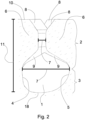
- Figure 2 shows a sectional view of the profile groove 1 in a cutting plane perpendicular to the circumferential direction according to the Fig. 1 marked position II-II.
- the radially lower region 3 extends between a groove bottom 18 and the radial start of the lateral overhangs 6 on the groove flanks 4, 5, where a groove width begins to decrease radially outwards.
- the radially upper region 2 extends between the radially outer end of the radially inner region 3 and the base surface 10 on the running surface of the tread.
- the lateral overhangs 6 on the groove flanks 4, 5 merge with chamfers 8 into the base surface 10 and with bevelled transitions 9 into the radially lower region 3.
- a minimum value of the groove width 7 is reached in the radially upper region 2 and there in a radial region of constant groove width between the chamfers 8 and the bevelled transitions 9 (cf. the horizontal scale bar in the drawing plane in the radially upper region 2).
- a maximum value of the groove width 7 is present at the boundary between the radially lower region 3 and the radially upper region 2 (cf. the horizontal scale bar in the drawing plane in the radially lower region 3).
- the maximum value is reached at approximately 70% of the radial depth 11 of the profile groove 1 measured between the base surface 10 and the groove bottom 18 (cf. the scale bar running from top to bottom in the drawing plane).
- Figure 3 shows, based on a further embodiment, an asymmetrical design of the radially lower region 3 of a profile groove 1 in a sectional view, wherein the sectional plane is perpendicular to the circumferential direction.
- the illustration is only schematically shown, in particular with regard to the transition to the radially upper region 2, and does not take into account, for example, any possibly advantageous and/or technically necessary roundings at the transitions to the lateral overhangs 6.
- the groove base 18 merges in a first curved partial region 12 into a straight partial region of the first groove flank 4 and in a second curved partial region 13 into a straight partial region of the second groove flank 5.
- a radius of curvature 14 characterizing the first curved partial area 12 is smaller than a radius of curvature 15 characterizing the second curved partial area 13.
- the radii 14, 15 are in a ratio of 1:2.
- the groove flanks 4, 5 have angles of inclination 16, 17 with respect to the radial direction.
- a minimum angle of inclination 16 of the first groove flank 4 in the radially lower area 3 is in the straight partial area of the first groove flank 4 and a minimum angle of inclination 17 of the second groove flank 5 in the radially lower area 3 is in the straight partial area of the second groove flank 5.
- the two minimum angles of inclination 16, 17 are in a ratio of approximately 2:5 in the example shown.
- the groove bottom 18 between the two curved sections 12, 13 is curved in the example shown.
- a radius of curvature 19 characterizing the groove bottom 18 is in Fig. 3 not shown in full length.
- the radius 19 has a ratio of 2.5 to the radius of curvature 15 characterizing the second curved partial area 13.
Landscapes
- Engineering & Computer Science (AREA)
- Mechanical Engineering (AREA)
- Tires In General (AREA)
Applications Claiming Priority (1)
| Application Number | Priority Date | Filing Date | Title |
|---|---|---|---|
| DE102023206286.0A DE102023206286A1 (de) | 2023-07-03 | 2023-07-03 | Laufstreifen für einen Fahrzeugreifen |
Publications (2)
| Publication Number | Publication Date |
|---|---|
| EP4488075A1 true EP4488075A1 (fr) | 2025-01-08 |
| EP4488075B1 EP4488075B1 (fr) | 2026-03-18 |
Family
ID=91664816
Family Applications (1)
| Application Number | Title | Priority Date | Filing Date |
|---|---|---|---|
| EP24183957.0A Active EP4488075B1 (fr) | 2023-07-03 | 2024-06-24 | Bande de roulement pour un pneu de véhicule |
Country Status (2)
| Country | Link |
|---|---|
| EP (1) | EP4488075B1 (fr) |
| DE (1) | DE102023206286A1 (fr) |
Citations (5)
| Publication number | Priority date | Publication date | Assignee | Title |
|---|---|---|---|---|
| US2637362A (en) * | 1950-07-14 | 1953-05-05 | Us Rubber Co | Stone-ejecting tire tread |
| US2843172A (en) * | 1955-08-15 | 1958-07-15 | Us Rubber Co | Stone rejecting tire tread |
| EP3888948A1 (fr) * | 2020-04-01 | 2021-10-06 | Continental Reifen Deutschland GmbH | Pneumatiques de vehicule, en particulier pour un vehicule utilitaire |
| EP3974208A1 (fr) * | 2020-09-24 | 2022-03-30 | Continental Reifen Deutschland GmbH | Pneus de véhicule |
| DE102020212560A1 (de) | 2020-10-05 | 2022-04-07 | Continental Reifen Deutschland Gmbh | Fahrzeugluftreifen mit Umfangsrille |
-
2023
- 2023-07-03 DE DE102023206286.0A patent/DE102023206286A1/de active Pending
-
2024
- 2024-06-24 EP EP24183957.0A patent/EP4488075B1/fr active Active
Patent Citations (6)
| Publication number | Priority date | Publication date | Assignee | Title |
|---|---|---|---|---|
| US2637362A (en) * | 1950-07-14 | 1953-05-05 | Us Rubber Co | Stone-ejecting tire tread |
| US2843172A (en) * | 1955-08-15 | 1958-07-15 | Us Rubber Co | Stone rejecting tire tread |
| EP3888948A1 (fr) * | 2020-04-01 | 2021-10-06 | Continental Reifen Deutschland GmbH | Pneumatiques de vehicule, en particulier pour un vehicule utilitaire |
| DE102020204226A1 (de) | 2020-04-01 | 2021-10-07 | Continental Reifen Deutschland Gmbh | Fahrzeugluftreifen, insbesondere Nutzfahrzeugreifen |
| EP3974208A1 (fr) * | 2020-09-24 | 2022-03-30 | Continental Reifen Deutschland GmbH | Pneus de véhicule |
| DE102020212560A1 (de) | 2020-10-05 | 2022-04-07 | Continental Reifen Deutschland Gmbh | Fahrzeugluftreifen mit Umfangsrille |
Also Published As
| Publication number | Publication date |
|---|---|
| DE102023206286A1 (de) | 2025-01-09 |
| EP4488075B1 (fr) | 2026-03-18 |
Similar Documents
| Publication | Publication Date | Title |
|---|---|---|
| DE2951744C2 (de) | Luftreifen für Motorräder | |
| EP4225594B1 (fr) | Pneu de véhicule à canal circonférentiel | |
| EP3256333B1 (fr) | Pneumatique de véhicule | |
| DE69905923T2 (de) | Luftreifen für motorfahrzeug, insbesondere für lkw und dergleichen | |
| EP4351886B1 (fr) | Pneumatique pour un véhicule | |
| DE4108745A1 (de) | Luftreifen | |
| DE102004024162A1 (de) | Luftreifen | |
| EP4488075B1 (fr) | Bande de roulement pour un pneu de véhicule | |
| DE69933101T2 (de) | Fahrzeugreifen | |
| WO2024051901A1 (fr) | Pneu de véhicule | |
| EP4368416B1 (fr) | Bandage pneumatique pour véhicules | |
| WO2025008030A1 (fr) | Bande de roulement pour pneumatique de véhicule | |
| DE102019214093A1 (de) | Fahrzeugluftreifen | |
| DE102019207297A1 (de) | Fahrzeugluftreifen | |
| EP4512638B1 (fr) | Bande de roulement pour un pneu de véhicule et pneu de véhicule | |
| EP4520551B1 (fr) | Bande de roulement pour pneu de véhicule et pneu de véhicule adapté à l'hiver | |
| EP4342687B1 (fr) | Pneumatique pour véhicules | |
| EP4382317B1 (fr) | Bande de roulement pour un pneu de véhicule | |
| WO2026061675A1 (fr) | Bande de roulement et pneu de véhicule présentant de bonnes propriétés sur la neige et anti-bruit | |
| EP4363243B1 (fr) | Pneumatique de véhicule | |
| DE102024205176A1 (de) | Laufstreifen und Fahrzeugreifen mit Selbstreinigungsstruktur | |
| EP4368415A1 (fr) | Bandage pneumatique pour véhicules | |
| EP4722003A1 (fr) | Bandage pneumatique et bande de roulement avec des bords de neige combinés localement à des chanfreins | |
| EP4733086A1 (fr) | Bandage pneumatique pour véhicule | |
| DE102023200943A1 (de) | Laufstreifen für einen Fahrzeugreifen |
Legal Events
| Date | Code | Title | Description |
|---|---|---|---|
| PUAI | Public reference made under article 153(3) epc to a published international application that has entered the european phase |
Free format text: ORIGINAL CODE: 0009012 |
|
| STAA | Information on the status of an ep patent application or granted ep patent |
Free format text: STATUS: THE APPLICATION HAS BEEN PUBLISHED |
|
| AK | Designated contracting states |
Kind code of ref document: A1 Designated state(s): AL AT BE BG CH CY CZ DE DK EE ES FI FR GB GR HR HU IE IS IT LI LT LU LV MC ME MK MT NL NO PL PT RO RS SE SI SK SM TR |
|
| STAA | Information on the status of an ep patent application or granted ep patent |
Free format text: STATUS: REQUEST FOR EXAMINATION WAS MADE |
|
| 17P | Request for examination filed |
Effective date: 20250708 |
|
| GRAP | Despatch of communication of intention to grant a patent |
Free format text: ORIGINAL CODE: EPIDOSNIGR1 |
|
| STAA | Information on the status of an ep patent application or granted ep patent |
Free format text: STATUS: GRANT OF PATENT IS INTENDED |
|
| INTG | Intention to grant announced |
Effective date: 20251124 |
|
| GRAS | Grant fee paid |
Free format text: ORIGINAL CODE: EPIDOSNIGR3 |
|
| GRAA | (expected) grant |
Free format text: ORIGINAL CODE: 0009210 |
|
| STAA | Information on the status of an ep patent application or granted ep patent |
Free format text: STATUS: THE PATENT HAS BEEN GRANTED |
|
| AK | Designated contracting states |
Kind code of ref document: B1 Designated state(s): AL AT BE BG CH CY CZ DE DK EE ES FI FR GB GR HR HU IE IS IT LI LT LU LV MC ME MK MT NL NO PL PT RO RS SE SI SK SM TR |
|
| REG | Reference to a national code |
Ref country code: CH Ref legal event code: F10 Free format text: ST27 STATUS EVENT CODE: U-0-0-F10-F00 (AS PROVIDED BY THE NATIONAL OFFICE) Effective date: 20260318 Ref country code: GB Ref legal event code: FG4D Free format text: NOT ENGLISH |
|
| REG | Reference to a national code |
Ref country code: IE Ref legal event code: FG4D Free format text: LANGUAGE OF EP DOCUMENT: GERMAN |
|
| REG | Reference to a national code |
Ref country code: DE Ref legal event code: R096 Ref document number: 502024000887 Country of ref document: DE |