EP4488099A1 - Système de commande électrique et chargeur de véhicule électrique - Google Patents
Système de commande électrique et chargeur de véhicule électrique Download PDFInfo
- Publication number
- EP4488099A1 EP4488099A1 EP23386054.3A EP23386054A EP4488099A1 EP 4488099 A1 EP4488099 A1 EP 4488099A1 EP 23386054 A EP23386054 A EP 23386054A EP 4488099 A1 EP4488099 A1 EP 4488099A1
- Authority
- EP
- European Patent Office
- Prior art keywords
- contactor
- pyro
- switch
- control system
- fuse
- Prior art date
- Legal status (The legal status is an assumption and is not a legal conclusion. Google has not performed a legal analysis and makes no representation as to the accuracy of the status listed.)
- Pending
Links
Images

Classifications
-
- B—PERFORMING OPERATIONS; TRANSPORTING
- B60—VEHICLES IN GENERAL
- B60L—PROPULSION OF ELECTRICALLY-PROPELLED VEHICLES; SUPPLYING ELECTRIC POWER FOR AUXILIARY EQUIPMENT OF ELECTRICALLY-PROPELLED VEHICLES; ELECTRODYNAMIC BRAKE SYSTEMS FOR VEHICLES IN GENERAL; MAGNETIC SUSPENSION OR LEVITATION FOR VEHICLES; MONITORING OPERATING VARIABLES OF ELECTRICALLY-PROPELLED VEHICLES; ELECTRIC SAFETY DEVICES FOR ELECTRICALLY-PROPELLED VEHICLES
- B60L3/00—Electric devices on electrically-propelled vehicles for safety purposes; Monitoring operating variables, e.g. speed, deceleration or energy consumption
- B60L3/0023—Detecting, eliminating, remedying or compensating for drive train abnormalities, e.g. failures within the drive train
- B60L3/0069—Detecting, eliminating, remedying or compensating for drive train abnormalities, e.g. failures within the drive train relating to the isolation, e.g. ground fault or leak current
-
- B—PERFORMING OPERATIONS; TRANSPORTING
- B60—VEHICLES IN GENERAL
- B60L—PROPULSION OF ELECTRICALLY-PROPELLED VEHICLES; SUPPLYING ELECTRIC POWER FOR AUXILIARY EQUIPMENT OF ELECTRICALLY-PROPELLED VEHICLES; ELECTRODYNAMIC BRAKE SYSTEMS FOR VEHICLES IN GENERAL; MAGNETIC SUSPENSION OR LEVITATION FOR VEHICLES; MONITORING OPERATING VARIABLES OF ELECTRICALLY-PROPELLED VEHICLES; ELECTRIC SAFETY DEVICES FOR ELECTRICALLY-PROPELLED VEHICLES
- B60L3/00—Electric devices on electrically-propelled vehicles for safety purposes; Monitoring operating variables, e.g. speed, deceleration or energy consumption
- B60L3/04—Cutting off the power supply under fault conditions
-
- B—PERFORMING OPERATIONS; TRANSPORTING
- B60—VEHICLES IN GENERAL
- B60L—PROPULSION OF ELECTRICALLY-PROPELLED VEHICLES; SUPPLYING ELECTRIC POWER FOR AUXILIARY EQUIPMENT OF ELECTRICALLY-PROPELLED VEHICLES; ELECTRODYNAMIC BRAKE SYSTEMS FOR VEHICLES IN GENERAL; MAGNETIC SUSPENSION OR LEVITATION FOR VEHICLES; MONITORING OPERATING VARIABLES OF ELECTRICALLY-PROPELLED VEHICLES; ELECTRIC SAFETY DEVICES FOR ELECTRICALLY-PROPELLED VEHICLES
- B60L53/00—Methods of charging batteries, specially adapted for electric vehicles; Charging stations or on-board charging equipment therefor; Exchange of energy storage elements in electric vehicles
- B60L53/10—Methods of charging batteries, specially adapted for electric vehicles; Charging stations or on-board charging equipment therefor; Exchange of energy storage elements in electric vehicles characterised by the energy transfer between the charging station and the vehicle
- B60L53/14—Conductive energy transfer
-
- B—PERFORMING OPERATIONS; TRANSPORTING
- B60—VEHICLES IN GENERAL
- B60L—PROPULSION OF ELECTRICALLY-PROPELLED VEHICLES; SUPPLYING ELECTRIC POWER FOR AUXILIARY EQUIPMENT OF ELECTRICALLY-PROPELLED VEHICLES; ELECTRODYNAMIC BRAKE SYSTEMS FOR VEHICLES IN GENERAL; MAGNETIC SUSPENSION OR LEVITATION FOR VEHICLES; MONITORING OPERATING VARIABLES OF ELECTRICALLY-PROPELLED VEHICLES; ELECTRIC SAFETY DEVICES FOR ELECTRICALLY-PROPELLED VEHICLES
- B60L53/00—Methods of charging batteries, specially adapted for electric vehicles; Charging stations or on-board charging equipment therefor; Exchange of energy storage elements in electric vehicles
- B60L53/10—Methods of charging batteries, specially adapted for electric vehicles; Charging stations or on-board charging equipment therefor; Exchange of energy storage elements in electric vehicles characterised by the energy transfer between the charging station and the vehicle
- B60L53/14—Conductive energy transfer
- B60L53/16—Connectors, e.g. plugs or sockets, specially adapted for charging electric vehicles
-
- B—PERFORMING OPERATIONS; TRANSPORTING
- B60—VEHICLES IN GENERAL
- B60L—PROPULSION OF ELECTRICALLY-PROPELLED VEHICLES; SUPPLYING ELECTRIC POWER FOR AUXILIARY EQUIPMENT OF ELECTRICALLY-PROPELLED VEHICLES; ELECTRODYNAMIC BRAKE SYSTEMS FOR VEHICLES IN GENERAL; MAGNETIC SUSPENSION OR LEVITATION FOR VEHICLES; MONITORING OPERATING VARIABLES OF ELECTRICALLY-PROPELLED VEHICLES; ELECTRIC SAFETY DEVICES FOR ELECTRICALLY-PROPELLED VEHICLES
- B60L53/00—Methods of charging batteries, specially adapted for electric vehicles; Charging stations or on-board charging equipment therefor; Exchange of energy storage elements in electric vehicles
- B60L53/10—Methods of charging batteries, specially adapted for electric vehicles; Charging stations or on-board charging equipment therefor; Exchange of energy storage elements in electric vehicles characterised by the energy transfer between the charging station and the vehicle
- B60L53/14—Conductive energy transfer
- B60L53/18—Cables specially adapted for charging electric vehicles
-
- H—ELECTRICITY
- H02—GENERATION; CONVERSION OR DISTRIBUTION OF ELECTRIC POWER
- H02H—EMERGENCY PROTECTIVE CIRCUIT ARRANGEMENTS
- H02H3/00—Emergency protective circuit arrangements for automatic disconnection directly responsive to an undesired change from normal electric working condition with or without subsequent reconnection ; integrated protection
- H02H3/02—Details
- H02H3/05—Details with means for increasing reliability, e.g. redundancy arrangements
-
- H—ELECTRICITY
- H02—GENERATION; CONVERSION OR DISTRIBUTION OF ELECTRIC POWER
- H02H—EMERGENCY PROTECTIVE CIRCUIT ARRANGEMENTS
- H02H3/00—Emergency protective circuit arrangements for automatic disconnection directly responsive to an undesired change from normal electric working condition with or without subsequent reconnection ; integrated protection
- H02H3/08—Emergency protective circuit arrangements for automatic disconnection directly responsive to an undesired change from normal electric working condition with or without subsequent reconnection ; integrated protection responsive to excess current
-
- H—ELECTRICITY
- H01—ELECTRIC ELEMENTS
- H01H—ELECTRIC SWITCHES; RELAYS; SELECTORS; EMERGENCY PROTECTIVE DEVICES
- H01H39/00—Switching devices actuated by an explosion produced within the device and initiated by an electric current
-
- Y—GENERAL TAGGING OF NEW TECHNOLOGICAL DEVELOPMENTS; GENERAL TAGGING OF CROSS-SECTIONAL TECHNOLOGIES SPANNING OVER SEVERAL SECTIONS OF THE IPC; TECHNICAL SUBJECTS COVERED BY FORMER USPC CROSS-REFERENCE ART COLLECTIONS [XRACs] AND DIGESTS
- Y02—TECHNOLOGIES OR APPLICATIONS FOR MITIGATION OR ADAPTATION AGAINST CLIMATE CHANGE
- Y02T—CLIMATE CHANGE MITIGATION TECHNOLOGIES RELATED TO TRANSPORTATION
- Y02T10/00—Road transport of goods or passengers
- Y02T10/60—Other road transportation technologies with climate change mitigation effect
- Y02T10/70—Energy storage systems for electromobility, e.g. batteries
-
- Y—GENERAL TAGGING OF NEW TECHNOLOGICAL DEVELOPMENTS; GENERAL TAGGING OF CROSS-SECTIONAL TECHNOLOGIES SPANNING OVER SEVERAL SECTIONS OF THE IPC; TECHNICAL SUBJECTS COVERED BY FORMER USPC CROSS-REFERENCE ART COLLECTIONS [XRACs] AND DIGESTS
- Y02—TECHNOLOGIES OR APPLICATIONS FOR MITIGATION OR ADAPTATION AGAINST CLIMATE CHANGE
- Y02T—CLIMATE CHANGE MITIGATION TECHNOLOGIES RELATED TO TRANSPORTATION
- Y02T10/00—Road transport of goods or passengers
- Y02T10/60—Other road transportation technologies with climate change mitigation effect
- Y02T10/7072—Electromobility specific charging systems or methods for batteries, ultracapacitors, supercapacitors or double-layer capacitors
Definitions
- the present disclosure relates to and electrical control system and an electric vehicle charger.
- Embodiments of the disclosure relate to an electrical control system, which is particular fault tolerant.
- a further embodiment relates an electric vehicle charger with such an electrical control system.
- an electrical control system for an electric vehicle charger is described.
- the electrical control system is part of the electric vehicle charger.
- the electrical control system is configured to manage a charging process of an electric vehicle, which is connected to the electric vehicle charger.
- the electrical control system is configured to provide an electrical current to the electric vehicle and/or to receive an electrical current from the electric vehicle.
- the electrical control system is, for example, connected to at least one of a power conversion component, a control unit, and a communication unit.
- the power conversion component comprises at least one of a transformer, a rectifier and a power electronic, such as an inverter and/or a converter.
- the power conversion component is in particular configured for converting an alternating current, AC, voltage from a power source to a DC voltage.
- control unit comprises at least one of a microcontroller, a microprocessor, an input/output interface for user interaction.
- the control unit is in particular configured to control an operation of the electric vehicle charger, e.g. starting the charging process and/or stopping the charging process.
- control unit can be configured to continuously monitor the charging process, a battery temperature and voltage levels.
- control unit can be configured, in case of an abnormal condition, being characteristic for a failure event, to trigger a protective event.
- the communication unit comprises at least one of a bus connection, an Ethernet connection, a Wi-Fi connection and a cellular connection.
- the communication unit is in particular configured to provide a communication of at least one of the power conversion component and the control unit, to the electrical control system. Additionally, the communication unit is in particular configured to provide a communication between the power conversion component and the control unit. Additionally, the communication unit is in particular configured to provide a communication to an external device, such as a mobile phone or a personal computer, for remote controlling and/or remote monitoring.
- the electrical control system comprises a first contactor connected to a first electrical conductive line of a first type.
- the first contactor is in particular a DC contactor.
- the first type is in particular characteristic for a polarity of the first electrical conductive line.
- the electrical control system comprises a second contactor connected to a second electrical conductive line of a second type.
- the second contactor is in particular a DC contactor.
- the second type is in particular characteristic for a polarity of the second electrical conductive line.
- the first type is different from the second type. Exemplarily, the first type is positive and the second type is negative or vice versa.
- the first contactor and the second contactor are each exemplarily a switch, in particular an electromechanical switch.
- the first contactor and the second contactor are each configured to be in a closed state such that the electrical current is transmitted or in an open state such that the electrical current is blocked. This is that the first contactor and the second contactor are each exemplarily configured to connect and to disconnect a power source and the electric vehicle from one another.
- the first contactor and the second contactor are each configured to be controlled by the control unit.
- the first contactor and the second contactor are each in the open state or in the closed state dependent on the control unit.
- the first contactor and the second contactor are each, for example, configured to be in the open state when the failure event occurs.
- the first contactor and the second contactor are each automatically in the open state, i.e. are opened, when the failure event occurs. This is that the first contactor and the second contactor are each automatically in the open state when the failure event occurs independently from the control unit.
- the failure event is, for example, a short circuit event.
- the electric vehicle and the electric vehicle charger are electrically conductively connected for charging and discharging via the first electrical conductive line and the second electrical conductive line.
- the first contactor and the second contactor in particular also the first electrical conductive line and the second electrical conductive line, can each handle a power of at least 1 kilowatt and/or most 1000 kilowatts or at most 350 kilowatts.
- the electrical control system comprises a circuit protection means.
- the protection means is configured to interrupt a flow of the electrical current, in particular to ensure the safety of the electric vehicle and/or the electric vehicle charger and components thereof.
- the circuit protection means is not formed of a single fuse.
- the first contactor and the second contactor are configured to be provided between a power source and a charging cable connectable to the electric vehicle.
- the first electrical conductive line and the second electrical conductive line are each configured to be connected and/or are each connected to the power conversion component on a DC side of the power conversion component.
- the first electrical conductive line and the second electrical conductive line are each configured to be connected and/or are each connected to the charging cable.
- the circuit protection means is provided to at least one of the first contactor and the second contactor.
- the circuit protection means is directly electrically conductively connected to the first contactor and/or the second contactor.
- the circuit protection means is electrically insulated to the first contactor and/or the second contactor.
- the protection means comprises an electronic component, there are at least two electronic components being electrically conductively connected to the first contactor and/or the second contactor. If the protection means comprises an insulating component, there is at least one insulating component being electrically insulated connected to the first contactor and/or the second contactor. The protection means can further comprises the electronic components and the insulating component.
- the circuit protection means comprises an enclosure enclosing the first contactor and the second contactor.
- the enclosure delimits a cavity, in which the first contactor and the second contactor are arranged.
- the enclosure completely surrounds the first contactor and the second contactor three dimensionally, i.e. in lateral directions and in vertical direction.
- the enclosure comprises or consists of, for example, an electrically insulating material.
- first contactor and the second contactor are arranged spaced apart from one another in vertical direction.
- first contactor and the second contactor are arranged above one another in vertical direction.
- first contactor and the second contactor completely overlap in top view along the vertical direction.
- the first contactor and the second contactor are exemplarily arranged within a first region of the electrical control system, wherein the first region has a first extent in lateral directions and vertical direction.
- the enclosure is exemplarily arranged within a second region of the electrical control system, wherein the second region has a second extent in lateral directions and vertical direction.
- the second extent is at most 30 %, at most 20 % or at most 10 % bigger than the first extent.
- a short-circuit current can cause the first contactor and the second contactor to be in the open state, i.e. to open, such that electric arcs are generated in the first contactor and/or the second contactor due to a comparatively large power provided to the first electrical conductive line and the second electrical conductive line.
- the enclosure keeps all ionized hot gas generated by the electric arc inside the enclosure and does not allow further damage outside of the enclosure.
- such a circuit protection means is low in cost, size and complexity. Further, with such a circuit protection means advantageously potential explosions and fire caused by the short-circuit event can be avoided.
- the enclosure comprises an outer wall.
- the outer wall comprises, for example, a top wall and a bottom wall opposite the top wall, wherein the top wall and the bottom wall are connected by at least one side wall, e.g. four side walls. Inner side surfaces of the walls facing one another delimit in particular the cavity.
- the enclosure comprises a plurality of recesses completely penetrating the outer wall.
- Each of the recesses have, in particular, a main extension direction.
- the recesses are arranged in the top wall, the bottom wall and the side wall extending over their whole extent in lateral directions. "Over their whole extent” means here that the extent of the recesses along the respective main extension direction is at least 80 % and at most 90 % of a maximal extent of the respective wall in the respective main extension direction. At least some or all of the recesses are arranged, for example, parallel to one another.
- the recesses have, for example, a width perpendicular to the respective main extension directions, of at least 1 mm and at most 5 mm, e.g. approximately 2 mm.
- the enclosure is a non-hermetic enclosure. This is that the enclosure does not hermetically seal the first contactor and the second contactor due to the recesses.
- the electrical control system further comprises a third contactor connected to the first electrical conductive line and a fourth contactor connected to the second electrical conductive line.
- the third contactor and the fourth contactor are embodied similar or equally to the first contactor and the second contactor described herein above.
- the first contactor and the third contactor are connected in series, and the second contactor and the fourth contactor are connected in series.
- the third contactor and the fourth contactor are arranged spaced apart from one another in vertical direction.
- the third contactor and the fourth contactor are arranged spaced apart from the first contactor and the second contactor in lateral directions.
- the third contactor and the fourth contactor are arranged above one another in vertical direction.
- the third contactor and the fourth contactor completely overlap in top view along the vertical direction.
- the third contactor and the fourth contactor are arranged subordinated the first contactor and the second contactor.
- the circuit protection means comprises a further enclosure enclosing the third contactor and the fourth contactor.
- the further enclosure is embodied similar or equally to the enclosure described herein above.
- the further enclosure is arranged subordinated the enclosure.
- the circuit protection means has, for example, no fuse.
- the failure event occurs, at least three contactors or all contactors are in the open state, i.e. are opened.
- the electrical arcs voltage of the respective contactors is much higher than the system voltage, hence a short-circuit current is limited and interrupted by the respective contactors themselves without any fuse.
- the contactors generate the electric arc voltage fast enough to break the short-circuit current. This is valid with the condition that a circuit time constant must be low and the electric arc voltage rise must be fast, in particular within at most 10 milliseconds, at least 5 milliseconds or at least at most 2 milliseconds.
- the further enclosure comprises a further outer wall.
- the further outer wall is embodied similar or equally to the outer wall described herein above.
- the further enclosure comprises a plurality of recesses completely penetrating the further outer wall.
- the recesses in the further outer wall are embodied similar or equally to the recesses in the outer wall described herein above.
- a fuse is connected to the first contactor or the second contactor in series.
- the fuse is located on the first electrical conductive line or the second electrical conductive line.
- the fuse is configured to interrupt the electrical current provided to the first electrical conductive line or the second electrical conductive line.
- the electrical current is interrupted by melting a fuse element of the fuse when an excessive current, such as the short-circuit current, occurs.
- the fuse is located outside the enclosure.
- the fuse is configured to interrupt the short-circuit current during the failure event after a predetermined first time interval.
- the contactors are configured to withstand the short-circuit current within the predetermined first time interval until the fuse breaks the short-circuit current.
- the enclosure around the contactors advantageously keeps an explosion and a fire inside the enclosure.
- the circuit protection means comprises a pyro-switch and the fuse.
- the pyro-switch is configured to be in a closed state for transmitting an electrical current or in an open state for blocking an electrical current.
- the pyro-switch comprises a sensing device.
- the sensing device is configured to sense the failure event, e.g. the short-circuit current.
- the sensing device is, for example, configured to sense a thermal property and/or an electromagnetic property of the electrical control system, in particular in a region of the pyro-switch.
- the pyro-switch is in the closed state or in the open state dependent on the sensing device.
- the sensing device can be a passive device, which functions without any connection to further devices outside the pyro-switch.
- the pyro-switch comprises, for example, an explosive charge.
- the pyro-switch is configured to interrupt the short-circuit current during the failure event after a predetermined second time interval.
- the predetermined second time interval is shorter than the predetermined first time interval.
- the pyro-switch is configured to interrupt the short-circuit current within at most 10 milliseconds, at least 5 milliseconds or at least at most 2 milliseconds.
- the pyro-switch can change the state passively, e.g. without a connection to the control unit.
- the pyro-switch and the fuse are connected to at least one of the first contactor and the second contactor.
- the pyro-switch and the fuse are directly electrically conductively connected to the first contactor and/or the second contactor.
- the pyro-switch and the fuse are connected in series, and the pyro-switch and the fuse are connected in parallel with the first contactor or the second contactor.
- the pyro-switch is a normally open pyro-switch being configured to not transmit an electrical current until a threshold of the electrical current is exceeded.
- the threshold of the electrical current can be predetermined, e.g. dependent on an electrical current for which the electrical control system functions normally. If the threshold of the electrical current is exceeded, the failure event occurs, for example.
- the short-circuit current flows through the respective contactor and force it to open.
- the pyro-switch parallel to the respective contactor is triggered to be in the closed state, i.e. closes, and bypasses the short-circuit current.
- the pyro-switch is triggered completely passively.
- Such a passive triggering is advantageously simple and less cost intensive.
- the electrical current in the electrical control system can be monitored, wherein the pyro-switch is trigger dependent on the monitored electrical current. This is, for example, if the electrical control system monitors the electrical current exceeding the threshold, the pyro-switch is triggered to be in the closed state, i.e. to close.
- the pyro-switch and the fuse are connected in parallel, and the pyro-switch and the fuse are connected in series with the first contactor or the second contactor. This is that the first electrical conductive line or the second electrical conductive line are provided with the pyro-switch and the fuse.
- the pyro-switch is a normally closed pyro-switch configured to transmit an electrical current until the threshold of the electrical current is exceeded.
- the pyro-switch is, for example, a pyro-fuse.
- the pyro-fuse automatically opens the pyro-fuse.
- the pyro-fuse advantageously limits and interrupts the whole range of the short-circuit current, which avoids contactor explosion and damage due to massive electric arc energy of the contactors.
- the circuit protection means comprises a further pyro-switch and a further fuse.
- the further pyro-switch and the further fuse are embodied similar or equally to the pyro-switch and the fuse described herein above.
- the pyro-switch and the fuse are connected in series, and the further pyro-switch and the further fuse are connected in series.
- the pyro-switch and the fuse are connected to the first electrical conductive line and the second electrical conductive line and the pyro-switch and the fuse are located on a side of the first contactor and the second contactor facing the power source.
- the further pyro-switch and the further fuse are connected to the first electrical conductive line and the second electrical conductive line and the further pyro-switch and the further fuse are located on a side of the first contactor and the second contactor facing the charging cable.
- the further pyro-switch is the normally open pyro-switch being configured to not transmit an electrical current until a threshold of the electrical current is exceeded.
- the pyro-switch and the further pyro switch are triggered passively and closes, such that the short-circuit current is bypassed from the contactors into the pyro-switch and fuse as well as the further pyro-switch and the further fuse.
- the fuse and the further fuse break the short-circuit current.
- a branch of the pyro-switch and the fuse as well as a further branch of the further pyro-switch and the further fuse, are connected before and after the contactor to cover both the short-circuit current coming from the side facing the power source and the side facing the electric vehicle.
- all pyro-switches and further pyro-switches are triggered automatically when the first contactor and/or the second contactor are forced to be in the open state without sending an open command from the control unit to at least one of the contactors.
- a further embodiment relates to an electric vehicle charger, in particular, comprising an electrical control system described herein above. Therefore, the features as described in connection with the electric vehicle charger are also applicable for the electrical control system and vice versa.
- the electric vehicle charger comprises a connection to the power source, and the charging cable.
- the power source is an electrical grid, e.g. an AC grid.
- the charging cable comprises a Combined Charging System, CCS, plug, and/or a Megawatt Charging System, MCS, plug.
- the electric vehicle charger has a socket configured to receive the charging cable.
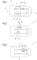
- Figures 1, 2, 3 , 4 and 5 each shows a schematic view of an electrical control system according to an exemplary embodiment.
- the electrical control system 1 is, for example, part of an electric vehicle charger 2.
- the electric vehicle charger 2 is connected, e.g. to a power source 4 being In particular an AC electrical grid. Further, the electric vehicle is configured to be connected to a charging cable 3 for charging and/or discharging an electric vehicle.
- the electrical control system 1 comprises a first contactor 5 connected to a first electrical conductive line 7 of a first type and a second contactor 6 connected to a second electrical conductive line 8 of a second type.
- the first type is of a positive polarity and the second type is of a negative polarity.
- the first contactor 5 is spaced apart from the second contactor 6 such that the two contactors are arranged close to one another physically. "Close to one another" means that the first contactor 5 and the second contactor 6 are positioned or located on the electrical conductive lines 7, 8 such that a distance between the contactors is minimized.
- the electric vehicle charger comprises a power conversion component.
- the first electrical conductive line 7 and the second electrical conductive line 8 are, for example, connected to the power conversion component, in particular to a first terminal and a second terminal of the power conversion component.
- a fuse 11 is connected to the first contactor 5 in series.
- the fuse 11 is located between the first contactor 5 and a side of the charging cable 3. This is that the fuse 11 faces the side of the charging cable 3.
- the electrical control system 1 comprises a circuit protection means.
- the circuit protection means comprises an enclosure 9 enclosing the first contactor 5 and the second contactor 6.
- the enclosure 9 completely encloses the first contactor 5 and the second contactor 6 in a three dimensionally.
- the enclosure 9 comprises an outer wall, which is completely penetrated by a plurality of recesses 17.
- the circuit protection means of the electrical control system 1 comprises in comparison to Figure 1 , a pyro-switch 13, a fuse 11 and a further pyro-switch 14.
- the pyro-switch 13 and the fuse 11 are connected in series.
- the pyro-switch 13 faces a side of the power source 4 and the fuse 11 faces a side of the charging cable 3. Further, the combination of the pyro-switch 13 and the fuse 11 arranged in series are connected in parallel to the first contactor 5.
- the pyro-switch 13 and the further pyro-switch 14 are each a normally open pyro-switch being configured to not transmit an electrical current until a threshold of the electrical current is exceeded.
- the further pyro-switch 14 is connected in parallel to the second contactor 6.
- the circuit protection means of the electrical control system 1 comprises in comparison to Figure 1 and Figure 2 , a pyro-switch 13 and a fuse 11.
- the pyro-switch 13 and the fuse 11 are connected in parallel.
- the combination of the pyro-switch 13 and the fuse 11 are connected in series to the first contactor 5.
- the combination of the pyro-switch 13 and the fuse 11 are located between the first contactor 5 and a side of the charging cable 3. This is that the pyro-switch 13 and the fuse 11 both face the side of the charging cable 3.
- the pyro-switch 13 is a normally closed pyro-switch configured to transmit an electrical current until a threshold of the electrical current is exceeded.
- the circuit protection means of the electrical control system 1 comprises in comparison to Figure 1, 2 and 3 , a pyro-switch 13, a fuse 11, a further pyro-switch 14 and a further fuse 12.
- the pyro-switch 13 and the fuse 11 are connected in series, forming a branch of the circuit protection means.
- the further pyro-switch 14 and the further fuse 12 are connected in series, forming a further branch of the circuit protection means.
- the branch connects the first electrical conductive line 7 and the second electrical conductive line 8 on a side facing the power source 4.
- the further branch connects the first electrical conductive line 7 and the second electrical conductive line 8 on a side facing the charging cable 3.
- the fuse 11 and the further fuse 12 face the first electrical conductive line 7 and the pyro switch and the further pyro-switch 14 face the second electrical conductive line 8.
- the pyro switch 13 and the further pyro-switch 14 are each a normally open pyro-switch being configured to not transmit an electrical current until a threshold of the electrical current is exceeded.
- the circuit protection means of the electrical control system 1 comprises in comparison to Figures 1, 2, 3 and 4 an enclosure 9 of Figure 1 and a further enclosure 10.
- the electrical control system 1 further comprises a third contactor 15 connected to the first electrical conductive line 7 and a fourth contactor 16 connected to the second electrical conductive line 8.
- the third contactor 15 is connected in series to the first contactor 5 and the fourth contactor 16 is connected in series to the second contactor 6.
- the third contactor 15 and the fourth contactor 16 both face the charging cable 3.
- the third contactor 15 is spaced apart from the fourth contactor 16 such that the two contactors are arranged close to one another physically. "Close to one another" means that the third contactor 15 and the fourth contactor 16 are positioned or located on the electrical conductive lines 7, 8 such that a distance between the contactors is minimized.
- the further enclosure 10 completely encloses the third contactor 15 and the fourth contactor 16.
- the further enclosure 10 completely encloses the third contactor 15 and the fourth contactor 16 in a three dimensionally.
- the further enclosure 10 comprises a further outer wall, which is completely penetrated by a plurality of recesses 17.
Landscapes
- Engineering & Computer Science (AREA)
- Power Engineering (AREA)
- Transportation (AREA)
- Mechanical Engineering (AREA)
- Life Sciences & Earth Sciences (AREA)
- Sustainable Development (AREA)
- Sustainable Energy (AREA)
- Electric Propulsion And Braking For Vehicles (AREA)
Priority Applications (3)
| Application Number | Priority Date | Filing Date | Title |
|---|---|---|---|
| EP23386054.3A EP4488099A1 (fr) | 2023-07-03 | 2023-07-03 | Système de commande électrique et chargeur de véhicule électrique |
| CN202480045148.9A CN121443475A (zh) | 2023-07-03 | 2024-06-20 | 电气控制系统和电动车辆充电器 |
| PCT/EP2024/067191 WO2025008188A1 (fr) | 2023-07-03 | 2024-06-20 | Système de commande électrique et chargeur de véhicule électrique |
Applications Claiming Priority (1)
| Application Number | Priority Date | Filing Date | Title |
|---|---|---|---|
| EP23386054.3A EP4488099A1 (fr) | 2023-07-03 | 2023-07-03 | Système de commande électrique et chargeur de véhicule électrique |
Publications (1)
| Publication Number | Publication Date |
|---|---|
| EP4488099A1 true EP4488099A1 (fr) | 2025-01-08 |
Family
ID=87378061
Family Applications (1)
| Application Number | Title | Priority Date | Filing Date |
|---|---|---|---|
| EP23386054.3A Pending EP4488099A1 (fr) | 2023-07-03 | 2023-07-03 | Système de commande électrique et chargeur de véhicule électrique |
Country Status (3)
| Country | Link |
|---|---|
| EP (1) | EP4488099A1 (fr) |
| CN (1) | CN121443475A (fr) |
| WO (1) | WO2025008188A1 (fr) |
Citations (4)
| Publication number | Priority date | Publication date | Assignee | Title |
|---|---|---|---|---|
| US3136922A (en) * | 1962-01-08 | 1964-06-09 | Irvin W Hynd | Electrical control systems |
| WO2015071712A1 (fr) * | 2013-11-14 | 2015-05-21 | Toyota Jidosha Kabushiki Kaisha | Système de charge et de décharge ayant un verrou de connecteur |
| US20150303737A1 (en) * | 2012-08-27 | 2015-10-22 | Aerovironment, Inc. | Portable Electric Vehicle Supply Equipment |
| WO2023095535A1 (fr) * | 2021-11-26 | 2023-06-01 | 株式会社オートネットワーク技術研究所 | Dispositif d'interruption |
Family Cites Families (2)
| Publication number | Priority date | Publication date | Assignee | Title |
|---|---|---|---|---|
| KR100627432B1 (ko) * | 2004-06-28 | 2006-09-25 | 타이코에이엠피 주식회사 | 릴레이의 접속장치 |
| EP4053874B1 (fr) * | 2021-03-01 | 2025-07-23 | Melexis Technologies SA | Contacteur, circuit intégré, procédé d'interruption d'un flux de courant |
-
2023
- 2023-07-03 EP EP23386054.3A patent/EP4488099A1/fr active Pending
-
2024
- 2024-06-20 WO PCT/EP2024/067191 patent/WO2025008188A1/fr not_active Ceased
- 2024-06-20 CN CN202480045148.9A patent/CN121443475A/zh active Pending
Patent Citations (4)
| Publication number | Priority date | Publication date | Assignee | Title |
|---|---|---|---|---|
| US3136922A (en) * | 1962-01-08 | 1964-06-09 | Irvin W Hynd | Electrical control systems |
| US20150303737A1 (en) * | 2012-08-27 | 2015-10-22 | Aerovironment, Inc. | Portable Electric Vehicle Supply Equipment |
| WO2015071712A1 (fr) * | 2013-11-14 | 2015-05-21 | Toyota Jidosha Kabushiki Kaisha | Système de charge et de décharge ayant un verrou de connecteur |
| WO2023095535A1 (fr) * | 2021-11-26 | 2023-06-01 | 株式会社オートネットワーク技術研究所 | Dispositif d'interruption |
Also Published As
| Publication number | Publication date |
|---|---|
| WO2025008188A1 (fr) | 2025-01-09 |
| CN121443475A (zh) | 2026-01-30 |
Similar Documents
| Publication | Publication Date | Title |
|---|---|---|
| US10026948B2 (en) | Safety element for battery cell | |
| EP2741391A2 (fr) | Bloc-batterie présentant une sécurité améliorée | |
| US9509132B2 (en) | Switching device for controlling energy supply of a downstream electric motor | |
| EP3652833B1 (fr) | Système de chargement | |
| CN109713190B (zh) | 一种具有两种输出类型的防爆锂电池电源及其工作方法 | |
| JP5990878B2 (ja) | 無停電電源装置及び電源装置 | |
| CN107370116A (zh) | 模块化电路保护系统和方法 | |
| AU2021310148B2 (en) | Explosion-proof battery pack | |
| CN113615024A (zh) | 具有增强的安全智能的危险场所合规的电路保护装置、系统和方法 | |
| CN103209853A (zh) | 用于从连接装置分离蓄电池的供电装置和方法以及机动车 | |
| US9735777B2 (en) | Disconnection of solar modules | |
| CN116978754A (zh) | 断路器和电力设备 | |
| KR20180118607A (ko) | 배터리 보호 디바이스 | |
| EP4488099A1 (fr) | Système de commande électrique et chargeur de véhicule électrique | |
| CN111095719B (zh) | 蓄电池装置 | |
| CN108269962B (zh) | 一种电池及电池保护装置 | |
| KR20150068845A (ko) | 전지 조립체 및 이를 포함하는 하이브리드 자동차 | |
| CN212991226U (zh) | 防爆电池 | |
| CN104810500A (zh) | 用于牵引电池组的电流中断装置 | |
| EP4354586A1 (fr) | Bloc-batterie | |
| CN116978753A (zh) | 断路器和电力设备 | |
| EP3726624A1 (fr) | Systeme de batterie et vehicule electrique | |
| KR102341490B1 (ko) | 전원스위치를 포함하는 고전력 파워뱅크 | |
| US11936221B2 (en) | Battery system, local electrical grid and disconnector | |
| WO2017158508A1 (fr) | Alarme incendie intelligente pour tableaux électriques basse tension |
Legal Events
| Date | Code | Title | Description |
|---|---|---|---|
| PUAI | Public reference made under article 153(3) epc to a published international application that has entered the european phase |
Free format text: ORIGINAL CODE: 0009012 |
|
| STAA | Information on the status of an ep patent application or granted ep patent |
Free format text: STATUS: THE APPLICATION HAS BEEN PUBLISHED |
|
| AK | Designated contracting states |
Kind code of ref document: A1 Designated state(s): AL AT BE BG CH CY CZ DE DK EE ES FI FR GB GR HR HU IE IS IT LI LT LU LV MC ME MK MT NL NO PL PT RO RS SE SI SK SM TR |
|
| STAA | Information on the status of an ep patent application or granted ep patent |
Free format text: STATUS: REQUEST FOR EXAMINATION WAS MADE |
|
| 17P | Request for examination filed |
Effective date: 20250708 |