EP4488407A1 - Dispositif d'alimentation d'une installation de revêtement en gaz de processus requis et procédé de fonctionnement d'un tel dispositif d'alimentation en gaz - Google Patents
Dispositif d'alimentation d'une installation de revêtement en gaz de processus requis et procédé de fonctionnement d'un tel dispositif d'alimentation en gaz Download PDFInfo
- Publication number
- EP4488407A1 EP4488407A1 EP24180511.8A EP24180511A EP4488407A1 EP 4488407 A1 EP4488407 A1 EP 4488407A1 EP 24180511 A EP24180511 A EP 24180511A EP 4488407 A1 EP4488407 A1 EP 4488407A1
- Authority
- EP
- European Patent Office
- Prior art keywords
- mfc
- gas
- condensation
- gases
- base
- Prior art date
- Legal status (The legal status is an assumption and is not a legal conclusion. Google has not performed a legal analysis and makes no representation as to the accuracy of the status listed.)
- Pending
Links
Images



Classifications
-
- C—CHEMISTRY; METALLURGY
- C23—COATING METALLIC MATERIAL; COATING MATERIAL WITH METALLIC MATERIAL; CHEMICAL SURFACE TREATMENT; DIFFUSION TREATMENT OF METALLIC MATERIAL; COATING BY VACUUM EVAPORATION, BY SPUTTERING, BY ION IMPLANTATION OR BY CHEMICAL VAPOUR DEPOSITION, IN GENERAL; INHIBITING CORROSION OF METALLIC MATERIAL OR INCRUSTATION IN GENERAL
- C23C—COATING METALLIC MATERIAL; COATING MATERIAL WITH METALLIC MATERIAL; SURFACE TREATMENT OF METALLIC MATERIAL BY DIFFUSION INTO THE SURFACE, BY CHEMICAL CONVERSION OR SUBSTITUTION; COATING BY VACUUM EVAPORATION, BY SPUTTERING, BY ION IMPLANTATION OR BY CHEMICAL VAPOUR DEPOSITION, IN GENERAL
- C23C16/00—Chemical coating by decomposition of gaseous compounds, without leaving reaction products of surface material in the coating, i.e. chemical vapour deposition [CVD] processes
- C23C16/44—Chemical coating by decomposition of gaseous compounds, without leaving reaction products of surface material in the coating, i.e. chemical vapour deposition [CVD] processes characterised by the method of coating
- C23C16/448—Chemical coating by decomposition of gaseous compounds, without leaving reaction products of surface material in the coating, i.e. chemical vapour deposition [CVD] processes characterised by the method of coating characterised by the method used for generating reactive gas streams, e.g. by evaporation or sublimation of precursor materials
- C23C16/4485—Chemical coating by decomposition of gaseous compounds, without leaving reaction products of surface material in the coating, i.e. chemical vapour deposition [CVD] processes characterised by the method of coating characterised by the method used for generating reactive gas streams, e.g. by evaporation or sublimation of precursor materials by evaporation without using carrier gas in contact with the source material
-
- C—CHEMISTRY; METALLURGY
- C23—COATING METALLIC MATERIAL; COATING MATERIAL WITH METALLIC MATERIAL; CHEMICAL SURFACE TREATMENT; DIFFUSION TREATMENT OF METALLIC MATERIAL; COATING BY VACUUM EVAPORATION, BY SPUTTERING, BY ION IMPLANTATION OR BY CHEMICAL VAPOUR DEPOSITION, IN GENERAL; INHIBITING CORROSION OF METALLIC MATERIAL OR INCRUSTATION IN GENERAL
- C23C—COATING METALLIC MATERIAL; COATING MATERIAL WITH METALLIC MATERIAL; SURFACE TREATMENT OF METALLIC MATERIAL BY DIFFUSION INTO THE SURFACE, BY CHEMICAL CONVERSION OR SUBSTITUTION; COATING BY VACUUM EVAPORATION, BY SPUTTERING, BY ION IMPLANTATION OR BY CHEMICAL VAPOUR DEPOSITION, IN GENERAL
- C23C16/00—Chemical coating by decomposition of gaseous compounds, without leaving reaction products of surface material in the coating, i.e. chemical vapour deposition [CVD] processes
- C23C16/04—Coating on selected surface areas, e.g. using masks
- C23C16/045—Coating cavities or hollow spaces, e.g. interior of tubes; Infiltration of porous substrates
-
- C—CHEMISTRY; METALLURGY
- C23—COATING METALLIC MATERIAL; COATING MATERIAL WITH METALLIC MATERIAL; CHEMICAL SURFACE TREATMENT; DIFFUSION TREATMENT OF METALLIC MATERIAL; COATING BY VACUUM EVAPORATION, BY SPUTTERING, BY ION IMPLANTATION OR BY CHEMICAL VAPOUR DEPOSITION, IN GENERAL; INHIBITING CORROSION OF METALLIC MATERIAL OR INCRUSTATION IN GENERAL
- C23C—COATING METALLIC MATERIAL; COATING MATERIAL WITH METALLIC MATERIAL; SURFACE TREATMENT OF METALLIC MATERIAL BY DIFFUSION INTO THE SURFACE, BY CHEMICAL CONVERSION OR SUBSTITUTION; COATING BY VACUUM EVAPORATION, BY SPUTTERING, BY ION IMPLANTATION OR BY CHEMICAL VAPOUR DEPOSITION, IN GENERAL
- C23C16/00—Chemical coating by decomposition of gaseous compounds, without leaving reaction products of surface material in the coating, i.e. chemical vapour deposition [CVD] processes
- C23C16/22—Chemical coating by decomposition of gaseous compounds, without leaving reaction products of surface material in the coating, i.e. chemical vapour deposition [CVD] processes characterised by the deposition of inorganic material, other than metallic material
- C23C16/30—Deposition of compounds, mixtures or solid solutions, e.g. borides, carbides, nitrides
- C23C16/40—Oxides
- C23C16/401—Oxides containing silicon
- C23C16/402—Silicon dioxide
-
- C—CHEMISTRY; METALLURGY
- C23—COATING METALLIC MATERIAL; COATING MATERIAL WITH METALLIC MATERIAL; CHEMICAL SURFACE TREATMENT; DIFFUSION TREATMENT OF METALLIC MATERIAL; COATING BY VACUUM EVAPORATION, BY SPUTTERING, BY ION IMPLANTATION OR BY CHEMICAL VAPOUR DEPOSITION, IN GENERAL; INHIBITING CORROSION OF METALLIC MATERIAL OR INCRUSTATION IN GENERAL
- C23C—COATING METALLIC MATERIAL; COATING MATERIAL WITH METALLIC MATERIAL; SURFACE TREATMENT OF METALLIC MATERIAL BY DIFFUSION INTO THE SURFACE, BY CHEMICAL CONVERSION OR SUBSTITUTION; COATING BY VACUUM EVAPORATION, BY SPUTTERING, BY ION IMPLANTATION OR BY CHEMICAL VAPOUR DEPOSITION, IN GENERAL
- C23C16/00—Chemical coating by decomposition of gaseous compounds, without leaving reaction products of surface material in the coating, i.e. chemical vapour deposition [CVD] processes
- C23C16/44—Chemical coating by decomposition of gaseous compounds, without leaving reaction products of surface material in the coating, i.e. chemical vapour deposition [CVD] processes characterised by the method of coating
- C23C16/455—Chemical coating by decomposition of gaseous compounds, without leaving reaction products of surface material in the coating, i.e. chemical vapour deposition [CVD] processes characterised by the method of coating characterised by the method used for introducing gases into reaction chamber or for modifying gas flows in reaction chamber
- C23C16/45512—Premixing before introduction in the reaction chamber
-
- C—CHEMISTRY; METALLURGY
- C23—COATING METALLIC MATERIAL; COATING MATERIAL WITH METALLIC MATERIAL; CHEMICAL SURFACE TREATMENT; DIFFUSION TREATMENT OF METALLIC MATERIAL; COATING BY VACUUM EVAPORATION, BY SPUTTERING, BY ION IMPLANTATION OR BY CHEMICAL VAPOUR DEPOSITION, IN GENERAL; INHIBITING CORROSION OF METALLIC MATERIAL OR INCRUSTATION IN GENERAL
- C23C—COATING METALLIC MATERIAL; COATING MATERIAL WITH METALLIC MATERIAL; SURFACE TREATMENT OF METALLIC MATERIAL BY DIFFUSION INTO THE SURFACE, BY CHEMICAL CONVERSION OR SUBSTITUTION; COATING BY VACUUM EVAPORATION, BY SPUTTERING, BY ION IMPLANTATION OR BY CHEMICAL VAPOUR DEPOSITION, IN GENERAL
- C23C16/00—Chemical coating by decomposition of gaseous compounds, without leaving reaction products of surface material in the coating, i.e. chemical vapour deposition [CVD] processes
- C23C16/44—Chemical coating by decomposition of gaseous compounds, without leaving reaction products of surface material in the coating, i.e. chemical vapour deposition [CVD] processes characterised by the method of coating
- C23C16/455—Chemical coating by decomposition of gaseous compounds, without leaving reaction products of surface material in the coating, i.e. chemical vapour deposition [CVD] processes characterised by the method of coating characterised by the method used for introducing gases into reaction chamber or for modifying gas flows in reaction chamber
- C23C16/45561—Gas plumbing upstream of the reaction chamber
-
- C—CHEMISTRY; METALLURGY
- C23—COATING METALLIC MATERIAL; COATING MATERIAL WITH METALLIC MATERIAL; CHEMICAL SURFACE TREATMENT; DIFFUSION TREATMENT OF METALLIC MATERIAL; COATING BY VACUUM EVAPORATION, BY SPUTTERING, BY ION IMPLANTATION OR BY CHEMICAL VAPOUR DEPOSITION, IN GENERAL; INHIBITING CORROSION OF METALLIC MATERIAL OR INCRUSTATION IN GENERAL
- C23C—COATING METALLIC MATERIAL; COATING MATERIAL WITH METALLIC MATERIAL; SURFACE TREATMENT OF METALLIC MATERIAL BY DIFFUSION INTO THE SURFACE, BY CHEMICAL CONVERSION OR SUBSTITUTION; COATING BY VACUUM EVAPORATION, BY SPUTTERING, BY ION IMPLANTATION OR BY CHEMICAL VAPOUR DEPOSITION, IN GENERAL
- C23C16/00—Chemical coating by decomposition of gaseous compounds, without leaving reaction products of surface material in the coating, i.e. chemical vapour deposition [CVD] processes
- C23C16/44—Chemical coating by decomposition of gaseous compounds, without leaving reaction products of surface material in the coating, i.e. chemical vapour deposition [CVD] processes characterised by the method of coating
- C23C16/52—Controlling or regulating the coating process
-
- C—CHEMISTRY; METALLURGY
- C23—COATING METALLIC MATERIAL; COATING MATERIAL WITH METALLIC MATERIAL; CHEMICAL SURFACE TREATMENT; DIFFUSION TREATMENT OF METALLIC MATERIAL; COATING BY VACUUM EVAPORATION, BY SPUTTERING, BY ION IMPLANTATION OR BY CHEMICAL VAPOUR DEPOSITION, IN GENERAL; INHIBITING CORROSION OF METALLIC MATERIAL OR INCRUSTATION IN GENERAL
- C23C—COATING METALLIC MATERIAL; COATING MATERIAL WITH METALLIC MATERIAL; SURFACE TREATMENT OF METALLIC MATERIAL BY DIFFUSION INTO THE SURFACE, BY CHEMICAL CONVERSION OR SUBSTITUTION; COATING BY VACUUM EVAPORATION, BY SPUTTERING, BY ION IMPLANTATION OR BY CHEMICAL VAPOUR DEPOSITION, IN GENERAL
- C23C16/00—Chemical coating by decomposition of gaseous compounds, without leaving reaction products of surface material in the coating, i.e. chemical vapour deposition [CVD] processes
- C23C16/44—Chemical coating by decomposition of gaseous compounds, without leaving reaction products of surface material in the coating, i.e. chemical vapour deposition [CVD] processes characterised by the method of coating
- C23C16/54—Apparatus specially adapted for continuous coating
-
- G—PHYSICS
- G01—MEASURING; TESTING
- G01F—MEASURING VOLUME, VOLUME FLOW, MASS FLOW OR LIQUID LEVEL; METERING BY VOLUME
- G01F22/00—Methods or apparatus for measuring volume of fluids or fluent solid material, not otherwise provided for
- G01F22/02—Methods or apparatus for measuring volume of fluids or fluent solid material, not otherwise provided for involving measurement of pressure
-
- G—PHYSICS
- G01—MEASURING; TESTING
- G01F—MEASURING VOLUME, VOLUME FLOW, MASS FLOW OR LIQUID LEVEL; METERING BY VOLUME
- G01F25/00—Testing or calibration of apparatus for measuring volume, volume flow or liquid level or for metering by volume
- G01F25/10—Testing or calibration of apparatus for measuring volume, volume flow or liquid level or for metering by volume of flowmeters
- G01F25/15—Testing or calibration of apparatus for measuring volume, volume flow or liquid level or for metering by volume of flowmeters specially adapted for gas meters
-
- G—PHYSICS
- G01—MEASURING; TESTING
- G01F—MEASURING VOLUME, VOLUME FLOW, MASS FLOW OR LIQUID LEVEL; METERING BY VOLUME
- G01F25/00—Testing or calibration of apparatus for measuring volume, volume flow or liquid level or for metering by volume
- G01F25/10—Testing or calibration of apparatus for measuring volume, volume flow or liquid level or for metering by volume of flowmeters
- G01F25/17—Testing or calibration of apparatus for measuring volume, volume flow or liquid level or for metering by volume of flowmeters using calibrated reservoirs
-
- G—PHYSICS
- G01—MEASURING; TESTING
- G01F—MEASURING VOLUME, VOLUME FLOW, MASS FLOW OR LIQUID LEVEL; METERING BY VOLUME
- G01F25/00—Testing or calibration of apparatus for measuring volume, volume flow or liquid level or for metering by volume
- G01F25/0092—Testing or calibration of apparatus for measuring volume, volume flow or liquid level or for metering by volume for metering by volume
Definitions
- the invention relates to a device according to the preamble of claim 1, in particular the invention relates to a device for supplying a system for coating workpieces with process gases required for the coating process taking place on the system, in particular for coating the inner walls of containers.
- These containers are preferably bottles, in particular containers or bottles made of plastic, e.g. made of PET.
- the coating system preferably carries out the coating using a PECVD process, in particular using a microwave-induced PECVD process.
- the invention also relates to a coating system with such a gas supply device.
- the invention further relates to a method according to the preamble of claim 10, in particular the invention relates to a method for operating a device for supplying a system for coating workpieces as mentioned above with process gases required for the coating process.
- the invention concerns the supply of systems for coating inner walls of containers, in particular bottles, in particular by means of a PECVD method, in particular by means of a microwave-induced PECVD method.
- the present invention focuses particularly on the coating of containers, e.g. bottles, in particular on the inner coating of containers, in particular by so-called PECVD processes, which are basically known in the prior art, e.g. from WO03/100125 A1 , the WO03/100121 A2 or the WO03/100120 A2
- PECVD processes which are basically known in the prior art, e.g. from WO03/100125 A1 , the WO03/100121 A2 or the WO03/100120 A2
- the description of the invention is primarily made with regard to these PECVD processes and with regard to the internal coating of containers, e.g. made of PET, without any intended or associated limitation.
- These PECVD processes and systems on which such PECVD processes are carried out are also known in the prior art and do not require a detailed description.
- process gases are fed into mixing agents in metered form.
- mixing agents can be, for example, simple intersection points of converging lines, or they can be pipe sections with an enlarged diameter into which supply lines flow.
- the metering is carried out by MFCs, which are arranged in lines for those basic gases that are to be combined and mixed with other basic gases to form gas mixtures.
- MFCs are usually calibrated to a specific control range and for a specific gas.
- the dosing accuracy of an MFC can decrease over time, or the calibration of an MFC can lose its validity over time. It is therefore fundamentally possible that the dosing performance once set no longer applies over time without being noticed, and the gas mixture obtained no longer corresponds to the intended composition, so that the resulting coating no longer corresponds to the intended coating quality. It would be fundamentally possible to check the quality of the coatings using measurement technology, e.g. optically, and to adjust the dosing to the MFC. It would also be fundamentally possible to carry out an examination of the gas mixtures obtained and to derive changes to the MFC from this and to readjust them. It is also conceivable, for example, to recalibrate the MFC at regular intervals. However, all of these options represent a very high expenditure.
- the invention is therefore based on the object of providing an improved solution which addresses the problems mentioned.
- the object of the present invention is to provide a device of the type mentioned in the introduction in such a way that the dosing of MFC can be improved in qualitative terms.
- advantages are to be achieved in the monitoring of devices for the provision of process gases.
- the object is achieved by a device having the characterizing features of device claim 1.
- the device for supplying a coating system with the process gases required for coating processes taking place on the system.
- the device has at least two base gas lines. These base gas lines serve to guide at least two base gases separately in one flow direction.
- Mixing means are also provided for combining and mixing at least two of the base gases to form a gas mixture.
- the base gases themselves can already be a mixture.
- the designation as base gas means that starting gases are present in the mixing means before mixing and these are only combined in the mixing means to form gas mixtures that are used for a subsequent coating process.
- Typical base gases can be, for example, oxygen, nitrogen or argon, which are already present as gas and are supplied from a gas source.
- the base gas can also be created by evaporating liquid components, e.g. by evaporating HMDSN and/or HMDSO.
- MFCs are arranged in the base gas lines that lead to the mixing agent. These MFCs are arranged in front of the mixing agent in the direction of flow and thus ensure a metered supply of the base gases to the mixing agent.
- the device for providing a first base gas has at least one evaporator.
- This evaporator is set up and designed to convert a liquid starting fluid into the gaseous state.
- the evaporator has in particular heating means for heating the starting fluid at least up to its boiling temperature, so that the liquid starting fluid can be converted into the gaseous state.
- the heating means are controlled or regulated, for example, in such a way that a certain temperature of the starting fluid is constantly reached. Evaporators of this type or similar types are known in the prior art.
- the corresponding associated MFC is also kept at a temperature greater than or equal to the boiling temperature of the liquid starting fluid, so that this MFC can meter the base gas produced in the evaporator to the mixing agent without condensation of the gas affecting this metering.
- the said MFC is kept at a temperature several °C, e.g. 5 °C, higher than the boiling temperature.
- the device according to the invention has a reference device that provides a reference volume of known size.
- the reference device is also kept at a temperature that prevents condensation and is greater than or equal to the boiling temperature; this temperature is, for example, identical to the temperature at which the MFC is kept.
- the purpose of the arrangement and the presence of the reference device is to check the proper functioning of the MFC or, if necessary, several MFCs.
- MFCs are usually calibrated to a specific control range for a specific gas.
- a so-called pressure increase test can be carried out with the help of the reference device, from which the actual gas quantity per unit of time that the tested MFC makes available can then be calculated.
- the reference device therefore has a pressure sensor for detecting the pressure in the reference volume, whereby the reference volume is fed to the pressure sensor via a pump line controlled by a switchable valve.
- a pump device for generating a negative pressure in the reference volume is connected, and wherein the MFC, which is kept at the condensation-preventing temperature, is connected to the reference volume via a reference line controlled by a switchable valve.
- This reference line is designed at least partially independently of the base gas lines and is preferably arranged behind the MFC and before the mixing medium in the flow direction of the supplied base gases, e.g. by the reference line branching off from the base gas line between the MFC and the mixing medium.
- a pressure increase test can be carried out, for example, at fixed intervals or on specific occasions. It is also possible for such a pressure increase test to be triggered by an operator, for example because the quality of the coatings obtained indicates a problem in the coating system.
- Such a pressure increase test can be as follows to check an MFC.
- the reference volume is first pumped out by the pumping device to a certain negative pressure. To do this, the valve controlling the pump line is switched to the open position, while all other lines to the reference volume are closed.
- the pressure in the reference volume is measured, for example, by a pressure cell as a pressure sensor. If the pressure in the reference volume has reached a specified negative pressure value, for example, or if the reference volume has been connected to the pumping device for a certain period of time, the valve in the pump line closes. Gas is then fed through the MFC to be tested along the reference line and into the reference volume with the switching valve in the reference line open.
- No other line leading to the reference volume is open, so that any pressure change in the reference volume is caused exclusively by inflowing gas that is metered in via the MFC to be tested.
- the pressure in the reference volume is measured and recorded over time.
- the pressure curve can be used to determine which volume flowed into the test volume per time, so that the actual flow through the MFC can also be determined. If this determined actual flow matches the target flow set on the MFC, the MFC is working properly along the original calibration, otherwise readjustment is required.
- the precision of such a pressure increase test can optionally be improved if a leak rate is determined beforehand. Similar to the pressure increase test, after pumping out, the pressure increase in the reference volume without gas inflow is observed and evaluated for a certain period of time. The leak flow calculated in this way is then subtracted from the MFC flow determined later in order to obtain the real flow through the MFC.
- Such a pressure increase test can be carried out using the same reference volume for several MFCs if several MFCs are connected to the same reference volume via corresponding reference lines.
- the test described above can therefore be carried out for several MFCs one after the other. If several reference volumes are provided, the test described above can be carried out in parallel using these several reference volumes if the assignment of a specific MFC to a reference volume via a specific reference line is guaranteed, i.e. only one MFC is connected to a single reference volume at a time, and a measured pressure increase can be clearly compared to a specific MFC and its dosing.
- this reference device with a known reference volume is that it can be checked whether the MFC is still metering the base gases in the originally calibrated manner without having to remove the MFC and/or recalibrate it.
- the advantage of also keeping the reference device at a temperature that prevents condensation is that it provides greater measurement accuracy, because otherwise condensation processes would distort the pressure increase test.
- a sensible and therefore preferred size for the reference volume depends on several factors.
- the reference volume should enable a pressure increase measurement, so the reference volume should lead to a sensible measuring range. This depends on a typical flow through the MFC that is to be tested. If this flow is large, the test volume should also be relatively large in order to be able to measure a pressure change over a sufficiently long time during the pressure increase test. If the flow rate through the MFC is small, this would also be possible with a smaller volume. If only a single reference volume is to be provided for several MFCs with different flow rates, this volume must be a compromise that still leads to a sensible measuring range for all MFCs.
- the expert can choose a suitable volume without any problems and the expert recognizes that a suitable volume can still be selected within wide limits.
- a reference volume of 5 liters is a suitable size, but a smaller volume of eg 1 liter or a larger volume of eg 10 liters still result in a reasonable measuring range, eg for MFC between 100 sccm up to several 1000 sccm.
- the specific choice of the size of the reference volume also depends on how precise the pressure increase test should be and how much time can be made available for such a pressure increase test.
- Such a pressure increase test can be carried out, for example, at fixed events, for example every time the device according to the invention is started.
- the test can also be carried out, for example, when there are interruptions in production. It is also conceivable that a test is carried out as soon as a certain production operating time is reached, e.g. every 12 production hours. If necessary, this achievement could also be displayed to an operator and this operator can then trigger the test as soon as a suitable time is reached. It is also conceivable that an operator always carries out such a test when the operator considers it useful. Other event-oriented or other time-oriented triggers for pressure increase tests are conceivable.
- the result of the test could, for example, simply be displayed to an operator; it is also possible to record the results, e.g. as a quality statement that the process gases provided were of a certain composition quality. It is also conceivable that if a deviation is detected in the test, e.g. a deviation that exceeds certain tolerance limits, a warning is issued or displayed and, for example, an intervention is indicated as necessary. It is also conceivable that a setting on an MFC is automatically adjusted to eliminate the deviation. If the test shows, for example, that an MFC is dosing too small a quantity, the opening cross-section on the MFC could be increased.
- a further object of the present invention is in particular to develop a method of the type mentioned in the introduction. Advantages are to be achieved in the provision of process gases, in particular in the metered supply of base gases for generating the process gases.
- this object is achieved by a method having the characterizing features of method claim 10.
- the device has two or more evaporators for providing two or more base gases, each of which is set up and designed to convert a liquid starting fluid into the gaseous state.
- the respective evaporators have, in a known manner, in particular heating means for heating the respective starting fluid at least to the respective boiling point.
- At least one MFC is assigned to each of these base gases created from liquid starting fluids, each of which is connected to a reference device with the properties of the characterizing part of claim 1. This includes the possibility of several reference devices being provided, e.g. one assigned reference device per MFC. This means that all MFCs could be checked simultaneously in the manner described above.
- MFCs are assigned to the same reference device and connected to it, so that the several MFCs can be checked one after the other in the manner described above. It is also possible for several reference devices to be provided and yet several MFCs are assigned to each reference device or connected to it. For example, a distinction could be made as to whether an MFC doses a base gas created from a liquid starting fluid (MFC of the first type) or doses a base gas already provided in gaseous form (MFC of the second type), and a reference device is provided for one type of MFC and a reference device for the other type of MFC. This would be advantageous in that the reference device assigned to the base gases already supplied in gaseous form is unproblematic with regard to condensation and therefore does not have to be kept at an elevated temperature to avoid condensation.
- the reference device should preferably be brought to at least the higher of the boiling temperatures, if necessary a few degrees higher, e.g. 5 °C higher.
- Maintaining the MFC and/or the reference device at a temperature that prevents condensation could be carried out in such a way that tempering devices are assigned to each one, so that the MFC is tempered and the reference device is tempered. If several reference devices are to be tempered, each could be provided with a tempering device and each could be tempered individually. However, it is preferred that the device has a warm area surrounded by walls that is kept at a temperature that prevents condensation greater than or equal to the boiling temperature. If there is more than one boiling temperature that needs to be taken into account, the reference device should preferably be brought to at least the higher of the boiling temperatures, so the warm area should also be brought to at least the higher of the boiling temperatures, possibly a few degrees higher, e.g. 5 °C higher.
- all the elements to be tempered can be kept together at a temperature that prevents condensation by tempering the warm area and keeping it at a temperature that prevents condensation. This is preferable to individual temperature control of the affected MFC and/or reference devices.
- a base gas provided from a gas source is metered in by an MFC
- the installation space of the warm area can be reduced in this way.
- MFCs to be tempered should be assigned to a reference device to be tempered and MFCs not to be tempered should be assigned to a reference device not to be tempered. Accordingly, the MFC and the associated reference device should both be arranged inside or both outside the warm area.
- An MFC or a reference device are said to be tempered if they are to be brought to a temperature that prevents condensation. "Tempering" means setting a temperature by heating that prevents such condensation.
- control electronics of MFCs that are to be brought to a temperature that prevents condensation and that are therefore arranged in a warm area, for example, are arranged outside the warm area.
- the control electronics are designed without temperature control because they are arranged away from the tempered MFCs. This measure increases the service life of the corresponding control electronics and enables the use of control electronics that do not have to be designed for use in a warm area, thereby increasing the costs.
- the evaporator or each of the evaporators is designed to heat the starting fluid to at least 10 °C, preferably at least 15 °C and more preferably at least 20 °C above its boiling temperature, wherein the condensation-preventing temperature in the warm range is preferably kept at least 5 °C above this heating temperature.
- a device according to the invention can, for example, be designed and configured to carry out one of the methods specified in the method claims.
- a preferred application of a device according to the invention is in systems for coating workpieces, in particular for coating the inner walls of containers, in particular bottles.
- the inner coating of bottles made of a plastic is envisaged, in particular a thermoplastic, in particular PET.
- Coatings are preferably deposited on the system using a PECVD process, in particular using a microwave-induced PECVD process.
- PECVD process in particular using a microwave-induced PECVD process.
- An advantageous embodiment of a method according to the invention provides, for example, that the gas supply device is operated in at least two different operating modes according to any of the above variants.
- a first operating mode is a production mode in which the reference device or devices are not supplied with gas, but workpieces are coated. Accordingly, valves leading to the reference device are closed so that no gas reaches the reference device via reference lines.
- a second operating mode is a reference mode in which no workpieces are coated, but the reference device is supplied with gas, in that the reference lines leading thereto are no longer permanently closed, but are opened and closed in a suitable manner to carry out a pressure increase measurement.
- the pump device is also temporarily connected to the reference device and a negative pressure is set in the reference device. It is possible that this connection also exists in production mode or that a negative pressure is already set in the reference device in production mode with the advantage that a pressure increase measurement can be carried out immediately when switching to reference mode, since negative pressure conditions already exist in the reference device.
- the device according to the invention enables a method variant in which the volumes of the process gas lines leading to the coating system, and possibly also lines in the system leading to the coating chambers, are determined by carrying out a pressure increase measurement in process gas lines closed to the coating chambers.
- This requires pressure sensors that can record the pressure in process gas lines.
- negative pressure conditions are required in these process gas lines.
- opening and closing the appropriate valves it must be ensured that only gas flows into the process gas lines to be tested via a specific MFC into a closed volume and that this MFC has a known flow rate, e.g. previously determined by calibration or a previously carried out pressure increase measurement into a reference device.
- the volume determined in this way can, for example, be compared with an earlier measurement of this kind, in particular with a measurement when the system was commissioned or set up. In this way, it can be determined whether process gas-carrying lines reach critical levels of contamination due to separation processes and whether, for example, a cleaning process for the lines is required.
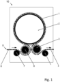
- a coating system more precisely a PECVD system 10, can be seen, which is provided with a rotating plasma wheel 2.
- a plurality of plasma stations 1 are arranged at a distance from one another along the circumference of the plasma wheel 2.
- the plasma stations 1 are provided with cavities or plasma chambers 17, shown later, for receiving workpieces 5 to be treated.
- each plasma station has four treatment stations.
- This PCVD system 10 is purely exemplary for all coating systems that carry out coating processes by supplying process gases.
- the workpieces are formed by containers only as an example below.
- the containers 5 to be treated are fed to the plasma wheel 2 in the area of an input 8 and forwarded via a separating wheel 7 to a transfer wheel 6, which is equipped with support arms that can be designed to be positionable, for example.
- the support arms can be arranged so that they can be pivoted relative to a base of the transfer wheel 6, for example, so that the distance between the containers 5 can be changed relative to one another.
- This transfers the containers 5 from the transfer wheel 6 to the plasma wheel 2.
- the treated containers 5 are removed from the area of the plasma wheel 2 by an output wheel 3 and transferred to the area of an output section 4.
- the containers 5 could, for example, be fed into the area of the input 8 with the mouth area facing upwards and, for example, the container 5 could be turned on the transfer wheel 6 into a position with the mouth area facing downwards.
- Work wheels with such a turning function are known in the prior art. In this position, the containers 5 would be transferred to the plasma wheel 2 and also removed from the plasma wheel 2 after treatment. The output wheel 3 could then turn the container 5 again and the container 5 could then be coated with a positioning with the mouth pointing upwards to the output section 4.
- the following figures show a positioning of the container 5 with the mouth area pointing downwards. It is of course also possible for the treatment to take place on the plasma wheel with the mouth area pointing upwards and for no turning process to be carried out before and after the plasma wheel.
- the plasma stations 1 rotating with the plasma wheel 2 are supplied with the process gases required for the coating process.
- the supply usually takes place in a center of the plasma wheel 2 and via a rotary distributor arranged there, via which the plasma stations 1 are also supplied with other operating materials and energy. Ring lines are used in particular for the distribution of operating materials.
- the process gases transferred to the plasma wheel 2 are in the required composition when transferred and are provided by a gas supply device arranged outside the plasma wheel 2, which will be described later and which represents the actual subject matter of the invention.
- FIG. 2 To explain a possible basic structure of a plasma station 1, a station with a single treatment station is shown in perspective.
- a station frame 16 is provided with guide rods 23 on which a carriage 24 is guided to hold the cylindrical chamber wall 18.
- Fig. 2 shows the carriage 24 with chamber wall 18 in a raised state, so that the upside-down workpiece in the form of a container 5 is released.
- a microwave generator 19 is arranged in the upper area of the plasma station 1.
- the microwave generator 19 is connected via a deflection 25 and an adapter 26 to a coupling channel 27 which opens into the plasma chamber 17.
- the adapter 26 has the function of a transition element.
- the deflection 25 is designed as a waveguide.
- the container 5 is positioned in the area of a sealing element 28 which is arranged in the area of a chamber floor 29.
- the chamber floor 29 is designed as part of a chamber base 30.
- the carriage 24 with the cylindrical chamber wall 18 can be lowered along the rails 23 until the chamber wall 18 has moved against the chamber floor 29.
- the plasma coating of the container 5, which is then enclosed in the closed cavity 17, can be carried out.
- the setting of the negative pressure required in the chamber 17 and in the container 5 also takes place. to generate a plasma and to carry out the microwave-induced plasma coating.
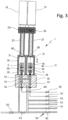
- Fig. 3 shows an alternative example of a plasma station 1 with two plasma chambers 17 for the simultaneous plasma treatment of two containers 5.
- Each of the plasma chambers 17 is connected to a microwave generator 19 via a coupling channel 27 as well as an adapter 26 and a deflection 25.
- a common microwave generator 19 for two or more plasma chambers 17 and to divide the generated microwave radiation via a branch (not shown) in order to ensure uniform ignition of the plasma in each of the plasma chambers 17.
- Coupling channels 54 open into the plasma chambers 17, each of which is connected to a branch 55 for dividing a quantity of a supplied operating medium into two partial quantities. If more than two plasma chambers 17 are used, the branch 55 is either provided with a corresponding number of outlets, or several partial branches are arranged in a cascade one behind the other. Negative pressure, for example, can be supplied via these channels 54, 55.
- a gas lance 36 that can be moved into and out of the container 5 in a vertical direction, e.g. in a manner not shown by being arranged on a lance carriage that can be guided in a vertical direction and, e.g., can perform a vertical movement in a curve-controlled manner.
- the plasma chamber 17 is closed and the lance 36 is arranged inside the container 5 for discharging the process gases into the interior of the container 5.
- the plasma chambers 17 and the containers 5 are subjected to negative pressure via the previously mentioned channels 54, 55.
- Process gases are fed to the gas lance 36 via a line 66 and guided into the interior of the container.
- the supply of all these operating materials is valve-controlled.
- the line 66 is connected to a gas supply device and guides the process gases provided by this gas supply device to the gas lance 36.
- Fig. 3 shows the control of a supply of operating materials in a highly schematic representation and with additional representation of valves 59.
- three branches 55 are used due to the circuit arrangement of the coupling channels 54.
- quartz glass windows 68 for sealing the interiors of the plasma chambers 17 relative to the interiors of the coupling channels 27 while simultaneously allowing the microwave radiation to pass through.
- a primary vacuum valve 60 is used to supply a first vacuum level and a secondary vacuum valve 61 is used to supply a vacuum that is lower than the first vacuum level.
- the addition of further vacuum levels is possible.
- a process vacuum valve 62 is also arranged. The process vacuum valve 62 prevents the extracted process gas from passing into the supply circuits for the primary vacuum and the secondary vacuum.
- a chamber vacuum valve 63 which performs a corresponding shut-off function.
- the idea is to supply the respective supply vacuum directly to the interior of the container 5 via the valves 60, 61, 62 and to switch on the further interior of the plasma chamber 17 as required, controlled by the chamber vacuum valve 63.
- a container vent valve 64 and a chamber vent valve 65 are used for a predeterminable and independent venting of both the interior of the container 5 and the further interior of the plasma chamber 17.
- a primary process gas valve 66 and a secondary process gas valve 67 are used to supply different process gas compositions. It is also conceivable to supply further process gas mixtures, so that further lines and further valves could be added.
- the process gas mixtures are provided by a gas supply device.
- a typical treatment process is carried out in such a way that first the container 5 is Figure 1 explained is transported to the plasma wheel 2 and the insertion of the container 5 into the plasma station 1 takes place in a pushed-up state of the sleeve-like chamber wall 18. After completion of the insertion process, the chamber wall 18 is lowered into its sealed position and initially an evacuation of both the cavity 17 and an interior of the container 5 carried out, if necessary, only a pre-evacuation of the cavity 17 is carried out before the evacuation of the interior of the container 5 is switched on.
- the lance 36 is moved into the interior of the container 5 and the interior of the container 5 is sealed off from the interior of the cavity 17. It is also possible to move the lance 36 into the container 5 synchronously with the beginning of the evacuation of the interior of the cavity 17. The pressure in the interior of the container 5 is then reduced even further. In addition, it is also planned to carry out the positioning movement of the lance 36 at least partially parallel to the positioning of the chamber wall 18. After a sufficiently low negative pressure has been reached, process gas is introduced into the interior of the container 5 and the plasma is ignited with the help of the microwave generator 19. In particular, it is planned to use the plasma to deposit both an adhesion promoter on an inner surface of the container 5 and the actual barrier layer of silicon oxides. An additional third layer, for example a protective layer, could also be deposited using the plasma, e.g. also made of silicon oxides.
- the lance 36 is removed from the interior of the container 5 and the plasma chamber 17 and the interior of the container 5 are ventilated.
- the chamber wall 18 is raised again in order to remove the coated container 5 and insert a new container 5 to be coated.
- the coating process described takes place while the container 5 rotates on the plasma wheel 2 in the plasma station 1.
- the chamber wall 18 and/or the lance 36 can be positioned using different drive units.
- the use of pneumatic drives and/or electric drives, in particular in an embodiment as a linear motor, is conceivable.
- it is intended to implement a cam control to support exact movement coordination with a rotation of the plasma wheel 2.
- the cam control can, for example, be designed in such a way that control cams are arranged along a circumference of the plasma wheel 2, along which cam rollers are guided. The cam rollers are coupled to the components to be positioned.
- the valves 59 are preferably operated via a programmable electronic control.
- the primary vacuum valve 60 is opened and the interior of the container 5 and the interior of the plasma chamber 17 are evacuated simultaneously or partially at different times. In this case, a pressure level in the range of 20 mbar to 50 mbar is reached.
- the secondary vacuum valve 61 is opened and the interior of the container 5 and the interior of the plasma chamber 17 are initially simultaneously connected to a vacuum source with a lower pressure level.
- the chamber vacuum valve 63 closes and only the interior of the workpiece 5 is further evacuated. In this case, a pressure level of approximately 0.1 mbar is reached.
- the primary process gas valve 66 After closing the chamber vacuum valve 63 and generally already previously positioning the lance 36 within the interior of the container 5, the primary process gas valve 66 opens and a process gas of a first composition is supplied. After sufficient process gas has been supplied, the microwave generator 19 ignites the plasma in the interior of the container 5. At a predeterminable point in time, the primary process gas valve 66 closes and the secondary process gas valve 67 opens to supply a process gas of a second composition. At least temporarily, parallel to the opening of the process gas valves 66, 67, the process vacuum valve 62 also opens in order to maintain a sufficiently low negative pressure in the interior of the container 5. A pressure level of, for example, about 0.3 mbar proves to be expedient here.
- the container vent valve 64 opens first and connects the interior of the container 5 to an ambient pressure. With a predeterminable time delay after the container vent valve 64 has opened, the chamber vent valve 65 also opens in order to raise the interior of the plasma chamber 17 back to the ambient pressure. After the ambient pressure within the plasma chamber 17 has at least approximately been reached, the plasma chamber 17 can open and the coated container 5 is removed and replaced with a new container 5 to be coated.
- FIG. 4 shows an exemplary appearance and an exemplary structure of such a gas supply device 100.
- Figure 5 shows in a schematic diagram which processes take place in such a gas supply device 100 and how an arrangement of lines and metering devices used for this purpose is advantageously carried out.
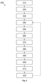
- Figure 6 shows a schematic diagram of a process sequence according to the invention of a Pressure rise measurement which can be carried out in a gas supply device designed according to the invention.
- the gas supply device 100 shown is designed in the form of a cabinet with side and rear walls and with cabinet doors in the front area, which are not shown, to allow a view into the interior of the device. These walls therefore delimit chambers or sub-chambers of the gas supply device 100. Lines run in these chambers and devices of the gas supply device are arranged, e.g. devices for guiding base gases, for controlling the flow of the gases by means of valves, for metering base gases by means of MFC, for mixing base gases with one another in mixing devices and/or for generating base gases in evaporators from precursor liquids.
- the gas supply cabinet 100 is divided vertically into a lower cabinet area 110 and an upper cabinet area 120.
- the lower cabinet area 110 in the embodiment shown, four barrels 112, 114 filled with a precursor fluid are arranged, which are separated from each other by vertical walls in the example shown.
- the two barrels 112 shown on the left side of the illustration are intended to contain HMDSN, for example, and the two barrels 114 shown on the right side of the illustration are intended to contain HMDSO, for example. All barrels are surrounded in the same way by a heating sleeve 115, and a temperature control 116 regulates the heating power of the respective heating sleeves 115 so that the precursor fluid held in the barrels 112, 114 is converted into the gaseous state.
- the barrels form evaporators together with the heating sleeves. The statements in the general description regarding advantageous temperatures that are set by these sleeves 115 together with the temperature control 116 apply.
- various lines, fittings, valves and dosing means are arranged in order to guide, dose and mix the base gases provided by evaporation of the precursors, e.g. with further base gases which are fed into the upper part of the chamber 120 via feed lines 102, 104 to the left of the gas supply device 100.
- further base gases which are already present in gaseous form, are, for example, oxygen and argon.
- Gas mixtures can be prepared from these base gases, oxygen and argon, which are already supplied to the gas supply device 100 in gaseous form, as well as from the base gases produced by evaporation of HMDSN and HMDSO, in order to apply the precursors to the inner wall of a container in the coating system 10 described above. 5 to deposit several layers one after the other, e.g. first an adhesion promoter layer, then a barrier layer and finally a protective layer. Other layer structures and other numbers of layers are possible.
- the partial chamber 120 with the lines, fittings, valves and dosing means can, for example, be designed as a warm area or warm chamber, as explained in the general description. However, certain elements are preferably arranged outside of such a warm area, as will be shown later using the schematic diagram in Figure 5 should be clarified.
- the design as a warm area can, for example, be designed in such a way that a heating device sets a certain temperature in the warm area and, for example, a temperature sensor continuously measures the temperature in the warm area.
- the heating device and temperature sensor can, for example, be integrated into a control circuit or a control circuit in order to keep the temperature in the warm area constant at a desired temperature.
- This temperature can be selected as indicated in the general description section and, for example, be 5 °C above the temperature set by the heating sleeves in the barrels 112 and 114, but at least at or above the boiling point of the liquids held in the barrels in order to avoid condensation of the gases generated.
- the temperature in the warm area can therefore be referred to as a condensation-preventing temperature.
- the gas supply device 100 has a reference device 180, which in the case shown is arranged outside the warm area 120. It is also shown that a pressure sensor 190 is provided, which allows the pressure within the reference device 180 to be detected.
- a vacuum pump (not shown) can be connected to the reference device 180 via a pump line 185, controlled by a valve 187.
- the reference device 180 can also be connected to the base gas line 102 via a further line, the reference line 195, which is controlled by a further valve 197, via which a base gas, e.g. argon, is supplied from a gas reservoir (not shown).
- valves 187 and 197 mentioned are each switchable valves, which can be brought into an open position or a closed position, for example by a control device (not shown).
- This reference device 180 according to the invention can be inactive, for example, during normal production operation of the system 10 and thus during normal provision operation of the gas supply device 100, in that both valves 187 and 197 remain closed.
- the reference device 180 consists essentially of an internal volume of known size, i.e. it is designed as a hollow body, and this reference device 180 is required for carrying out a pressure increase measurement, which has been described in a fundamental manner in the general description in one embodiment. Figure 6 A possible pressure increase measurement will be explained further later.
- a further reference device could be arranged within the warm area 120 and could be connected, for example, to a base gas line which carries a base gas produced by evaporation from HMDSN or HMDSO.
- the Figure 5 will show an example of this in principle.
- FIG. 5 shows in accordance with the example in Figure 4 that the basic gases argon and oxygen are supplied in gaseous form to the gas supply device 100 via supply lines 102, 104.
- These basic gases serve, for example, as carrier gases, but oxygen also takes part in the separation process.
- the liquid precursors HMDSO and HMDSN are accommodated in respective storage containers 112, 114.
- These storage containers 112, 114 are equipped, for example, with a temperature sensor 117 and/or a pressure sensor 118 and/or a fill level sensor 119.
- these storage containers 112, 114 are connected to a control device 116 in order to heat the liquid contained in the container 112, 114 to a desired temperature.
- This control device can, for example, be the central control of the system (10).
- Both examples of a precursor liquid have a boiling point of 45 °C and the heating takes place to at least this boiling point, preferably to a temperature above this boiling point.
- advantageous temperatures please refer to the general description.
- valves 122 For reasons of clarity, Figure 5 only a few switchable valves 122 are shown. It is understood that further valves 122 can be provided in order to control the gas flow in the various gas lines.
- the above-mentioned storage containers 112, 114 with HMDSO and HMDSN are as in Figure 4 shown arranged in a first cabinet area 110. From the storage containers 112, 114, base gas lines 124, 125 lead into a spatially and structurally separate second cabinet area 120, which is designed as a warm area 120 or as a warm chamber 120, as explained in the general description. However, the spatial and structural separation is not mandatory.
- the lines 124, 125, 131, 132, 133 running in this warm area 120 and the dosing means 141, 142, 143 arranged in this area, such as MFCs, should be kept at a temperature that is above the Boiling temperature of the precursor liquids held in the storage containers 112, 114 or should be above the temperatures to which the precursor liquids are brought in the storage containers 112, 114.
- an additional temperature difference of 5 °C should be set, ie the warm area 120 should be kept at a temperature 5 °C higher than the boiling temperature or the heating temperature.
- the basic gases (argon, oxygen) supplied to the gas supply device 100 in gaseous form are supplied to mixing areas 171, 172, 173 in a metered manner by the metering means assigned to them, for example MFCs 146, 147, 148.
- the MFCs 146, 147, 148 are assigned to these basic gases.
- These MFCs 146, 147, 148 are arranged outside the warm area 120, since these MFCs 146, 147, 148 do not have to be kept at an elevated temperature, since condensation of the guided gas cannot occur, since the gases flowing there are in gaseous form at normal room temperatures.
- the MFCs 141, 142, 143 which serve to meter the base gases that arise after evaporation from the precursor liquids, are arranged in the warm area 120. This is done to prevent condensation of these base gases in the lines 131, 132, 133 and/or in the metering means 141, 142, 143.
- Each of the illustrated MFCs 141, 142, 143, 146, 147, 148 is equipped with a respective control electronics 145.
- the respective control electronics 145 of the MFCs 141, 142, 143 are optionally and advantageously arranged at a distance from the MFCs 141, 142, 143 controlled by them, see arrangement in the dashed area 178, and the arrangement of these control electronics 145 provided at a distance from the MFCs 141, 142, 143 takes place outside the warm area 120. It is indeed shown for the MFCs 146, 147, 148 that their control electronics 145 remain directly next to the MFCs 146, 147, 148.
- control electronics 145 are also arranged separately from the MFCs 146, 147, 148 and, for example, are arranged together with the other control electronics 145 in the area 178 in order to form a control unit 178 with all control electronics 145 of the MFCs 141, 142, 143, 146, 147, 148.
- This control unit 178 could, for example, be air-conditioned and/or be arranged in close proximity to the control device 200 of the gas supply device 100 or to a control device of the coating system 10.
- the base gas lines 102, 104 of the carrier gases lead downstream of the MFC 146, 147, 148 into the warm area as far as mixing areas 171, 172, 173, which are designed as crossing points in which base gas lines carrying different base gases converge.
- mixing areas 171, 172, 173 which are designed as crossing points in which base gas lines carrying different base gases converge.
- base gases are brought together which, on the one hand, were already present in gaseous form (argon, oxygen) and, on the other hand, were generated by evaporating precursor liquids.
- the arrangement of these mixing areas 171, 172, 173 or the crossing points in the warm area 120 is advantageous in order to avoid condensation in these mixing areas 171, 172, 173 and the lines following in the direction of flow.
- Figure 5 shows exemplary generalizable aspects, namely, on the one hand, that part of the dosing agents or MFC is arranged within the warm area and another part outside the warm area.
- the dosing means that are assigned to base gases produced from liquid precursors, which are arranged in the warm area
- the MFCs that are assigned to base gas lines in which base gases already supplied in gaseous form are guided, which are arranged outside the warm area.
- the control electronics of the MFCs accommodated in the warm area should be arranged outside the warm area, as opposed to the MFCs.
- the Figure 5 It can be seen that only those lines and dosing agents are arranged within the warm area in which basic gases formed from liquid precursors are conducted, while lines and dosing agents can be arranged outside the warm area and in Figure 5 are also arranged, which only carry basic gases that are already in gaseous form.
- the warm area can be designed with smaller dimensions and the MFCs can be conventional MFCs that work satisfactorily at normal room temperature.
- Figure 5 shows how Figure 4 Above the warm area 120 there is a reference device 180 which is equipped with a pressure sensor 190.
- the already Figure 4 shown Pump line 185 is in Figure 5 It can be seen that there is a connection to the vacuum pump 160 via the valve 187.
- the reference device 180 is also connected to MFC 146 via valve 197, namely via reference line 195.
- a further reference device 180' is arranged within the warm area 120.
- This reference device 180' is also connected to the vacuum pump 160 via a pump line 185'; this connection is controlled by a valve 187'.
- the reference device 180' can be connected to MFC 143 via reference line 195'. This connection is controlled by valve 197'.
- this reference device 180 and the reference device 180' could also be connected to further base gas lines, each implemented e.g. by independent reference lines with independent valves.
- further reference devices not shown could be provided, as indicated in the general description, e.g. in order to assign an independent reference device to each base gas line or e.g. in order to be able to assign a common reference volume to MFCs with a comparable flow rate, which creates particularly suitable measuring conditions for a pressure increase test for this flow rate.
- FIG. 6 shows in a schematic diagram a process flow of a pressure increase measurement 300 using e.g. one of the Figures 4 and 5 shown reference devices 180, 180'.
- a pressure increase measurement 300 for example, in a first step 310, the vacuum pump 160 first pumps the volume provided by the reference device 180 via the pump line 185 until a negative pressure is reached, which can be predetermined, for example, or which is reached within a predetermined pumping time, for example.
- Reference number 320 represents the reaching of this pressure or time limit.
- the valve 187 is closed.
- a leak rate is determined, i.e. the pressure curve is recorded over time without one of the valves in the lines leading to the reference device being opened.
- Valve 197 can then be opened in step 360 so that, for example, Figure 5 shown MFC 143, a base gas from the MFC 143 can flow into the volume of the reference device 180 in a metered form.
- the pressure sensor 190 records the pressure within the reference device 180 over time in stage 370.
- stage 380 the amount of gas flowing into the reference device 180 per unit of time is determined from the temporal progression of the pressure, if necessary taking into account the previously determined leak rate. It can be evaluated, for example, in stage 390, whether this experimentally determined gas quantity corresponds to the amount of gas that the MFC 143 can meter per unit of time. should.
- another MFC can meter a quantity of gas into the reference device 180 in a similar way to that described above and it can also be checked whether the experimentally determined quantity of gas per unit of time corresponds to the quantity of gas that should be metered in per unit of time by this second MFC.
- the arrow indicating feedback between stage 420 and stage 340 is intended to show that if a deviation is detected, for example, feedback can be given to the MFC being tested for which a deviation was detected in order to change the degree of opening of this MFC in the direction of reducing the deviation. If the deviation therefore consists in the MFC metering in too small a quantity of gas per unit of time, the passage opening of the MFC would have to be enlarged. If this cannot be achieved by a control device, an operator could be informed, e.g. by an appropriate display, of the need to change the setting on the MFC or to replace the MFC with another MFC.
Landscapes
- Chemical & Material Sciences (AREA)
- Engineering & Computer Science (AREA)
- General Chemical & Material Sciences (AREA)
- Chemical Kinetics & Catalysis (AREA)
- Materials Engineering (AREA)
- Mechanical Engineering (AREA)
- Metallurgy (AREA)
- Organic Chemistry (AREA)
- General Physics & Mathematics (AREA)
- Fluid Mechanics (AREA)
- Physics & Mathematics (AREA)
- Inorganic Chemistry (AREA)
- Feeding, Discharge, Calcimining, Fusing, And Gas-Generation Devices (AREA)
Applications Claiming Priority (1)
| Application Number | Priority Date | Filing Date | Title |
|---|---|---|---|
| DE102023117131.3A DE102023117131A1 (de) | 2023-06-29 | 2023-06-29 | Vorrichtung zur Versorgung einer Beschichtungsanlage mit benötigten Prozessgasen und Verfahren zum Betreiben einer solchen Gasversorgungsvorrichtung |
Publications (1)
| Publication Number | Publication Date |
|---|---|
| EP4488407A1 true EP4488407A1 (fr) | 2025-01-08 |
Family
ID=91433364
Family Applications (1)
| Application Number | Title | Priority Date | Filing Date |
|---|---|---|---|
| EP24180511.8A Pending EP4488407A1 (fr) | 2023-06-29 | 2024-06-06 | Dispositif d'alimentation d'une installation de revêtement en gaz de processus requis et procédé de fonctionnement d'un tel dispositif d'alimentation en gaz |
Country Status (2)
| Country | Link |
|---|---|
| EP (1) | EP4488407A1 (fr) |
| DE (1) | DE102023117131A1 (fr) |
Citations (13)
| Publication number | Priority date | Publication date | Assignee | Title |
|---|---|---|---|---|
| JPH0397693A (ja) * | 1989-09-12 | 1991-04-23 | Stec Kk | 有機金属化合物の気化供給装置 |
| DE69016809T2 (de) * | 1989-03-29 | 1995-07-06 | Shinetsu Chemical Co | Verfahren und Vorrichtung zur Verdampfung und Zuführung von organometallischen Verbindungen. |
| EP1113089A1 (fr) | 1999-12-30 | 2001-07-04 | Applied Materials, Inc. | OMCVD de films de zirconate titanate de plomb |
| WO2003100121A2 (fr) | 2002-05-24 | 2003-12-04 | Schott Ag | Dispositif d'application de revetement multiplace et procede d'application de revetement par plasma |
| WO2003100120A2 (fr) | 2002-05-24 | 2003-12-04 | Schott Ag | Dispositif et procede de traitement de pieces |
| WO2003100125A1 (fr) | 2002-05-24 | 2003-12-04 | Sig Technology Ltd. | Procede et dispositif pour le traitement au plasma de pieces |
| DE10258681A1 (de) | 2002-08-07 | 2004-02-26 | Schott Glas | Verfahren zum Herstellen von glatten Barriereschichten und Verbundmaterial mit glatter Barriereschicht |
| US20040175160A1 (en) * | 2003-03-06 | 2004-09-09 | Groom Richard C. | System and method for heating solid or vapor source vessels and flow paths |
| US20090266139A1 (en) * | 2008-04-25 | 2009-10-29 | Applied Materials, Inc | Real time lead-line characterization for mfc flow verification |
| US20120272898A1 (en) * | 2011-04-29 | 2012-11-01 | Zhiyuan Ye | Method and apparatus for gas delivery |
| US20140343875A1 (en) * | 2013-05-16 | 2014-11-20 | Lam Research Corporation | Metrology method for transient gas flow |
| DE112006000368B4 (de) * | 2005-03-25 | 2016-03-31 | Mks Instruments, Inc. | Massenstrom-Prüfeinrichtung mit Durchflussbegrenzer |
| EP1954851B1 (fr) | 2005-12-01 | 2017-02-22 | Sidel Participations | Installation d'alimentation en gaz pour machines de depot d'une couche barriere sur recipients |
Family Cites Families (4)
| Publication number | Priority date | Publication date | Assignee | Title |
|---|---|---|---|---|
| JPH02132821A (ja) | 1988-11-11 | 1990-05-22 | Matsushita Electric Ind Co Ltd | 半導体薄膜製造装置 |
| US10760944B2 (en) * | 2018-08-07 | 2020-09-01 | Lam Research Corporation | Hybrid flow metrology for improved chamber matching |
| DE102018129694A1 (de) * | 2018-11-26 | 2020-05-28 | Khs Corpoplast Gmbh | Vorrichtung und Verfahren zur Plasmabehandlung von Behältern |
| DE102019130303A1 (de) * | 2019-11-11 | 2021-05-12 | Khs Corpoplast Gmbh | Vorrichtung und Verfahren zur Plasmabehandlung von Behältern |
-
2023
- 2023-06-29 DE DE102023117131.3A patent/DE102023117131A1/de active Pending
-
2024
- 2024-06-06 EP EP24180511.8A patent/EP4488407A1/fr active Pending
Patent Citations (13)
| Publication number | Priority date | Publication date | Assignee | Title |
|---|---|---|---|---|
| DE69016809T2 (de) * | 1989-03-29 | 1995-07-06 | Shinetsu Chemical Co | Verfahren und Vorrichtung zur Verdampfung und Zuführung von organometallischen Verbindungen. |
| JPH0397693A (ja) * | 1989-09-12 | 1991-04-23 | Stec Kk | 有機金属化合物の気化供給装置 |
| EP1113089A1 (fr) | 1999-12-30 | 2001-07-04 | Applied Materials, Inc. | OMCVD de films de zirconate titanate de plomb |
| WO2003100121A2 (fr) | 2002-05-24 | 2003-12-04 | Schott Ag | Dispositif d'application de revetement multiplace et procede d'application de revetement par plasma |
| WO2003100120A2 (fr) | 2002-05-24 | 2003-12-04 | Schott Ag | Dispositif et procede de traitement de pieces |
| WO2003100125A1 (fr) | 2002-05-24 | 2003-12-04 | Sig Technology Ltd. | Procede et dispositif pour le traitement au plasma de pieces |
| DE10258681A1 (de) | 2002-08-07 | 2004-02-26 | Schott Glas | Verfahren zum Herstellen von glatten Barriereschichten und Verbundmaterial mit glatter Barriereschicht |
| US20040175160A1 (en) * | 2003-03-06 | 2004-09-09 | Groom Richard C. | System and method for heating solid or vapor source vessels and flow paths |
| DE112006000368B4 (de) * | 2005-03-25 | 2016-03-31 | Mks Instruments, Inc. | Massenstrom-Prüfeinrichtung mit Durchflussbegrenzer |
| EP1954851B1 (fr) | 2005-12-01 | 2017-02-22 | Sidel Participations | Installation d'alimentation en gaz pour machines de depot d'une couche barriere sur recipients |
| US20090266139A1 (en) * | 2008-04-25 | 2009-10-29 | Applied Materials, Inc | Real time lead-line characterization for mfc flow verification |
| US20120272898A1 (en) * | 2011-04-29 | 2012-11-01 | Zhiyuan Ye | Method and apparatus for gas delivery |
| US20140343875A1 (en) * | 2013-05-16 | 2014-11-20 | Lam Research Corporation | Metrology method for transient gas flow |
Also Published As
| Publication number | Publication date |
|---|---|
| DE102023117131A1 (de) | 2025-01-02 |
Similar Documents
| Publication | Publication Date | Title |
|---|---|---|
| DE102007037527B4 (de) | Verfahren zum Beschichten von Gegenständen mit Wechselschichten | |
| EP1507890B1 (fr) | Procede et dispositif pour le traitement au plasma de pieces | |
| DE3833232C2 (fr) | ||
| DE19629877C1 (de) | CVD-Verfahren und Vorrichtung zur Innenbeschichtung von Hohlkörpern | |
| EP3433395B1 (fr) | Procédé et dispositif de traitement par plasma de récipients | |
| EP1774057A1 (fr) | Dispositif et procede de depot chimique en phase vapeur a haut rendement | |
| DE19505258C2 (de) | Beschichtungsvorrichtung | |
| EP1507895A1 (fr) | Machine tournante pour application de revetements par depot chimique en phase vapeur | |
| WO2016202468A1 (fr) | Dispositif, procédé et utilisation pour le revêtement de lentilles | |
| EP2242339B1 (fr) | Système d'injection de gaz pour une installation de traitement par particules, procédé de fonctionnement de ce système, et installation de traitement par particules comprennant ce système d'injection de gaz | |
| EP3555342B1 (fr) | Dispositif, procédé et utilisation aux fins de revêtement de lentilles | |
| EP1336189A1 (fr) | Dispositif, ensemble et procede pour acheminer un gaz ou un liquide au niveau d'une surface a travers un tuyau | |
| DE2114470A1 (de) | Vorrichtung zum kontinuierlichen, einseitigen Beschichten von Platten wie Glasscheiben, Keramik- oder Kunststoffplatten und dergl. mittels Kathodenzerstäubung | |
| DE102023117131A1 (de) | Vorrichtung zur Versorgung einer Beschichtungsanlage mit benötigten Prozessgasen und Verfahren zum Betreiben einer solchen Gasversorgungsvorrichtung | |
| EP4059039B1 (fr) | Dispositif et procede de traitement au plasma de conteneurs | |
| EP1252362B1 (fr) | Procede et dispositif pour faire deposer sur un substrat un percurseur sous forme liquide | |
| EP4417730A1 (fr) | Dispositif et procédé d'alimentation d'une installation de revêtement de pièces avec des gaz de processus nécessaires au processus de revêtement | |
| DE10225609A1 (de) | Verfahren und Vorrichtung zur Plasmabehandlung von Werkstücken | |
| EP3409300A1 (fr) | Système de décontamination, système et procédé de décontamination | |
| DE102020112201A1 (de) | Vorrichtung und Verfahren zur Beschichtung von Behältern | |
| EP3671805A1 (fr) | Dispositif et procédé de revêtement et en particulier de revêtement plasma des récipients | |
| EP4530370A1 (fr) | Procédé et dispositif d'alimentation d'une installation de revêtement de pièces avec des gaz de processus nécessaires au processus de revêtement | |
| DD239811A1 (de) | Verfahren zum aufbringen von verbindungsschichten | |
| WO2013131508A1 (fr) | Dispositif et procédé de revêtement par plasma d'éléments structuraux cylindriques de forme allongée | |
| DE10253512A1 (de) | Rundläufermaschine für CVD-Beschichtungen |
Legal Events
| Date | Code | Title | Description |
|---|---|---|---|
| PUAI | Public reference made under article 153(3) epc to a published international application that has entered the european phase |
Free format text: ORIGINAL CODE: 0009012 |
|
| STAA | Information on the status of an ep patent application or granted ep patent |
Free format text: STATUS: THE APPLICATION HAS BEEN PUBLISHED |
|
| AK | Designated contracting states |
Kind code of ref document: A1 Designated state(s): AL AT BE BG CH CY CZ DE DK EE ES FI FR GB GR HR HU IE IS IT LI LT LU LV MC ME MK MT NL NO PL PT RO RS SE SI SK SM TR |
|
| STAA | Information on the status of an ep patent application or granted ep patent |
Free format text: STATUS: REQUEST FOR EXAMINATION WAS MADE |
|
| 17P | Request for examination filed |
Effective date: 20250528 |
|
| P01 | Opt-out of the competence of the unified patent court (upc) registered |
Free format text: CASE NUMBER: UPC_APP_0014560_4488407/2025 Effective date: 20251125 |