EP4488529A1 - Installation d'insert dans une structure sandwich, structure sandwich et corps creux - Google Patents
Installation d'insert dans une structure sandwich, structure sandwich et corps creux Download PDFInfo
- Publication number
- EP4488529A1 EP4488529A1 EP23184146.1A EP23184146A EP4488529A1 EP 4488529 A1 EP4488529 A1 EP 4488529A1 EP 23184146 A EP23184146 A EP 23184146A EP 4488529 A1 EP4488529 A1 EP 4488529A1
- Authority
- EP
- European Patent Office
- Prior art keywords
- hollow body
- hole
- sandwich structure
- potting mass
- hull
- Prior art date
- Legal status (The legal status is an assumption and is not a legal conclusion. Google has not performed a legal analysis and makes no representation as to the accuracy of the status listed.)
- Pending
Links
Images



Classifications
-
- F—MECHANICAL ENGINEERING; LIGHTING; HEATING; WEAPONS; BLASTING
- F16—ENGINEERING ELEMENTS AND UNITS; GENERAL MEASURES FOR PRODUCING AND MAINTAINING EFFECTIVE FUNCTIONING OF MACHINES OR INSTALLATIONS; THERMAL INSULATION IN GENERAL
- F16B—DEVICES FOR FASTENING OR SECURING CONSTRUCTIONAL ELEMENTS OR MACHINE PARTS TOGETHER, e.g. NAILS, BOLTS, CIRCLIPS, CLAMPS, CLIPS OR WEDGES; JOINTS OR JOINTING
- F16B5/00—Joining sheets or plates, e.g. panels, to one another or to strips or bars parallel to them
- F16B5/01—Joining sheets or plates, e.g. panels, to one another or to strips or bars parallel to them by means of fastening elements specially adapted for honeycomb panels
-
- F—MECHANICAL ENGINEERING; LIGHTING; HEATING; WEAPONS; BLASTING
- F16—ENGINEERING ELEMENTS AND UNITS; GENERAL MEASURES FOR PRODUCING AND MAINTAINING EFFECTIVE FUNCTIONING OF MACHINES OR INSTALLATIONS; THERMAL INSULATION IN GENERAL
- F16B—DEVICES FOR FASTENING OR SECURING CONSTRUCTIONAL ELEMENTS OR MACHINE PARTS TOGETHER, e.g. NAILS, BOLTS, CIRCLIPS, CLAMPS, CLIPS OR WEDGES; JOINTS OR JOINTING
- F16B19/00—Bolts without screw-thread; Pins, including deformable elements; Rivets
- F16B19/02—Bolts or sleeves for positioning of machine parts, e.g. notched taper pins, fitting pins, sleeves, eccentric positioning rings
Definitions
- the present invention refers to a method to install an insert in a sandwich structure according to the preamble of claim 1, a sandwich structure and a hollow body.
- sandwich structures are commonly used in aircrafts. Typical examples are monument wall panels, cabin lining panels and cabin floor panels. Basically, a sandwich structure has two closed thin cover sheets and a thick core element. The core element is positioned between the cover sheets and bonded to their inner surfaces. It has a plurality of chambers or pores, which can be in fluid connection with each other or which are separated from each other.
- An exemplary core element is a so-called honeycomb structure.
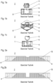
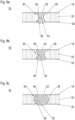
- FIG. 1a, 1b, 1c, 2a and 2b A known installation method is shown in the Figures 1a, 1b, 1c, 2a and 2b .
- a bore hole is prepared in a sandwich structure by a drilling 3 tool.
- the hole 1 is widened by a reaming tool 5 such the core element has a greater inner hole diameter than the cover sheets 6.
- a potting mass 10 such as an epoxy-based compound is filled in.
- the potting mass 10 is pressed in the core element 4 and the destroyed chambers 8 until it is distributed throughout the destroyed chambers 8. As can be seen in Figures 2a and 2b , the distribution and such the amount of potting mass 10 can differ significantly.
- the volume of the potting mass 10 depends randomly on the destroyed core element 4. In consequence, measured weights of the potting mass 10 are often significantly higher than specified, for instance six times higher. Therefore, a controllable potting mass volume (amount) would provide significant weight opportunities.
- the potting mass As the hollow body forms a barrier for the potting mass, the potting mass is kept inside the filling room and cannot be distributed outside the filling room to the destroyed chambers. Thus, the volume of the potting mass can be precisely calculated. As the potting mass is in direct contact with the inner surface areas, the insert is ready for withstanding high loads.
- the term insert is used for any mechanical fasting element such as a screw threat which is hold by the cured potting mass in its desired position inside the hollow body and thus inside the hole, but also for a through hole that is created after the potting mass is cured in the hollow body.
- the hole is a through hole, the opposite inner surface areas forming inner annular undercuts created by widening the hole diameter in the core element. If the hole is a blind hole, on the one side (hole in cover sheet) the inner surface area is an inner annular undercut and on the opposite side (no hole in cover sheet) the inner surface area is a circular area, both also created by widening the hole diameter in the core element.
- the hollow body is compressed before installation and expands in the sandwich structure after installation.
- the hollow body is aligned automatically in the hole and the filling room is automatically opened.
- the hollow body comprises a stretchable hull and a separate flexible stiffener.
- the stiffener is positioned inside the hull.
- the hull is forming a barrier for the potting mass.
- the stiffener shapes the hull.
- a hollow body can be used comprising a stretchable hull having integrated stiffening characteristics. By means of this, the installation of the insert is more simplified.
- the hollow body is created directly in the hole by laying material lines spirally over each other. This can be done by 3D-printing. If necessary, a support structure can be provided in order to support the laid material lines and protect them against collapsing as long as they are not cured sufficiently.
- At least one riser opening is provided in at least one of the inner surface areas. As soon as the filling mass enters the rise opening, the filling process is stopped.
- the at least one riser opening is positioned in a radial outer position of the at least one inner surface area. More preferably, several riser openings are provided.
- a sandwich structure has two cover sheets and a core element such as a honeycomb structure.
- the core element is bonded to inner surfaces of the cover sheets.
- An insert is provided in a hollow body positioned in a hole of the sandwich structure and filled with a potting mass.
- the hollow body defines a filling room for the potting mass and extends between opposite inner surface areas of the cover sheets such that the potting mass is distributed on the inner surface areas.
- the potting mass is kept inside the filling room and cannot be distributed outside the filling room to the destroyed chambers.
- the volume of the potting mass can be precisely calculated in advance and the sandwich structure is weight optimised.
- a compressible and self-expandable hollow body which is adapted to be used in an inventive method or to be installed in an inventive sandwich structure, has a tube-like shape in its self-expanded mode and a circumferentially wall forming a radially potting mass barrier.
- the hollow body opens itself radially and (axially) such that at least end portions of its hull (potting mass barrier) move in direct contact along the inner surface of the cover sheets thus forming the inner surface areas.
- the hollow body comprises a stretchable hull and a separate flexible stiffener.
- the hull defines a potting mass barrier and restricts radially the filling room. By using two separate parts, both parts can be functionally optimised.
- the hull can be an elastic foil, but also an elastic fabric such as a fabric having a mesh size which is small enough to avoid any escape of the uncured potting mass out of the filling room.
- the hollow body comprises a stretchable hull having integrated stiffening characteristics.
- An exemplary hull has a wall thickness of between 0,25mm and 1mm and can be a 3D printed Thermoplastic Urethane Resin (TPU) or a 3D printed Stereolithography (SLA) resin.
- TPU Thermoplastic Urethane Resin
- SLA Stereolithography
- the hollow body can have a constant diameter over its entire length.
- the hollow body has a cylindrical shape.
- hollow body has auxetic shape characteristics. This means, the overall structure become thicker perpendicular to the applied force. The hollow body expands when it is stretched and contracts when it is compressed.
- the hollow body can have a radially reduced centre portion compart to its end portions.
- the hollow body has a diabolo shape.
- Figure 3a and 3b inserts are shown which are installed in a hole of a sandwich structure according to the inventive method.
- the sandwich structure can be used for monument walls, floor panel and cabin linings, for instance.
- the sandwich structure 16 has an upper cover sheet 18 and a lower cover sheet 20. Between the cover sheets 18, 20 a core element 22 is positioned. The core element 22 is bonded to inner surfaces 24, 26 of the cover sheets 18, 20.
- An exemplary core element 22 has a honeycomb structure with a plurality of chambers 28 (not shown).
- the inserts 12 are provided.
- the inserts 12 are located in a hole 14 of the sandwich structure 16.
- the insert 12 is a through hole extending through the upper cover sheet 18, the core element 22 and the lower cover sheet 20.
- the insert 12 is a screw thread, whereas the hole 14 is a blind hole that only extends through the upper cover sheet 18 into the core element 22.
- the insert 12 is radially surrounded by a hollow body.
- a space between the insert 12 and the hollow body 30 is filled with a potting mass 32 such as an epoxy resin.
- the hollow body 30 has a tube-like shape and defines a filling room 33 for the potting mass 32 preventing that the potting mass 32 escapes radially into destroyed chambers 28 of the core element. It is compressible and self-expandable, such that in its installed position, its opposite end portions 34, 36 are in direct contact with the inner surfaces 24, 26 of the cover sheets 18, 20. Due to the self-expandable characteristics, after their positioning in the hole 14, its end portions 38, 40 move automatically radially outwards "beyond" the inner surfaces 18, 20. By means of this, opposite inner surface areas 38, 40 are created which are concentrically to the hole 14 and which form an undercut for the potting mass 10.
- both inner surface areas 38, 40 have an annular shape.
- one inner surface area 24 has an annular shape (upper cover sheet 18) and the opposite inner surface area 26 has a circular shape (lower cover sheet 20).
- each embodiment has a potting mass 32 proof hull 42 defining a filling room 33 for the potting mass 32.
- the hull 42 acts as a barrier and prevents that potting mass 32 which is filled in the filling room cannot escape radially to the outside.
- the hull 42 is flexible (stretchable), whereas in the embodiment shown in Figure 4c the hull 42 is stiff.
- Exemplary hulls 42 are made of a foil bag material or a fabric. If the hull 42 is made as a fabric, fabric meshes are adjusted to the viscosity of the potting mass 32 in order to avoid any penetration.
- the hollow body 30 further has a stiffener 44.
- the stiffener 44 is compressible and self-expandable such that if a compression is terminated, the stiffener 44 takes its initial shape again.
- the stiffener can be made via 3D-printing.
- the hull 42 and the stiffener 44 can be separated parts which are assembled together before installation in the sandwich structure. Thereby, the stiffener 44 is put in the interior of the hull 42 and the hull 42 is kept opened.
- the stiffener 44 (indicated by the dotted line) can also be fully integrated in the hull 42.
- the hull 42 has internal compressible and expandable characteristics.
- This single piece hollow body 30 can be made via additive manufacturing, for instance 3D-printing.
- the hollow body 30 comprises only a stiff hull 42.
- a stiffener 44 is not provided.
- This hull 42 is integrated in the sandwich structure 16 via 3D-printing. For instance, a plurality of material lines 46 is laid up spirally one over the other. This kind of installation method will be explained in more detailed regarding Figure 7a, 7b and 7c .
- FIGS 5a to 5f a preferred method according to the invention is shown to install an insert 12 in a sandwich structure 16.
- the insert 12 is a through hole.
- a hole 14 is provided in the sandwich structure 16 that extends through the entire sandwich structure 16 and thus through both cover sheets 18, 20.
- the hole 14 is radially widened such that an inner diameter d core of the hole in the core structure 22 is larger than (initial) inner diameters d sheet of the hole 14 in the cover sheets 18, 20.
- the hollow body 30 is inserted in the hole 14.
- the hollow body 30 has in its expanded state (normal state) an outer diameter which is larger than the initial hole diameter d sheet and preferably also larger than the widened hole diameter d core , the hollow body 30 is compressed radially first and then inserted into the hole 14.
- the hollow body 30 expands and moves with its end portions 34, 36 along the inner surfaces 24, 26 such that annular inner surface areas 38, 40 are provided forming the undercut for the potting mass 32.
- the filling room 33 for the potting mass 32 is defined so that chambers 28 of the sandwich structure 16 are "sealed” against the potting mass 32.
- the potting mass 32 is filled in until the filling room 33 is entirely filled with the potting mass 32. Thereby, due to the undercuts, the potting mass 32 connects the upper cover layer 18 and the lower cover sheet 20 and is bonded to them.
- the insert 12 in the form of the through hole is provided in the potting mass 32 inside the hollow body 30.
- the through hole 12 is made in the potting mass 32 by a drilling tool 48.
- FIGS 6a, 6b and 6c another preferred method according to the invention is shown to install an insert 12 in a sandwich structure 16.
- the insert is a screw thread 12.
- a blind hole 14 is provided in the sandwich structure 16 that extends through the upper cover sheet 18 and through the core element 22, but not through the lower cover sheet 20. Further on, the insert 12 is provided in the hollow body 30 before filling in the potting mass 32 and not afterwards.
- the hole 14 is provided in the sandwich structure 16.
- the hole 14 is radially widened such that an inner diameter d core of the hole 14 in the core element 22 is larger than (initial) inner diameters d sheet of the hole 14 in the upper cover sheet 18.
- hollow body 30 is inserted in the hole 14.
- the screw thread 12 is positioned in the hollow body 30.
- the screw thread 12 is positioned in the hollow body 30 after the positioning of the hollow body 30 in the hole 14.
- an upper end portion 34 of the hollow body 30 defines an annular inner surface area 38 forming the undercut for a potting mass 32.
- the hollow body 30 With its lower end portion 36, the hollow body 30 is in contact with the inner surface 26 of the lower cover sheet 20 and forms an inner surface area 40 having a circular shape.
- the potting mass 32 is filled in until the filling room 33 is entirely filled with the potting mass 32. Thereby, due to the upper undercut (inner surface area 38) and the lower circular inner surface area (inner surface area 40), the potting mass 32 connects the upper cover layer 18 and the lower cover sheet 20 and is bonded to them.
- the hollow body is built up in a hole 14 of the sandwich structure 16 directly.
- the hollow body 30 has only a potting mass proof hull 42, which is created by 3D-printing material lines 46 one over the other.
- a print tool 50 is inserted and spirally lays up the material lines 46 until the hull 42 extends from an inner surface 26 of the lower cover sheet 22 to an inner surface 24 of the upper cover sheet 18 and defines a filling room 33 for a potting mass 32.
- the hull 42 does not need any flexible characteristics. Consequently, a stiffener 44 is not necessary.
- the upper material lines 46 are thus positioned that they define annular inner surface areas 38, 40 forming an undercut for the potting mass 32.
- the hollow body 30 is prepared for filling in the potting mass 32.
- FIGs 8a, 8b and 8c installed hollow bodies 30 are shown which are filled with a potting mass 32.
- the hollow bodies 30 are positioned in a hole 14 extending through an upper cover sheet 18, a core element 22 and a lower cover sheet 20 and filled with a cured potting mass 32.
- All hollow bodies 30 are manufactured in the same way and are of the same type. They are 3D-printed and having a hull 42 with internal compressible and expandable characteristics. A separate stiffener 44 is not provided.
- the tubular hollow body 30 shown in Figure 8a has radially reduced centre portion 52 compart to its end portions 34, 36.
- the hollow body 30 has a diabolo shape.
- its centre portion 52 is thinner than its end portions 34, 36.
- the tubular hollow body shown in Figure 8b has an auxetic shape.
- the hollow body 30 expands when stretched and contracts when compressed.
- its centre portion 52 is thinner than its end portions 34, 36, but in this embodiment compared with the diabolo shape shown in Figure 8a , the centre portion 52 of the auxetic shape is bigger.
- the tubular hollow body shown in Figure 8c has in its normal state a constant diameter over its entire length.
- the hollow body 30 has a cylindrical shape.
- its centre portion 52 is bigger than its end portions 34, 36.
- riser opening 54a, 54b in the upper cover sheet 18 and/or lower cover sheet 20 can be provided.
- the riser openings 54a, 54b are poisoned radially outwards inner surface areas 38, 40.
- the riser openings 54a, 54b have such a diameter that the potting mass 32 moving along the inner surface areas 38, 40 (entering the undercuts) can escape (reference sign 56a, 56b). The penetration shows the user visually that the potting mass 32 is distributed in a right manner.
- a method for placing an insert in a sandwich structure such as a honeycomb structure, wherein a potting mass filling room is provided in a sandwich hole having a room wall preventing penetration of the honeycomb chambers, a sandwich structure and a hollow body forming the filling room.
Landscapes
- Engineering & Computer Science (AREA)
- General Engineering & Computer Science (AREA)
- Mechanical Engineering (AREA)
- Laminated Bodies (AREA)
Priority Applications (1)
| Application Number | Priority Date | Filing Date | Title |
|---|---|---|---|
| EP23184146.1A EP4488529A1 (fr) | 2023-07-07 | 2023-07-07 | Installation d'insert dans une structure sandwich, structure sandwich et corps creux |
Applications Claiming Priority (1)
| Application Number | Priority Date | Filing Date | Title |
|---|---|---|---|
| EP23184146.1A EP4488529A1 (fr) | 2023-07-07 | 2023-07-07 | Installation d'insert dans une structure sandwich, structure sandwich et corps creux |
Publications (1)
| Publication Number | Publication Date |
|---|---|
| EP4488529A1 true EP4488529A1 (fr) | 2025-01-08 |
Family
ID=87377839
Family Applications (1)
| Application Number | Title | Priority Date | Filing Date |
|---|---|---|---|
| EP23184146.1A Pending EP4488529A1 (fr) | 2023-07-07 | 2023-07-07 | Installation d'insert dans une structure sandwich, structure sandwich et corps creux |
Country Status (1)
| Country | Link |
|---|---|
| EP (1) | EP4488529A1 (fr) |
Citations (8)
| Publication number | Priority date | Publication date | Assignee | Title |
|---|---|---|---|---|
| DE2707492A1 (de) * | 1977-02-21 | 1978-08-24 | Bostik Gmbh | Verfahren zum verbinden von zwei aneinander angrenzenden oberflaechen und dafuer geeignetes rohrverbindungselement |
| US4428705A (en) * | 1980-11-11 | 1984-01-31 | Messerschmitt-Boelkow-Blohm Gesellschaft Mit Beschraenkter Haftung | Spreading dowel for securing an insert in a panel with the aid of the dowel |
| FR2577629A1 (fr) * | 1985-02-14 | 1986-08-22 | Cougnaud Fils Sa Ets | Cheville pour la fixation d'objets a l'aide d'une vis contre une cloison creuse |
| CN101484035A (zh) * | 2006-06-05 | 2009-07-15 | 耐克国际有限公司 | 具有侧向和剪切力稳定性的冲击减弱构件及包括其的产品 |
| US20110187035A1 (en) * | 2009-11-20 | 2011-08-04 | Cagle Jakob B | Compression spring assembly and method |
| WO2014143195A1 (fr) * | 2013-03-15 | 2014-09-18 | Rolls-Royce Canada, Ltd. | Goupille de verrouillage auxétique |
| WO2016102792A1 (fr) * | 2014-12-24 | 2016-06-30 | Airbus Defence And Space Sas | Dispositif de fixation amortissant entre deux éléments à assembler, procédé de fabrication d'un tel dispositif, ensemble de deux éléments assemblés à l'aide d'un tel dispositif, et procédé d'assemblage |
| EP3372390A1 (fr) * | 2017-03-09 | 2018-09-12 | AIRBUS HELICOPTERS DEUTSCHLAND GmbH | Procédé de réparation d'un composant en sandwich ayant un élément de noyau disposé entre une première et une seconde plaque de recouvrement |
-
2023
- 2023-07-07 EP EP23184146.1A patent/EP4488529A1/fr active Pending
Patent Citations (8)
| Publication number | Priority date | Publication date | Assignee | Title |
|---|---|---|---|---|
| DE2707492A1 (de) * | 1977-02-21 | 1978-08-24 | Bostik Gmbh | Verfahren zum verbinden von zwei aneinander angrenzenden oberflaechen und dafuer geeignetes rohrverbindungselement |
| US4428705A (en) * | 1980-11-11 | 1984-01-31 | Messerschmitt-Boelkow-Blohm Gesellschaft Mit Beschraenkter Haftung | Spreading dowel for securing an insert in a panel with the aid of the dowel |
| FR2577629A1 (fr) * | 1985-02-14 | 1986-08-22 | Cougnaud Fils Sa Ets | Cheville pour la fixation d'objets a l'aide d'une vis contre une cloison creuse |
| CN101484035A (zh) * | 2006-06-05 | 2009-07-15 | 耐克国际有限公司 | 具有侧向和剪切力稳定性的冲击减弱构件及包括其的产品 |
| US20110187035A1 (en) * | 2009-11-20 | 2011-08-04 | Cagle Jakob B | Compression spring assembly and method |
| WO2014143195A1 (fr) * | 2013-03-15 | 2014-09-18 | Rolls-Royce Canada, Ltd. | Goupille de verrouillage auxétique |
| WO2016102792A1 (fr) * | 2014-12-24 | 2016-06-30 | Airbus Defence And Space Sas | Dispositif de fixation amortissant entre deux éléments à assembler, procédé de fabrication d'un tel dispositif, ensemble de deux éléments assemblés à l'aide d'un tel dispositif, et procédé d'assemblage |
| EP3372390A1 (fr) * | 2017-03-09 | 2018-09-12 | AIRBUS HELICOPTERS DEUTSCHLAND GmbH | Procédé de réparation d'un composant en sandwich ayant un élément de noyau disposé entre une première et une seconde plaque de recouvrement |
Similar Documents
| Publication | Publication Date | Title |
|---|---|---|
| JP2003533648A (ja) | 合わせガラス用の固定部材及びプレート状の多層体中に固定された固定部材を有する装置 | |
| CN102143839B (zh) | 具有整合的增强结构的夹心板及其制造方法 | |
| JP5655625B2 (ja) | インサートナットのパネルへの取り付け構造 | |
| US9540806B2 (en) | Facing element for a building | |
| US8387340B2 (en) | Anchor for a lightweight construction panel and its installation in the panel | |
| WO1994024471A1 (fr) | Element coupe-feu | |
| JP5611988B2 (ja) | 薄壁包囲要素を固定するための固定治具 | |
| MXPA01008558A (es) | Aislamiento zonal selectivo, dentro de un revestimiento ranurado. | |
| EP4488529A1 (fr) | Installation d'insert dans une structure sandwich, structure sandwich et corps creux | |
| JP2011162141A (ja) | 衝撃吸収構造体及び衝撃吸収構造体の製造方法、並びに、移動体 | |
| EP2930011A1 (fr) | Procédé de réparation d'un composant en sandwich ayant un noyau en nid d'abeilles avec une hauteur de noyau associée | |
| CN112709927A (zh) | 高压罐、具备高压罐的车辆、以及高压罐的制造方法 | |
| US4685589A (en) | Composite pressure vessel including a fluid port directly through the composite side wall structure | |
| EP2744705A1 (fr) | Panneau intérieur d'aéronef à haute résistance comportant un insert incorporé | |
| EP1369599A1 (fr) | Une attache aveugle améliorée | |
| US9682529B2 (en) | Sandwich panels and method for producing sandwich panels | |
| EP2886445A1 (fr) | Fuselage d'avion sous pression, comprenant une cloison de pressurisation mobile fixée au fuselage | |
| US9386825B2 (en) | Locally reinforced aircraft structural component | |
| CN113104192B (zh) | 抗剪带连接件系统及用于安装抗剪带连接件系统的方法 | |
| EP1986299A1 (fr) | Boîtier pour câblages électriques dans les sols et les murs | |
| EP2944455B1 (fr) | Procédé de réparation d'un composant en sandwich ayant un noyau en nid d'abeilles qui est disposée entre une première et une seconde plaque de recouvrement | |
| CN106167103A (zh) | 用于增强拔出强度的模制嵌件 | |
| WO2022125615A1 (fr) | Manchon repérable de protection et son procédé de construction | |
| EP4269818B1 (fr) | Inserts moulés comprenant une structure en treillis et procédé de fixation d'objets sur des panneaux sandwich à l'aide de ces derniers | |
| JP6370622B2 (ja) | 折り畳み展開可能な補強部材及びその製造方法 |
Legal Events
| Date | Code | Title | Description |
|---|---|---|---|
| PUAI | Public reference made under article 153(3) epc to a published international application that has entered the european phase |
Free format text: ORIGINAL CODE: 0009012 |
|
| STAA | Information on the status of an ep patent application or granted ep patent |
Free format text: STATUS: THE APPLICATION HAS BEEN PUBLISHED |
|
| AK | Designated contracting states |
Kind code of ref document: A1 Designated state(s): AL AT BE BG CH CY CZ DE DK EE ES FI FR GB GR HR HU IE IS IT LI LT LU LV MC ME MK MT NL NO PL PT RO RS SE SI SK SM TR |
|
| STAA | Information on the status of an ep patent application or granted ep patent |
Free format text: STATUS: REQUEST FOR EXAMINATION WAS MADE |
|
| 17P | Request for examination filed |
Effective date: 20250708 |