EP4488531A1 - Dispositif de fixation et ensemble de fixation pour fixer des pièces - Google Patents
Dispositif de fixation et ensemble de fixation pour fixer des pièces Download PDFInfo
- Publication number
- EP4488531A1 EP4488531A1 EP22929563.9A EP22929563A EP4488531A1 EP 4488531 A1 EP4488531 A1 EP 4488531A1 EP 22929563 A EP22929563 A EP 22929563A EP 4488531 A1 EP4488531 A1 EP 4488531A1
- Authority
- EP
- European Patent Office
- Prior art keywords
- plug
- fastener
- elastic
- head
- clamping
- Prior art date
- Legal status (The legal status is an assumption and is not a legal conclusion. Google has not performed a legal analysis and makes no representation as to the accuracy of the status listed.)
- Pending
Links
Images


Classifications
-
- F—MECHANICAL ENGINEERING; LIGHTING; HEATING; WEAPONS; BLASTING
- F16—ENGINEERING ELEMENTS AND UNITS; GENERAL MEASURES FOR PRODUCING AND MAINTAINING EFFECTIVE FUNCTIONING OF MACHINES OR INSTALLATIONS; THERMAL INSULATION IN GENERAL
- F16B—DEVICES FOR FASTENING OR SECURING CONSTRUCTIONAL ELEMENTS OR MACHINE PARTS TOGETHER, e.g. NAILS, BOLTS, CIRCLIPS, CLAMPS, CLIPS OR WEDGES; JOINTS OR JOINTING
- F16B5/00—Joining sheets or plates, e.g. panels, to one another or to strips or bars parallel to them
- F16B5/06—Joining sheets or plates, e.g. panels, to one another or to strips or bars parallel to them by means of clamps or clips
- F16B5/0607—Joining sheets or plates, e.g. panels, to one another or to strips or bars parallel to them by means of clamps or clips joining sheets or plates to each other
- F16B5/0621—Joining sheets or plates, e.g. panels, to one another or to strips or bars parallel to them by means of clamps or clips joining sheets or plates to each other in parallel relationship
- F16B5/065—Joining sheets or plates, e.g. panels, to one another or to strips or bars parallel to them by means of clamps or clips joining sheets or plates to each other in parallel relationship the plates being one on top of the other and distanced from each other, e.g. by using protrusions to keep contact and distance
-
- F—MECHANICAL ENGINEERING; LIGHTING; HEATING; WEAPONS; BLASTING
- F16—ENGINEERING ELEMENTS AND UNITS; GENERAL MEASURES FOR PRODUCING AND MAINTAINING EFFECTIVE FUNCTIONING OF MACHINES OR INSTALLATIONS; THERMAL INSULATION IN GENERAL
- F16B—DEVICES FOR FASTENING OR SECURING CONSTRUCTIONAL ELEMENTS OR MACHINE PARTS TOGETHER, e.g. NAILS, BOLTS, CIRCLIPS, CLAMPS, CLIPS OR WEDGES; JOINTS OR JOINTING
- F16B21/00—Means for preventing relative axial movement of a pin, spigot, shaft or the like and a member surrounding it; Stud-and-socket releasable fastenings
- F16B21/06—Releasable fastening devices with snap-action
- F16B21/07—Releasable fastening devices with snap-action in which the socket has a resilient part
- F16B21/073—Releasable fastening devices with snap-action in which the socket has a resilient part the socket having a resilient part on its inside
-
- F—MECHANICAL ENGINEERING; LIGHTING; HEATING; WEAPONS; BLASTING
- F16—ENGINEERING ELEMENTS AND UNITS; GENERAL MEASURES FOR PRODUCING AND MAINTAINING EFFECTIVE FUNCTIONING OF MACHINES OR INSTALLATIONS; THERMAL INSULATION IN GENERAL
- F16B—DEVICES FOR FASTENING OR SECURING CONSTRUCTIONAL ELEMENTS OR MACHINE PARTS TOGETHER, e.g. NAILS, BOLTS, CIRCLIPS, CLAMPS, CLIPS OR WEDGES; JOINTS OR JOINTING
- F16B19/00—Bolts without screw-thread; Pins, including deformable elements; Rivets
- F16B19/02—Bolts or sleeves for positioning of machine parts, e.g. notched taper pins, fitting pins, sleeves, eccentric positioning rings
-
- F—MECHANICAL ENGINEERING; LIGHTING; HEATING; WEAPONS; BLASTING
- F16—ENGINEERING ELEMENTS AND UNITS; GENERAL MEASURES FOR PRODUCING AND MAINTAINING EFFECTIVE FUNCTIONING OF MACHINES OR INSTALLATIONS; THERMAL INSULATION IN GENERAL
- F16B—DEVICES FOR FASTENING OR SECURING CONSTRUCTIONAL ELEMENTS OR MACHINE PARTS TOGETHER, e.g. NAILS, BOLTS, CIRCLIPS, CLAMPS, CLIPS OR WEDGES; JOINTS OR JOINTING
- F16B21/00—Means for preventing relative axial movement of a pin, spigot, shaft or the like and a member surrounding it; Stud-and-socket releasable fastenings
- F16B21/06—Releasable fastening devices with snap-action
- F16B21/07—Releasable fastening devices with snap-action in which the socket has a resilient part
- F16B21/076—Releasable fastening devices with snap-action in which the socket has a resilient part the socket having a resilient part on its outside
-
- F—MECHANICAL ENGINEERING; LIGHTING; HEATING; WEAPONS; BLASTING
- F16—ENGINEERING ELEMENTS AND UNITS; GENERAL MEASURES FOR PRODUCING AND MAINTAINING EFFECTIVE FUNCTIONING OF MACHINES OR INSTALLATIONS; THERMAL INSULATION IN GENERAL
- F16B—DEVICES FOR FASTENING OR SECURING CONSTRUCTIONAL ELEMENTS OR MACHINE PARTS TOGETHER, e.g. NAILS, BOLTS, CIRCLIPS, CLAMPS, CLIPS OR WEDGES; JOINTS OR JOINTING
- F16B21/00—Means for preventing relative axial movement of a pin, spigot, shaft or the like and a member surrounding it; Stud-and-socket releasable fastenings
- F16B21/06—Releasable fastening devices with snap-action
- F16B21/08—Releasable fastening devices with snap-action in which the stud, pin, or spigot has a resilient part
- F16B21/086—Releasable fastening devices with snap-action in which the stud, pin, or spigot has a resilient part the shank of the stud, pin or spigot having elevations, ribs, fins or prongs intended for deformation or tilting predominantly in a direction perpendicular to the direction of insertion
-
- F—MECHANICAL ENGINEERING; LIGHTING; HEATING; WEAPONS; BLASTING
- F16—ENGINEERING ELEMENTS AND UNITS; GENERAL MEASURES FOR PRODUCING AND MAINTAINING EFFECTIVE FUNCTIONING OF MACHINES OR INSTALLATIONS; THERMAL INSULATION IN GENERAL
- F16B—DEVICES FOR FASTENING OR SECURING CONSTRUCTIONAL ELEMENTS OR MACHINE PARTS TOGETHER, e.g. NAILS, BOLTS, CIRCLIPS, CLAMPS, CLIPS OR WEDGES; JOINTS OR JOINTING
- F16B5/00—Joining sheets or plates, e.g. panels, to one another or to strips or bars parallel to them
- F16B5/06—Joining sheets or plates, e.g. panels, to one another or to strips or bars parallel to them by means of clamps or clips
- F16B5/0692—Joining sheets or plates, e.g. panels, to one another or to strips or bars parallel to them by means of clamps or clips joining flexible sheets to other sheets or plates or to strips or bars
Definitions
- the present invention relates to a fastener technology for motor vehicles, and more particularly to a fastener and a fastening assembly for fixing components.
- fasteners In automobile manufacturing, various types of fasteners are used to connect or clamp two or more components together, such as fixing air curtains or airbags to a frame. Moreover, different components or positions require different fasteners.
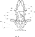
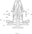
- the fastening assembly for fixing components includes a fastener 10 for fixing components, and a plug 20 inserted into the fastener 10. Understandably, the fastening assembly for fixing components can be used to fix air curtains or airbags on a car sheet metal of automobiles, or to fix other components.
- the air curtains or airbags themselves should be a prior art and will not be further described here.
- the fastener 10 includes a head section 11, a body 12 connected to the head section 11, and two clamping portions 13 respectively disposed at one end of the body 12.
- the fastener 10 can be formed by stamping a single metal plate, thereby reducing the manufacturing process, lowering manufacturing costs, and accelerating manufacturing efficiency.
- the head section 11 has a curled structure that curls inward from both ends, so as for forming the body 12. Therefore, the structure of the head section 11 can be designed according to actual requirements.
- the head section 11 is curled into a plate-like structure.
- the head section 11 is provided with a through-hole 111 thereon.
- the through-hole 111 is configured for inserting the plug 20, therefore its shape can be set according to the cross-sectional shape of the plug 20, such as square or circular.
- a shape of the through-hole 111 is square.
- the body 12 includes a connecting portion 121, two elastic portions 122 spaced apart and extending from the connecting portion 121, two plug holes 123 provided on the connecting portion 121 or the elastic portion 122, and two contact holes 124 connected to the plug holes 123 respectively.
- the connecting part 121 is made by stamping two free ends of the head section 11, and forms a square cylindrical structure. A hollow part of the square cylindrical structure is in line with the through-hole 111 so as to facilitate the insertion of the plug 20.
- the connecting portion 121 may be a circular cylinder.
- the two elastic portions 122 have the same structure.
- the two elastic portions 122 are spaced apart and arranged relative to each other, and free ends of the two elastic portions 122 are closed towards each other so as to make the two elastic portions 122 have elasticity. Moreover, the two elastic portions 122 bend at the same angle to make the two elastic portions 122 have same elastic force.
- At least one avoidance groove 125 is provided on a side of the elastic portion 122. In the present embodiment, two avoidance grooves 125 are respectively provided on two sides of the elastic portion 122. The arrangement direction of the two avoidance grooves 125 is perpendicular to that of the connecting portion 121 and the elastic portion 122. The avoidance groove 125 is configured to cooperate with the clamping portion 13, and it will be explained in detail below.
- the plug hole 123 can be a rectangular hole, and a length direction of the rectangular hole is parallel to that of the connecting portion 121 and the elastic portion 122.
- the plug hole 123 is configured to cooperate with the plug20, and it will be explained in detail together with the plug 20 below.
- the contact hole 124 is connected to the plug hole 123 and is located on a side facing the head section 11. Positions of the plug hole 123 and the contact hole 124 can be arranged according to actual needs, such as the need to cooperate with the plug 20.
- the plug hole 123 and the contact hole 124 can be all provided on the elastic portion 122, or all provided on the connection portion 121, or partially provided on the elastic portion 122 and partially provided on the connection portion 121.
- a portion of the plug hole 121 is provided on the elastic portion 122, and another portion thereof is provided on the connecting portion 121.
- the contact hole 124 is provided on the connecting portion 121.
- the two plug holes 123, the two connection portions 121, and the elastic portions 122 are respectively arranged on the two connecting portions 121.
- the clamping portions 13 have two, and the two clamping portions 13 have the same structure. Each of the clamping portion 13 extends from a free end of the elastic portion 122. An extension direction of the clamping portion 13 is opposite to that of the free end of the elastic portion 122 so that a main body parts of the clamping portion 13 and the elastic portion 122 overlap with each other. Due to the free ends of the elastic portions 122 being closed towards each other, the two clamping portions 13 are pressed against each other at a connection point with the elastic portion 122 so as to avoid deformation when the connection point of the elastic portion 122 and the clamping portions 13 are inserted into the hole of the car sheet metal and improving deformation strength thereof.
- Each of the clamping portions 13 includes at least one clamping head 131 inserted into the avoidance groove 125, and an abutment head 132 provided at a free end of the clamping portions 13.
- An arrangement position of the clamping head 131 should be able to be inserted into the avoidance groove 125, so it will not be described in detail.
- One side of the clamping head 131 facing the head section 11 is configured to abut against the air curtain or car sheet metal. In order to increase pressing area and avoid deformation or impale the air curtain or airbag, the clamping head 131 is bent towards a side of the head section 11, that is to say, towards the body 12.
- the clamping head 131 has a wedge-shaped structure along the insertion direction of the fastener 10. Therefore, in order to accommodate the clamping portion 131 which is bent at one end, the avoidance groove 125 has a trapezoidal cross-section.
- the abutment head 132 is configured to press against the plug 20 so as to fix the plug 20 in a certain position. Therefore, it will be explained in detail below with the plug 20. In order to achieve effective abutment, the abutment head 132 extends away from the elastic portion 122.
- the plug 20 is configured to fix the relative position between the fastener 10 and the car sheet metal and the air curtain after the fastener 10 is inserted into the car sheet metal and the air curtain. That is to say, the plug 20 is configured to prevent the fastener 10 from falling out of the car sheet metal or the air curtain. Moreover, the plug 20 is configured to ensure that the clamping portion 13 does not deform or even close, which may cause the clamping head 131 to fall out of the hole in the car sheet metal or the air curtain.
- the plug 20 can be directly injection molded from materials such as plastic.
- the plug 20 includes a pressing portion 21, two positioning portions 22 spaced apart and connected to the pressing portion 21, and a limiting portion 23 positioned between the pressing portion 21 and the positioning portion 22.
- the pressing portion 21 can be a plate-shaped structure so as to be convenient for users to press by hands or tools.
- the two positioning portions 22 extend from the pressing portion 21 and are two independent components symmetrically arranged. When the two positioning portions 22 are in a free state, they are in a separated state.
- the two positioning portions 22 have the same structure, and only one is described in detail as an example to illustrate a structure of the two positioning portions 22.
- the positioning portion 22 includes an elastic member 221 connected to the pressing portion 21, a positioning head 222 provided at a free end of the elastic member 221, and a plug-in abutting portion 223 provided on the elastic member 221.
- the elastic member 221 is a rod and extends from the pressing portion 21.
- the elastic member 221 utilizes its inherent ductility to achieve the purpose of making it have elastic, that is to say, the two positioning portions 22 can be closed or separated.
- the positioning head 222 includes a connector 224 for inserting into the plug hole 123, a stepped portion 225 provided on the connector 224, and a locking slot 226 provided on a free end of the connector 224.
- the stepped portion 225 is opened on a side wall of the connector 224, and its structure and shape are determined by its function.
- the connector 224 will detach from the plug hole 123, and at the same time, the two positioning portions 22 will be closed to make the two plug 224 abut against the clamping portion 13 so as to prevent the two clamping portions 13 from flipping and improving the strength of the fastener 10.
- the stepped portion 225 is provided. Therefore, a position and shape of the stepped portion 225 should be such that the two connectors 224 can be pressed against each other when the two positioning portions 22 are closed.
- the plug-in abutting portion 223 is configured to fix a relative position between the plug 20 and the fastener 10 when the plug 20 is fully inserted into the fastener 10.
- the plug-in abutting portion 223 is arranged between the connector 224 and the pressing portion 21 and includes an elastic connecting portion 227 connected to the elastic member 221, and a plug-in head 228 arranged on the elastic connecting portion 227.
- An extension direction of the elastic connector portion 227 is inclined towards the head section 11 so as to avoid preventing the plug 20 from being inserted into the fastener 10.
- the plug-in head 228 is arranged on the elastic connecting portion 227 and extends towards the body 12 so as to form a branching structure with the elastic connecting portion 227.
- a position of the plug-in head 228 should be such that the plug-in head 228 can be inserted into the contact hole 124 when the plug 20 is fully inserted into the fastener 10. Therefore, a structure and shape of the plug-in head 228 should be the same as that of the contact hole 124.
- the limiting portion 23 is configured to restrict a position of the plug 20 inserted into the fastener 10 and is abutted against the head section 11.
- the plug-in head 228 is inserted into the contact hole 124 and abut against the contact hole 124 so as to fix the plug 20 and the fastener 10.
- the limiting portion 23 and the plug-in head 228 has a certain elastic recovery force so as to tightly fix the plug 20 in the fastener 10. Therefore, a structure and installation position of the limiting portion 23 should be able to form the above-mentioned rebound force with the plug-in head 228.
- the fastener 10 and the plug 20 is firstly assembled in the pre-installed state, that is to say, the fastening assembly has not yet been inserted into the hole of the car sheet metal and the air curtain in the pre-installed state for transportation.
- the plug 20 is inserted into the through-hole 111 of the head section 11 of the fastener 10, and the connector 224 on the positioning member 222 of the positioning portion 22 is inserted and clamped in the plug hole 123.
- the plug 20 is fixed to the fastener 10 without falling off, which make it easy to use.
- the fastening assembly When in use, the fastening assembly is inserted into the hole of the car sheet metal and the airbag from the free end of the elastic portion 122, and during the insertion process, the car sheet metal will compress the clamping head 131 of the clamping portion 13 so as to make it shrink back into a space formed by the two elastic portions 122, until the car sheet metal and the airbag are wrapped on the plug hole 121 of the body 12. At this time, the clamping head 131 will return to its original position under the restoring force of the elastic portion 122 so as for clamping the car sheet metal and airbag between the clamping head 131 and the head section 11.
- the connector 224 is pressed out of the plug hole 123, and the abutment head 132 is disengaged from the locking slot 226. Therefore, the entire plug 20 can be inserted into the fastener 10, thereby completing the fixation of the car sheet metal and the airbag. At this time, the plug-in abutting portion 223 is inserted and pressed into the contact hole 124. As a result, a relative position between the plug 20 and the fastener 10 can be fixed.
- the fastener 10 provided by the present invention for fixing components can be formed by integral stamping of metal materials through structural design, thereby reducing manufacturing and material costs and improving competitiveness.
- the fastener 10 includes the body 12 and the two clamping portions 13, and the clamping portions 13 extend from the free end of the elastic portion 122 of the body 12, and the extension direction of the clamping portions 13 are opposite to that of the free end of the elastic portion 122.
- the free ends of the two elastic portions 122 extend towards each other so that the connecting parts of the two clamping portions 13 and the two elastic portions 122 are pressed against each other, which can provide certain elasticity for the clamping portions 13 so as to contract or expand easily.
- the clamping head 131 is inserted into the avoidance groove 125 so as to avoid interference with the components when the fastener 10 is inserted into the car sheet metal and airbag.
- the clamping head 131 can clamp two components with other structures, it can fix these components and complete the fixation of these components.
- the fastening assembly includes the plug 20, and the plug 20 has the two positioning portions 22, and each of the two positioning portions 22 has the connector 224, the stepped portion 225, and the locking slot 226.
- the fastening assembly When the fastening assembly is not inserted into the components, the locking slot 226 on the free end of the connector 224 is abutted against the abutment head 132 of the free end of the clamping portion 13, thereby preventing it insert into the components. At this time, it is in the pre-installed state, which is convenient for transportation.
- the components can make the connector 224 to retract, and the two positioning portion 22 abut against each other, and the two stepped portion 225 are overlapped with each other.
- the clamping head 131 disengages from the contact with the avoidance groove 125 so as to allow the entire plug 20 to be inserted into the fastener 10. As a result, the components are fixed.
- the plug-in abutting portion 223 is inserted and abutted against the contact hole 124 of the elastic portion 122, thereby fixing the relative position between the plug 20 and the fastener 10. Moreover, after the plug 20 is fully inserted into the fastener 10, the outer walls of the two connectors 224 are abutted against the clamping portion 13, thereby further preventing deformation. As described above, it can further ensure the clamping and fixing effect of the fastening assembly.
Landscapes
- Engineering & Computer Science (AREA)
- General Engineering & Computer Science (AREA)
- Mechanical Engineering (AREA)
- Insertion Pins And Rivets (AREA)
- Connection Of Plates (AREA)
Applications Claiming Priority (2)
| Application Number | Priority Date | Filing Date | Title |
|---|---|---|---|
| CN202210197364.8A CN114607690B (zh) | 2022-03-01 | 2022-03-01 | 一种用于固定零部件的紧固装置及紧固组件 |
| PCT/CN2022/123962 WO2023165133A1 (fr) | 2022-03-01 | 2022-10-09 | Dispositif de fixation et ensemble de fixation pour fixer des pièces |
Publications (2)
| Publication Number | Publication Date |
|---|---|
| EP4488531A1 true EP4488531A1 (fr) | 2025-01-08 |
| EP4488531A4 EP4488531A4 (fr) | 2025-05-07 |
Family
ID=81861354
Family Applications (1)
| Application Number | Title | Priority Date | Filing Date |
|---|---|---|---|
| EP22929563.9A Pending EP4488531A4 (fr) | 2022-03-01 | 2022-10-09 | Dispositif de fixation et ensemble de fixation pour fixer des pièces |
Country Status (4)
| Country | Link |
|---|---|
| US (1) | US20250188973A1 (fr) |
| EP (1) | EP4488531A4 (fr) |
| CN (1) | CN114607690B (fr) |
| WO (1) | WO2023165133A1 (fr) |
Families Citing this family (3)
| Publication number | Priority date | Publication date | Assignee | Title |
|---|---|---|---|---|
| CN114607690B (zh) * | 2022-03-01 | 2023-06-23 | 嘉兴汉工汽车紧固件有限公司 | 一种用于固定零部件的紧固装置及紧固组件 |
| EP4488530A1 (fr) | 2023-07-04 | 2025-01-08 | Illinois Tool Works Inc. | Ensemble pince de fixation |
| GB202313813D0 (en) * | 2023-09-11 | 2023-10-25 | Illinois Tool Works | Fastening clip |
Family Cites Families (17)
| Publication number | Priority date | Publication date | Assignee | Title |
|---|---|---|---|---|
| SE0700346L (sv) * | 2007-02-12 | 2008-08-13 | Itw Sverige Ab | Fästdon för krockkuddegardin |
| EP2456989B1 (fr) * | 2009-07-24 | 2016-07-06 | Pem Management, Inc. | Dispositif de fixation de panneau à déverrouillage rapide |
| KR20120094653A (ko) * | 2011-02-17 | 2012-08-27 | 주식회사 니프코코리아 | 플라스틱 클립 |
| FR3020098B1 (fr) * | 2014-04-22 | 2017-05-05 | A Raymond Et Cie | Dispositif de fixation par cramponnage |
| CN206054479U (zh) * | 2016-09-27 | 2017-03-29 | 黄山市必利精密塑业科技有限公司 | 一种汽车内饰连接卡扣 |
| CN107939798B (zh) * | 2016-10-12 | 2021-03-09 | 福特环球技术公司 | 用于车辆内饰的固定组件 |
| DE102016124797A1 (de) * | 2016-12-19 | 2018-06-21 | Illinois Tool Works Inc. | Vorrichtung zur Befestigung an einem Befestigungsvorsprung eines Trägerbauteils |
| FR3084118B1 (fr) * | 2018-07-19 | 2020-11-27 | A Raymond Et Cie | Dispositif de fixation de deux elements plans |
| FR3095248B1 (fr) * | 2019-04-16 | 2022-09-16 | A Raymond Et Cie | Dispositif de fixation de deux elements permettant son pre-assemblage |
| EP3754207B1 (fr) * | 2019-06-17 | 2022-08-03 | Illinois Tool Works Inc. | Clip de fixation |
| US10941796B2 (en) * | 2019-07-11 | 2021-03-09 | Newfrey Llc | Two-piece fastener assembly |
| CN110410390A (zh) * | 2019-08-30 | 2019-11-05 | 江铃控股有限公司 | 一种卡接固定件 |
| EP3839273B1 (fr) * | 2019-12-16 | 2024-09-18 | Newfrey LLC | Clip de fixation, système de fixation et procédé de montage de composant |
| CN212360452U (zh) * | 2020-05-21 | 2021-01-15 | 广州众标汽车科技有限公司 | 一种汽车零部件紧固组件 |
| CN212796780U (zh) * | 2020-07-30 | 2021-03-26 | 嘉兴汉工汽车紧固件有限公司 | 一种汽车气帘卡扣 |
| CN215293114U (zh) * | 2021-04-26 | 2021-12-24 | 河南德力新能源汽车有限公司 | 一种新型汽车内饰零部件连接用卡子 |
| CN114607690B (zh) * | 2022-03-01 | 2023-06-23 | 嘉兴汉工汽车紧固件有限公司 | 一种用于固定零部件的紧固装置及紧固组件 |
-
2022
- 2022-03-01 CN CN202210197364.8A patent/CN114607690B/zh active Active
- 2022-10-09 EP EP22929563.9A patent/EP4488531A4/fr active Pending
- 2022-10-09 WO PCT/CN2022/123962 patent/WO2023165133A1/fr not_active Ceased
- 2022-10-09 US US18/843,067 patent/US20250188973A1/en active Pending
Also Published As
| Publication number | Publication date |
|---|---|
| CN114607690B (zh) | 2023-06-23 |
| EP4488531A4 (fr) | 2025-05-07 |
| US20250188973A1 (en) | 2025-06-12 |
| WO2023165133A1 (fr) | 2023-09-07 |
| CN114607690A (zh) | 2022-06-10 |
Similar Documents
| Publication | Publication Date | Title |
|---|---|---|
| EP4488531A1 (fr) | Dispositif de fixation et ensemble de fixation pour fixer des pièces | |
| US5288530A (en) | Trim for installation to automobiles | |
| US20140093311A1 (en) | Mounting structure for parts | |
| CN114930037B (zh) | 金属保持夹 | |
| JP2008224003A (ja) | クランプ構造及び車両用ボディー構造 | |
| US12119603B2 (en) | Two-part grounding clamp for cables | |
| JPH1064611A (ja) | バッテリターミナル | |
| CN214474099U (zh) | 一种光纤连接器 | |
| CN217558702U (zh) | 一种车辆内饰卡扣 | |
| CN213017093U (zh) | 卡扣及车门三角板安装结构 | |
| CN220139131U (zh) | 卡扣结构以及车辆 | |
| CN220947852U (zh) | 一种汽车及车内饰顶棚卡扣安装结构 | |
| SU996754A1 (ru) | Зажим дл углового соединени деталей, преимущественно дл деталей мебели | |
| CN113734299A (zh) | 一种立柱护板与顶棚缝隙消除组件 | |
| JPH07190029A (ja) | クリップ | |
| CN223100634U (zh) | 车辆用卡扣装置、车辆用密封结构及车辆 | |
| US6231372B1 (en) | Connector coupling structure | |
| CN219758490U (zh) | 车载雷达组件 | |
| CN222615760U (zh) | 紧固件 | |
| CN221969465U (zh) | 一种侧围尾灯安装固定结构、汽车侧围尾灯组件及汽车 | |
| CN223894640U (zh) | 紧固卡扣及车辆 | |
| CN218151827U (zh) | 一种汽车门板饰件用固定夹头 | |
| CN218347710U (zh) | 一种卡扣、卡接结构和部件 | |
| CN223508221U (zh) | 一种线束固定卡箍 | |
| CN219428243U (zh) | 轮眉总成和车辆 |
Legal Events
| Date | Code | Title | Description |
|---|---|---|---|
| STAA | Information on the status of an ep patent application or granted ep patent |
Free format text: STATUS: THE INTERNATIONAL PUBLICATION HAS BEEN MADE |
|
| PUAI | Public reference made under article 153(3) epc to a published international application that has entered the european phase |
Free format text: ORIGINAL CODE: 0009012 |
|
| STAA | Information on the status of an ep patent application or granted ep patent |
Free format text: STATUS: REQUEST FOR EXAMINATION WAS MADE |
|
| 17P | Request for examination filed |
Effective date: 20240930 |
|
| AK | Designated contracting states |
Kind code of ref document: A1 Designated state(s): AL AT BE BG CH CY CZ DE DK EE ES FI FR GB GR HR HU IE IS IT LI LT LU LV MC ME MK MT NL NO PL PT RO RS SE SI SK SM TR |
|
| A4 | Supplementary search report drawn up and despatched |
Effective date: 20250408 |
|
| RIC1 | Information provided on ipc code assigned before grant |
Ipc: F16B 21/08 20060101ALI20250402BHEP Ipc: F16B 5/06 20060101ALI20250402BHEP Ipc: F16B 19/02 20060101ALI20250402BHEP Ipc: F16B 21/07 20060101AFI20250402BHEP |
|
| DAV | Request for validation of the european patent (deleted) | ||
| DAX | Request for extension of the european patent (deleted) |