EP4488574A2 - Dispositif de luminophore à lumière blanche - Google Patents
Dispositif de luminophore à lumière blanche Download PDFInfo
- Publication number
- EP4488574A2 EP4488574A2 EP24214488.9A EP24214488A EP4488574A2 EP 4488574 A2 EP4488574 A2 EP 4488574A2 EP 24214488 A EP24214488 A EP 24214488A EP 4488574 A2 EP4488574 A2 EP 4488574A2
- Authority
- EP
- European Patent Office
- Prior art keywords
- light
- short wavelength
- passages
- phosphor
- conversion layer
- Prior art date
- Legal status (The legal status is an assumption and is not a legal conclusion. Google has not performed a legal analysis and makes no representation as to the accuracy of the status listed.)
- Withdrawn
Links
Images



Classifications
-
- F—MECHANICAL ENGINEERING; LIGHTING; HEATING; WEAPONS; BLASTING
- F21—LIGHTING
- F21K—NON-ELECTRIC LIGHT SOURCES USING LUMINESCENCE; LIGHT SOURCES USING ELECTROCHEMILUMINESCENCE; LIGHT SOURCES USING CHARGES OF COMBUSTIBLE MATERIAL; LIGHT SOURCES USING SEMICONDUCTOR DEVICES AS LIGHT-GENERATING ELEMENTS; LIGHT SOURCES NOT OTHERWISE PROVIDED FOR
- F21K9/00—Light sources using semiconductor devices as light-generating elements, e.g. using light-emitting diodes [LED] or lasers
- F21K9/60—Optical arrangements integrated in the light source, e.g. for improving the colour rendering index or the light extraction
- F21K9/64—Optical arrangements integrated in the light source, e.g. for improving the colour rendering index or the light extraction using wavelength conversion means distinct or spaced from the light-generating element, e.g. a remote phosphor layer
-
- F—MECHANICAL ENGINEERING; LIGHTING; HEATING; WEAPONS; BLASTING
- F21—LIGHTING
- F21V—FUNCTIONAL FEATURES OR DETAILS OF LIGHTING DEVICES OR SYSTEMS THEREOF; STRUCTURAL COMBINATIONS OF LIGHTING DEVICES WITH OTHER ARTICLES, NOT OTHERWISE PROVIDED FOR
- F21V9/00—Elements for modifying spectral properties, polarisation or intensity of the light emitted, e.g. filters
- F21V9/30—Elements containing photoluminescent material distinct from or spaced from the light source
- F21V9/32—Elements containing photoluminescent material distinct from or spaced from the light source characterised by the arrangement of the photoluminescent material
-
- F—MECHANICAL ENGINEERING; LIGHTING; HEATING; WEAPONS; BLASTING
- F21—LIGHTING
- F21V—FUNCTIONAL FEATURES OR DETAILS OF LIGHTING DEVICES OR SYSTEMS THEREOF; STRUCTURAL COMBINATIONS OF LIGHTING DEVICES WITH OTHER ARTICLES, NOT OTHERWISE PROVIDED FOR
- F21V9/00—Elements for modifying spectral properties, polarisation or intensity of the light emitted, e.g. filters
- F21V9/40—Elements for modifying spectral properties, polarisation or intensity of the light emitted, e.g. filters with provision for controlling spectral properties, e.g. colour, or intensity
- F21V9/45—Elements for modifying spectral properties, polarisation or intensity of the light emitted, e.g. filters with provision for controlling spectral properties, e.g. colour, or intensity by adjustment of photoluminescent elements
-
- G—PHYSICS
- G02—OPTICS
- G02B—OPTICAL ELEMENTS, SYSTEMS OR APPARATUS
- G02B26/00—Optical devices or arrangements for the control of light using movable or deformable optical elements
- G02B26/007—Optical devices or arrangements for the control of light using movable or deformable optical elements the movable or deformable optical element controlling the colour, i.e. a spectral characteristic, of the light
- G02B26/008—Optical devices or arrangements for the control of light using movable or deformable optical elements the movable or deformable optical element controlling the colour, i.e. a spectral characteristic, of the light in the form of devices for effecting sequential colour changes, e.g. colour wheels
-
- G—PHYSICS
- G03—PHOTOGRAPHY; CINEMATOGRAPHY; ANALOGOUS TECHNIQUES USING WAVES OTHER THAN OPTICAL WAVES; ELECTROGRAPHY; HOLOGRAPHY
- G03B—APPARATUS OR ARRANGEMENTS FOR TAKING PHOTOGRAPHS OR FOR PROJECTING OR VIEWING THEM; APPARATUS OR ARRANGEMENTS EMPLOYING ANALOGOUS TECHNIQUES USING WAVES OTHER THAN OPTICAL WAVES; ACCESSORIES THEREFOR
- G03B21/00—Projectors or projection-type viewers; Accessories therefor
- G03B21/14—Details
- G03B21/20—Lamp housings
- G03B21/2006—Lamp housings characterised by the light source
- G03B21/2033—LED or laser light sources
- G03B21/204—LED or laser light sources using secondary light emission, e.g. luminescence or fluorescence
-
- G—PHYSICS
- G03—PHOTOGRAPHY; CINEMATOGRAPHY; ANALOGOUS TECHNIQUES USING WAVES OTHER THAN OPTICAL WAVES; ELECTROGRAPHY; HOLOGRAPHY
- G03B—APPARATUS OR ARRANGEMENTS FOR TAKING PHOTOGRAPHS OR FOR PROJECTING OR VIEWING THEM; APPARATUS OR ARRANGEMENTS EMPLOYING ANALOGOUS TECHNIQUES USING WAVES OTHER THAN OPTICAL WAVES; ACCESSORIES THEREFOR
- G03B21/00—Projectors or projection-type viewers; Accessories therefor
- G03B21/14—Details
- G03B21/20—Lamp housings
- G03B21/208—Homogenising, shaping of the illumination light
-
- H—ELECTRICITY
- H10—SEMICONDUCTOR DEVICES; ELECTRIC SOLID-STATE DEVICES NOT OTHERWISE PROVIDED FOR
- H10H—INORGANIC LIGHT-EMITTING SEMICONDUCTOR DEVICES HAVING POTENTIAL BARRIERS
- H10H20/00—Individual inorganic light-emitting semiconductor devices having potential barriers, e.g. light-emitting diodes [LED]
- H10H20/80—Constructional details
- H10H20/81—Bodies
- H10H20/814—Bodies having reflecting means, e.g. semiconductor Bragg reflectors
-
- H—ELECTRICITY
- H10—SEMICONDUCTOR DEVICES; ELECTRIC SOLID-STATE DEVICES NOT OTHERWISE PROVIDED FOR
- H10H—INORGANIC LIGHT-EMITTING SEMICONDUCTOR DEVICES HAVING POTENTIAL BARRIERS
- H10H20/00—Individual inorganic light-emitting semiconductor devices having potential barriers, e.g. light-emitting diodes [LED]
- H10H20/80—Constructional details
- H10H20/85—Packages
- H10H20/851—Wavelength conversion means
- H10H20/8515—Wavelength conversion means not being in contact with the bodies
-
- H—ELECTRICITY
- H10—SEMICONDUCTOR DEVICES; ELECTRIC SOLID-STATE DEVICES NOT OTHERWISE PROVIDED FOR
- H10H—INORGANIC LIGHT-EMITTING SEMICONDUCTOR DEVICES HAVING POTENTIAL BARRIERS
- H10H20/00—Individual inorganic light-emitting semiconductor devices having potential barriers, e.g. light-emitting diodes [LED]
- H10H20/80—Constructional details
- H10H20/85—Packages
- H10H20/851—Wavelength conversion means
- H10H20/8516—Wavelength conversion means having a non-uniform spatial arrangement or non-uniform concentration, e.g. patterned wavelength conversion layer or wavelength conversion layer with a concentration gradient
-
- F—MECHANICAL ENGINEERING; LIGHTING; HEATING; WEAPONS; BLASTING
- F21—LIGHTING
- F21Y—INDEXING SCHEME ASSOCIATED WITH SUBCLASSES F21K, F21L, F21S and F21V, RELATING TO THE FORM OR THE KIND OF THE LIGHT SOURCES OR OF THE COLOUR OF THE LIGHT EMITTED
- F21Y2105/00—Planar light sources
- F21Y2105/10—Planar light sources comprising a two-dimensional [2D] array of point-like light-generating elements
-
- F—MECHANICAL ENGINEERING; LIGHTING; HEATING; WEAPONS; BLASTING
- F21—LIGHTING
- F21Y—INDEXING SCHEME ASSOCIATED WITH SUBCLASSES F21K, F21L, F21S and F21V, RELATING TO THE FORM OR THE KIND OF THE LIGHT SOURCES OR OF THE COLOUR OF THE LIGHT EMITTED
- F21Y2115/00—Light-generating elements of semiconductor light sources
- F21Y2115/10—Light-emitting diodes [LED]
-
- F—MECHANICAL ENGINEERING; LIGHTING; HEATING; WEAPONS; BLASTING
- F21—LIGHTING
- F21Y—INDEXING SCHEME ASSOCIATED WITH SUBCLASSES F21K, F21L, F21S and F21V, RELATING TO THE FORM OR THE KIND OF THE LIGHT SOURCES OR OF THE COLOUR OF THE LIGHT EMITTED
- F21Y2115/00—Light-generating elements of semiconductor light sources
- F21Y2115/30—Semiconductor lasers
-
- Y—GENERAL TAGGING OF NEW TECHNOLOGICAL DEVELOPMENTS; GENERAL TAGGING OF CROSS-SECTIONAL TECHNOLOGIES SPANNING OVER SEVERAL SECTIONS OF THE IPC; TECHNICAL SUBJECTS COVERED BY FORMER USPC CROSS-REFERENCE ART COLLECTIONS [XRACs] AND DIGESTS
- Y02—TECHNOLOGIES OR APPLICATIONS FOR MITIGATION OR ADAPTATION AGAINST CLIMATE CHANGE
- Y02B—CLIMATE CHANGE MITIGATION TECHNOLOGIES RELATED TO BUILDINGS, e.g. HOUSING, HOUSE APPLIANCES OR RELATED END-USER APPLICATIONS
- Y02B20/00—Energy efficient lighting technologies, e.g. halogen lamps or gas discharge lamps
Definitions
- the following relates to the illumination arts, phosphor wheel arts, optical interference filter manufacturing arts, and related arts.
- Some known phosphor based light sources use a yellow phosphor which is excited by a blue LED or laser. In order to create white light, additional blue light is provided and mixed with the yellow light in the right proportions in order to create white light with a desired color temperature.
- a known approach is to employ a yellow phosphor layer that converts only a fraction of the blue light, while the remainder of the blue light transmits through the yellow phosphor layer without conversion and thereby mixes with the converted yellow light.
- the thickness of the yellow phosphor layer is chosen to tune to a desired ratio of direct blue light and converted yellow light in the mixture.
- a white light source comprising a light source and a phosphor conversion component.
- the light source emits short wavelength light peaked at a peak wavelength of 570 nanometers or shorter.
- the phosphor conversion component includes a light conversion layer comprising a phosphor effective to convert the short wavelength light to converted light.
- the light conversion layer includes light passages comprising openings or passage material that does not comprise the phosphor and is light transmissive for the short wavelength light.
- the light source is disposed respective to the phosphor conversion component so as to illuminate the light conversion layer with the emitted short wavelength light and to pass the short wavelength light through the light passages.
- a phosphor conversion component comprises a substrate and a light conversion layer disposed on the substrate.
- the light conversion layer comprises a phosphor effective to convert short wavelength light having a peak wavelength of 570 nanometers or shorter to converted light.
- the light conversion layer includes light passages comprising openings or passage material that does not comprise the phosphor and is light transmissive for the short wavelength light.
- a white light generation method is disclosed.
- Short wavelength light peaked at a peak wavelength of 570 nanometers or shorter is emitted.
- the short wavelength light is passed through at least a light conversion layer of a phosphor conversion component.
- the light conversion layer comprises a phosphor that converts the short wavelength light to converted light.
- the light conversion layer has light passages comprising openings or passage material that does not comprise the phosphor and is light transmissive for the short wavelength light whereby a portion of the short wavelength light passes through the light passages without being converted to converted light.
- White light is output, comprising a mixture of the converted light and the portion of the short wavelength light that passes through the light passages without being converted to converted light.
- Known white light sources employing a blue light emitter in conjunction with a yellow phosphor have certain disadvantages.
- the phosphor thickness is designed to simultaneously optimize both the fraction of primary light that passes through the substrate without being converted and the fraction of primary light that is converted by the phosphor layer. This can limit flexibility of the design, as thinning the phosphor layer to increase the primary light that is passed concurrently reduces generation of the converted light; and likewise, increasing the thickness of the phosphor layer to decrease the primary light that is passed concurrently increases generation of the converted light.
- the passage of the primary light through the phosphor layer may alter characteristics of the primary light, e.g. by partial absorption of the primary light.
- Such absorption reduces efficiency and, if it is wavelength-dependent, changes the color content of the primary light.
- shorter wavelength light components it is common for shorter wavelength light components to be preferentially absorbed over longer wavelength light components, which can reduce the "blueness" of the primary light.
- the interrelatedness of the various device parameters on the primary and converted light outputs can make it difficult to maintain lighting characteristics from one manufacturing run to the next, such as color temperature or color rendering, or to reliably manufacture white light devices with different characteristics in different runs (e.g. one run providing warm white light at 2700K and the next providing cold white light at 5000K).
- a light conversion layer comprising phosphor is provided, and is modified as disclosed herein to further have light passages comprising openings or passage material that does not comprise the phosphor and is light transmissive for the short wavelength light.
- a single light source illuminates the light conversion layer with short wavelength (e.g. blue) light.
- the short wavelength light is converted to converted light (e.g. yellow light) by the phosphor, except at the light passages - at these passages the short wavelength light passes through so as to mix some short wavelength (e.g. blue) light with the converted (e.g. yellow) light.
- the mixture in appropriate proportions) of blue light passing through the light passages and yellow light converted by the phosphor creates white light.
- a partially transparent phosphor is created by having phosphor applied to a substrate surface in such a manner that there are areas with phosphor applied and other areas (the short wavelength light passages) where there is no phosphor applied.
- the fill factor that is, the ratio of phosphor covered area to total area determines the blue/yellow ratio which controls the whiteness of the light and color temperature.
- the fill factor will be in the range of 50% to 95% in order to create white light with the desired color temperature.
- other properties of the device such as the spectrum of the blue light source and/or the type of phosphor can be adjusted independently to further optimize the white light characteristics.
- the light conversion layer with light passages is fabricated by applying the phosphor uniformly and then etching areas off using wet chemical etching, laser ablation, or the like to remove the layer at the light passages.
- wet chemical etching the pattern of light passages can be defined using photolithographic techniques.
- Such a white light source may be advantageously deployed in (by way of nonlimiting illustrative example) projectors using transmissive phosphor wheels, reflective phosphor wheels, projectors using light transmissive microdisplays (e,g. LCD based), reflective microdisplays such as DLP and LCOS (reflective liquid crystal on silicon).
- the patterned light conversion layer can be applied directly to an LED or laser, or can be applied to an auxiliary substrate/external filter depending on the architecture.
- the size (i.e. aperture) of the short wavelength light passages through the light conversion layer a designed amount of light diffraction is introduced into the short wavelength light passing through so as to form a desired output spatial distribution for the short wavelength light.
- the spatial distribution of the short wavelength light is designed to be close to the spatial distribution of the yellow phosphor light (which is typically an approximately Lambertian spatial distribution).
- An approximately Lambertian spatial distribution for the blue light can be achieved, in some embodiments, by using sufficiently small-area apertures so as to introduce large-angle diffraction components.
- the light passages with a distribution of sizes and/or dimensions, preferably with the variously sized/dimensioned light passages interspersed over the area of the layer.
- the spatial distribution of the short wavelength light is effectively a weighted superposition of the spatial distributions achieved by the variously sized/dimensioned light passages, with the weights controlled by the ratios of the various sizes/dimensions.
- the goal in some embodiments is to produce the effect of diffusing the blue light to a desired degree which facilitates mixing with the yellow converted light. (Alternatively, this can be achieved by the addition of a downstream diffuser element).
- a white light source comprises a light source 10 emitting short wavelength light 12 which is peaked at a peak wavelength of 570 nanometers or shorter.
- the illustrative light source 10 comprises a planar substrate 14, e.g. a printed circuit board (PCB), on which is disposed an array of light emitting diodes (LEDs) 16 which emit the short wavelength light 12; however, other types of light sources emitting suitable short wavelength light may be used, e.g. a semiconductor laser, an incandescent light source, or so forth.
- a phosphor conversion component 20 includes a light conversion layer 22 comprising a phosphor effective to convert the short wavelength light 12 to converted light 24.
- the illustrative phosphor conversion component 20 includes a light transmissive substrate 26, e.g. a glass plate, sapphire plate, transparent plastic plate, or so forth, on which the light conversion layer 22 is disposed.
- the illustrative white light source of FIGURE 1 has the short wavelength light 12 impinging on the side of the phosphor conversion component 20 on which the light conversion layer 22 is disposed.
- the phosphor conversion component 20 is a plate, and the light source 10 emits the short wavelength light 12 as a collimated light beam that is directed normal to a surface of the light transmissive plate.
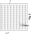
- the light conversion layer 22 includes light passages 30 comprising openings or passage material that does not comprise the phosphor and is light transmissive for the short wavelength light 12.
- the light source 10 is disposed respective to the phosphor conversion component 20 so as to illuminate the light conversion layer 22 with the emitted short wavelength light 12 and to pass the short wavelength light 12 through the light passages 30. This produces mixed light 32 comprising a mixture of the short wavelength light 12 that passes through the light passages 30 and the converted light 24.
- the light source 10 emits the short wavelength light 12 peaked at a peak wavelength of 570 nanometers or shorter. While the LED array 16 is illustrated, more generally the light source 10 may comprise a monochromatic laser light source emitting monochromatic light at an emission line of 570 nanometers or shorter, or may comprise an LED, incandescent lamp, or other polychromatic light source emitting over a visible spectrum that is peaked at a peak wavelength of 570 nanometers or shorter.
- the wavelength of 570 nanometers approximately corresponds to the transition from green light to yellowish light. Mixing strongly green light with phosphor emission in the yellow range (i.e.
- the converted light 24 is likely to produce relatively poor quality white light 32; hence, in some preferred embodiments the light source 10 emits short wavelength light peaked at a peak wavelength of 500 nanometers or shorter (e.g., monochromatic light at an emission line of 500 nanometers or shorter, or polychromatic light over a visible spectrum that is peaked at a peak wavelength of 500 nanometers or shorter).
- the wavelength of 500 nanometers approximately corresponds to the transition from blue light to green light; hence, employing the light source 10 emitting with this specified shorter wavelength characteristic provides more pure bluish light which mixes with the phosphor emission (i.e. converted light 24) to produce a better quality of white light 32.
- the total spectrum of the short wavelength light may comprise the aforementioned visible spectrum further extending into the near ultraviolet - such ultraviolet light is not visible to the human eye.
- the output may be at multiple lines some of which may be in the ultraviolet and hence outside of the visible range.
- the converted light 24 is output by the phosphor of the light conversion layer 22 energized by the short wavelength light 12.
- the converted light 24 preferably has a peak wavelength of 490 nanometers or longer, corresponding to the green, yellow, orange, and red visible spectral regions.
- the converted light 24 is preferably yellowish light, e.g. in the spectral range of roughly 560-590 nanometers.
- the converted light 24 may have two peaks: a first peak at roughly 490-570 nanometers corresponding to greenish light, and a second peak at roughly 580 nanometers or longer corresponding to reddish light.
- the phosphor of the light conversion layer 22 suitably includes separate green and red phosphors in proportions chosen to provide the desired green/red light ratio.
- the precise phosphor composition and the precise spectral composition of the short wavelength light 12 may be chosen to provide white light 32 of a desired color temperature, color rendering index (CRI), or other desired spectral and/or "whiteness" characteristics.
- the light conversion layer 22 has a thickness t as indicated in FIGURE 3 .
- the light conversion layer 22 is of sufficient thickness so that substantially all of the short wavelength light 12 that impinges on the light conversion layer 22 is converted to converted light 24, and/or is partially absorbed by the light conversion layer 22. In this case, substantially no short wavelength light passes through the light conversion layer 22.
- the light penetration depth 8 of the light conversion layer 22 is defined as the depth at which the initial light intensity of the short wavelength light 12 decreases to 1/e 0.368 of its initial value.
- the light conversion layer 22 has a thickness of at least 36, and accordingly the blending of the short wavelength light 12 and the converted light 24 is controlled (almost) entirely by a ratio R of the total area of the light passages 30 compared with the total area of the light conversion layer 22 (including the light passages 30).
- the ratio R is entirely controlled by the geometry of the array of light passages 30 (their number or density, and their size) which can be precisely controlled by suitable techniques such as photolithographic wet or dry etching.
- the short wavelength light 12 that passes through the light passages 30 and the converted light 24 should be well-mixed (i.e. well-blended).
- Various approaches can be employed to promote blending or mixing of the short wavelength light 12 that passes through the light passages 30 and the converted light 24.
- the light passages 30 are relatively small and closely spaced.
- the light passages 30 may optionally have lateral size (e.g.
- the light passages 30 have a lateral dimension that is less than or equal to 20 times the peak wavelength to obtain stronger and/or higher angle diffraction.
- larger-diameter light passages are employed such that no diffraction is obtained, or insufficient diffraction is obtained to provide the desired spatial distribution, and a downstream diffuser or other added optics is provided to shape the light distribution.
- they may have roughened sidewalls that further promote light scattering and consequent blending.
- the light-transmissive substrate 26 can include light scattering particles (e.g., Al2O3 particles dispersed in a glass or plastic substrate), have a roughened backside surface, have a backside surface coated with a light-scattering layer, or otherwise be configured as a light diffuser plate.
- This approach is typically most effective with the orientation shown in FIGURE 1 in which the short wavelength light 12 impinges on the light conversion layer 22, so that the white light 32 then passes through the light-diffusing substrate 26.
- the light passages 30 may be filled with passage material that does not comprise the phosphor and is light transmissive for the short wavelength light 12, and which passage material also includes light scattering particles (e.g., scattering by reflection and/or refractive effects).
- the passage material may be a transparent epoxy filler in which reflective A1203 particles are dispersed so as to scatter the short wavelength light 12 passing through the epoxy-filled light passages 30.
- a white light source 110 emitting the short wavelength light 12 peaked at a peak wavelength of 570 nanometers or shorter (and in some embodiments is peaked at a peak wavelength of 500 nanometers or shorter) is in the form of a laser 110
- a phosphor conversion component 120 is in the form of a rotating reflective phosphor wheel 120 having the light conversion layer 22 disposed on a reflective substrate 126 that is reflective for the short wavelength light 12 and for the converted light.
- the light source 100 is disposed respective to the phosphor conversion component 120 so as to illuminate the light conversion layer 22 with the emitted short wavelength light 12 and to pass the short wavelength light 12 through the light passages 30 and reflect from the reflective substrate 126 back through the light passages 30.
- the illustrative phosphor conversion component 120 comprises a phosphor wheel 120 including a disk 126 arranged to rotate about a central axis 127 of the disk, and the light conversion layer 22 is disposed on at least a portion of the disk, namely in an outer annular region of the disk 126 in the illustrative example of FIGURE 4 .
- the metal disk or "wheel” 126 may, by way of nonlimiting illustration, be made of copper, a copper alloy, an aluminum alloy, silver-coated glass, or so forth.
- the light conversion layer 22 is attached to or coated on an outer perimeter of the wheel 126, that is, disposed at or near the outer rim of the wheel 126.
- the metal wheel 126 is rotated about the central axis 127, for example, by connecting a motor shaft of a motor (not shown) to the central axis 127 and operating the motor to rotate the phosphor wheel 126 in an illustrated clockwise direction CW (counterclockwise rotation is also contemplated).
- the laser 110 applies the short wavelength light 12 to a local region - this is diagrammatically indicated in FIGURE 4 by the laser 110 applying an illustrative pump laser beam spot L.
- the metal wheel 126 rotates the portion of the annular light conversion layer 22 located at the spot L changes, so as to limit (or spread) the generated heat. This can allow for higher power operation.
- FIGURE 5 diagrammatically shows a side sectional view. In the illustrative optical configuration the short wavelength light 12 is applied at an angle and the resulting white light 32 is emitted at a reflective angle as seen in FIGURE 5 .
- Other configurations are contemplated, e.g. using mirrors, lenses, and/or other optical components to configure the light paths.
- the thickness of the light conversion layer 22 should be sufficiently thin to permit short wavelength light 12 that passes through the light passages 30 to reflect back through the (same) passages. In some embodiments it is contemplated to facilitate this by configuring the light passages 30 as elongated slots or slits in the light conversion layer 22, with the long direction of the slots or slits aligned with the angle of incidence/reflection.
- the illustrative phosphor conversion element 120 formed as a phosphor wheel 120 employs a reflective configuration with reflective substrate 126.
- a light transmissive phosphor wheel may be similarly constructed by replacing the reflective substrate 126 with the light transmissive substrate 26 of the embodiment of FIGURES 1-3 .
- This alternative light transmissive phosphor wheel embodiment has an advantage in that the short wavelength light 12 can be applied normal to the surface of the phosphor wheel so that the white light 32 is transmitted light that passes through the phosphor wheel (with some fraction being converted to converted light 24 as described with reference to FIGURE 1 ).
- the substrate 26, 126 may be made of a thermally conductive material.
- a thermally conductive metal plate may be used to remove or spread the heat.
- a thermally conducting transparent polymer material is contemplated to improve heat removal or spreading.
- the light conversion layer 22 may be provided, such as liquid cooling, thermoelectric cooling (applicable for stationary or rotating phosphors for high fluence applications), addition of a dedicated heat sink optionally with forced air cooling, or so forth.
- the light source 10, 110 could be pulsed in time to provide cooling intervals, with the pulsing being at a frequency and duty cycle chosen to be amenable for the particular application.
Landscapes
- Physics & Mathematics (AREA)
- Engineering & Computer Science (AREA)
- Spectroscopy & Molecular Physics (AREA)
- General Engineering & Computer Science (AREA)
- Optics & Photonics (AREA)
- General Physics & Mathematics (AREA)
- Multimedia (AREA)
- Microelectronics & Electronic Packaging (AREA)
- Astronomy & Astrophysics (AREA)
- Projection Apparatus (AREA)
- Optical Filters (AREA)
- Semiconductor Lasers (AREA)
- Led Device Packages (AREA)
- Discharge Lamps And Accessories Thereof (AREA)
- Luminescent Compositions (AREA)
Applications Claiming Priority (3)
| Application Number | Priority Date | Filing Date | Title |
|---|---|---|---|
| US201862675844P | 2018-05-24 | 2018-05-24 | |
| PCT/US2019/032838 WO2019226479A1 (fr) | 2018-05-24 | 2019-05-17 | Dispositif de luminophore à lumière blanche |
| EP19733209.1A EP3803509B1 (fr) | 2018-05-24 | 2019-05-17 | Dispositif de luminophore à lumière blanche |
Related Parent Applications (1)
| Application Number | Title | Priority Date | Filing Date |
|---|---|---|---|
| EP19733209.1A Division EP3803509B1 (fr) | 2018-05-24 | 2019-05-17 | Dispositif de luminophore à lumière blanche |
Publications (1)
| Publication Number | Publication Date |
|---|---|
| EP4488574A2 true EP4488574A2 (fr) | 2025-01-08 |
Family
ID=67003625
Family Applications (2)
| Application Number | Title | Priority Date | Filing Date |
|---|---|---|---|
| EP24214488.9A Withdrawn EP4488574A2 (fr) | 2018-05-24 | 2019-05-17 | Dispositif de luminophore à lumière blanche |
| EP19733209.1A Active EP3803509B1 (fr) | 2018-05-24 | 2019-05-17 | Dispositif de luminophore à lumière blanche |
Family Applications After (1)
| Application Number | Title | Priority Date | Filing Date |
|---|---|---|---|
| EP19733209.1A Active EP3803509B1 (fr) | 2018-05-24 | 2019-05-17 | Dispositif de luminophore à lumière blanche |
Country Status (7)
| Country | Link |
|---|---|
| US (2) | US11421855B2 (fr) |
| EP (2) | EP4488574A2 (fr) |
| JP (2) | JP7394789B2 (fr) |
| KR (2) | KR20250006304A (fr) |
| CN (2) | CN116357903A (fr) |
| TW (2) | TWI810302B (fr) |
| WO (1) | WO2019226479A1 (fr) |
Families Citing this family (2)
| Publication number | Priority date | Publication date | Assignee | Title |
|---|---|---|---|---|
| EP4488574A2 (fr) | 2018-05-24 | 2025-01-08 | Materion Corporation | Dispositif de luminophore à lumière blanche |
| WO2023174818A1 (fr) * | 2022-03-17 | 2023-09-21 | Signify Holding B.V. | Filament à del |
Family Cites Families (29)
| Publication number | Priority date | Publication date | Assignee | Title |
|---|---|---|---|---|
| JP2005353649A (ja) * | 2004-06-08 | 2005-12-22 | Matsushita Electric Ind Co Ltd | Led光源およびその製造方法 |
| JP2007025621A (ja) * | 2005-06-15 | 2007-02-01 | Seiko Instruments Inc | カラー表示装置 |
| US7382091B2 (en) * | 2005-07-27 | 2008-06-03 | Lung-Chien Chen | White light emitting diode using phosphor excitation |
| US20100181591A1 (en) * | 2007-06-29 | 2010-07-22 | Abel Systems Incorporation | Led illumination device using diffraction member |
| KR20090002835A (ko) * | 2007-07-04 | 2009-01-09 | 엘지전자 주식회사 | 질화물계 발광 소자 및 그 제조방법 |
| US20090039375A1 (en) * | 2007-08-07 | 2009-02-12 | Cree, Inc. | Semiconductor light emitting devices with separated wavelength conversion materials and methods of forming the same |
| JP5426848B2 (ja) * | 2008-08-06 | 2014-02-26 | フューチャー ライト リミテッド ライアビリティ カンパニー | 半導体発光装置 |
| US20100117106A1 (en) * | 2008-11-07 | 2010-05-13 | Ledengin, Inc. | Led with light-conversion layer |
| JP5345414B2 (ja) * | 2009-02-19 | 2013-11-20 | スタンレー電気株式会社 | 半導体発光装置 |
| JP5226774B2 (ja) * | 2009-07-27 | 2013-07-03 | 株式会社東芝 | 発光装置 |
| JP2011249573A (ja) * | 2010-05-27 | 2011-12-08 | 三菱電機照明株式会社 | 発光装置及び波長変換シート及び照明装置 |
| US8354784B2 (en) * | 2010-09-28 | 2013-01-15 | Intematix Corporation | Solid-state light emitting devices with photoluminescence wavelength conversion |
| JP2013539229A (ja) * | 2010-09-29 | 2013-10-17 | コーニンクレッカ フィリップス エヌ ヴェ | 波長変換型発光デバイス |
| JP5966501B2 (ja) * | 2012-03-28 | 2016-08-10 | 日亜化学工業株式会社 | 波長変換用無機成形体及びその製造方法、並びに発光装置 |
| WO2013148276A1 (fr) * | 2012-03-31 | 2013-10-03 | Osram Sylvania Inc. | Structure de conversion de longueur d'onde destinée à une source de lumière |
| US20130258638A1 (en) * | 2012-03-31 | 2013-10-03 | Michael Dongxue Wang | Wavelength-converting structure for a light source |
| CN104865783B (zh) * | 2012-04-24 | 2017-05-17 | 深圳市光峰光电技术有限公司 | 光源系统及相关投影系统 |
| DE102012213311A1 (de) * | 2012-07-30 | 2014-01-30 | Osram Gmbh | Projektion mit Halbleiterlichtquellen, Umlenkspiegel und Durchlichtbereichen |
| JPWO2014024218A1 (ja) * | 2012-08-06 | 2016-07-21 | パナソニックIpマネジメント株式会社 | 蛍光体光学素子、その製造方法及び光源装置 |
| JP2014086566A (ja) * | 2012-10-24 | 2014-05-12 | Stanley Electric Co Ltd | 光波長変換装置 |
| JP2014093419A (ja) * | 2012-11-02 | 2014-05-19 | Panasonic Corp | 発光装置の製造方法、発光装置 |
| CN104100898A (zh) * | 2013-04-10 | 2014-10-15 | 鸿富锦精密工业(深圳)有限公司 | 车灯系统 |
| US9797556B2 (en) * | 2013-10-29 | 2017-10-24 | Philips Lighting Holding B.V. | Phosphor based lighting devices and method of generating a light output |
| KR101657954B1 (ko) * | 2014-02-05 | 2016-09-21 | 삼성디스플레이 주식회사 | 백라이트 어셈블리 및 이를 포함하는 표시 장치 |
| US9869442B2 (en) * | 2014-06-26 | 2018-01-16 | Texas Instruments Incorporated | Hybrid illumination system having a blue laser diode, dichroic mirror and yellow transmissive phosphor converter for generating white light |
| DE102016214637B4 (de) * | 2016-08-08 | 2024-11-21 | Coretronic Corporation | Lichtmodul zum Bereitstellen von Licht |
| CN108267913B (zh) * | 2016-12-30 | 2021-06-08 | 中强光电股份有限公司 | 光源模块以及投影装置 |
| CN207049630U (zh) * | 2017-04-05 | 2018-02-27 | 深圳市绎立锐光科技开发有限公司 | 一种荧光模块及光源系统 |
| EP4488574A2 (fr) | 2018-05-24 | 2025-01-08 | Materion Corporation | Dispositif de luminophore à lumière blanche |
-
2019
- 2019-05-17 EP EP24214488.9A patent/EP4488574A2/fr not_active Withdrawn
- 2019-05-17 EP EP19733209.1A patent/EP3803509B1/fr active Active
- 2019-05-17 US US17/040,132 patent/US11421855B2/en active Active
- 2019-05-17 CN CN202310304407.2A patent/CN116357903A/zh active Pending
- 2019-05-17 CN CN201980033921.9A patent/CN112534350B/zh active Active
- 2019-05-17 WO PCT/US2019/032838 patent/WO2019226479A1/fr not_active Ceased
- 2019-05-17 KR KR1020247040789A patent/KR20250006304A/ko active Pending
- 2019-05-17 JP JP2020564929A patent/JP7394789B2/ja active Active
- 2019-05-17 KR KR1020207031474A patent/KR102742165B1/ko active Active
- 2019-05-23 TW TW108117840A patent/TWI810302B/zh active
- 2019-05-23 TW TW112125383A patent/TWI868786B/zh active
-
2022
- 2022-08-08 US US17/883,137 patent/US11624494B2/en active Active
-
2023
- 2023-04-07 JP JP2023062946A patent/JP2023090734A/ja not_active Ceased
Also Published As
| Publication number | Publication date |
|---|---|
| KR102742165B1 (ko) | 2024-12-12 |
| US20210071845A1 (en) | 2021-03-11 |
| TWI810302B (zh) | 2023-08-01 |
| US11421855B2 (en) | 2022-08-23 |
| US20220381422A1 (en) | 2022-12-01 |
| TW202344668A (zh) | 2023-11-16 |
| JP2021524669A (ja) | 2021-09-13 |
| CN112534350A (zh) | 2021-03-19 |
| KR20210015766A (ko) | 2021-02-10 |
| EP3803509A1 (fr) | 2021-04-14 |
| WO2019226479A1 (fr) | 2019-11-28 |
| EP3803509B1 (fr) | 2024-12-18 |
| JP7394789B2 (ja) | 2023-12-08 |
| TW202003788A (zh) | 2020-01-16 |
| CN116357903A (zh) | 2023-06-30 |
| JP2023090734A (ja) | 2023-06-29 |
| KR20250006304A (ko) | 2025-01-10 |
| CN112534350B (zh) | 2023-03-31 |
| US11624494B2 (en) | 2023-04-11 |
| TWI868786B (zh) | 2025-01-01 |
Similar Documents
| Publication | Publication Date | Title |
|---|---|---|
| US9644803B2 (en) | Light source and image projection apparatus | |
| JP5952925B2 (ja) | 半透明外囲体内に配置された発光部を有する光源 | |
| EP2156223B1 (fr) | Système d'éclairage accordable en couleur, lampe et luminaire | |
| US8277064B2 (en) | Light source and illumination system having a predefined external appearance | |
| US9269697B2 (en) | System and methods for warm white LED light source | |
| US9169993B2 (en) | Luminous device | |
| JP5443959B2 (ja) | 照明装置 | |
| US11624494B2 (en) | White light phosphor device | |
| WO2008149265A1 (fr) | Système d'éclairage, collimateur et projecteur | |
| US11422448B2 (en) | High efficiency and uniformity white light generator stimulated by laser | |
| US20250207759A1 (en) | Light source system | |
| JP2014160549A (ja) | 照明装置 |
Legal Events
| Date | Code | Title | Description |
|---|---|---|---|
| PUAI | Public reference made under article 153(3) epc to a published international application that has entered the european phase |
Free format text: ORIGINAL CODE: 0009012 |
|
| STAA | Information on the status of an ep patent application or granted ep patent |
Free format text: STATUS: THE APPLICATION HAS BEEN PUBLISHED |
|
| AC | Divisional application: reference to earlier application |
Ref document number: 3803509 Country of ref document: EP Kind code of ref document: P |
|
| AK | Designated contracting states |
Kind code of ref document: A2 Designated state(s): AL AT BE BG CH CY CZ DE DK EE ES FI FR GB GR HR HU IE IS IT LI LT LU LV MC MK MT NL NO PL PT RO RS SE SI SK SM TR |
|
| STAA | Information on the status of an ep patent application or granted ep patent |
Free format text: STATUS: THE APPLICATION HAS BEEN WITHDRAWN |
|
| 18W | Application withdrawn |
Effective date: 20250203 |