EP4488876A1 - Lecture d'un transpondeur rfid sur un objet dans un dispositif - Google Patents
Lecture d'un transpondeur rfid sur un objet dans un dispositif Download PDFInfo
- Publication number
- EP4488876A1 EP4488876A1 EP24180960.7A EP24180960A EP4488876A1 EP 4488876 A1 EP4488876 A1 EP 4488876A1 EP 24180960 A EP24180960 A EP 24180960A EP 4488876 A1 EP4488876 A1 EP 4488876A1
- Authority
- EP
- European Patent Office
- Prior art keywords
- rfid
- rfid transponder
- antenna
- resonant structure
- wall
- Prior art date
- Legal status (The legal status is an assumption and is not a legal conclusion. Google has not performed a legal analysis and makes no representation as to the accuracy of the status listed.)
- Withdrawn
Links
Images


Classifications
-
- G—PHYSICS
- G06—COMPUTING OR CALCULATING; COUNTING
- G06K—GRAPHICAL DATA READING; PRESENTATION OF DATA; RECORD CARRIERS; HANDLING RECORD CARRIERS
- G06K19/00—Record carriers for use with machines and with at least a part designed to carry digital markings
- G06K19/06—Record carriers for use with machines and with at least a part designed to carry digital markings characterised by the kind of the digital marking, e.g. shape, nature, code
- G06K19/067—Record carriers with conductive marks, printed circuits or semiconductor circuit elements, e.g. credit or identity cards also with resonating or responding marks without active components
-
- G—PHYSICS
- G06—COMPUTING OR CALCULATING; COUNTING
- G06K—GRAPHICAL DATA READING; PRESENTATION OF DATA; RECORD CARRIERS; HANDLING RECORD CARRIERS
- G06K19/00—Record carriers for use with machines and with at least a part designed to carry digital markings
- G06K19/06—Record carriers for use with machines and with at least a part designed to carry digital markings characterised by the kind of the digital marking, e.g. shape, nature, code
- G06K19/067—Record carriers with conductive marks, printed circuits or semiconductor circuit elements, e.g. credit or identity cards also with resonating or responding marks without active components
- G06K19/07—Record carriers with conductive marks, printed circuits or semiconductor circuit elements, e.g. credit or identity cards also with resonating or responding marks without active components with integrated circuit chips
- G06K19/077—Constructional details, e.g. mounting of circuits in the carrier
-
- G—PHYSICS
- G06—COMPUTING OR CALCULATING; COUNTING
- G06K—GRAPHICAL DATA READING; PRESENTATION OF DATA; RECORD CARRIERS; HANDLING RECORD CARRIERS
- G06K7/00—Methods or arrangements for sensing record carriers, e.g. for reading patterns
- G06K7/10—Methods or arrangements for sensing record carriers, e.g. for reading patterns by electromagnetic radiation, e.g. optical sensing; by corpuscular radiation
- G06K7/10009—Methods or arrangements for sensing record carriers, e.g. for reading patterns by electromagnetic radiation, e.g. optical sensing; by corpuscular radiation sensing by radiation using wavelengths larger than 0.1 mm, e.g. radio-waves or microwaves
- G06K7/10297—Methods or arrangements for sensing record carriers, e.g. for reading patterns by electromagnetic radiation, e.g. optical sensing; by corpuscular radiation sensing by radiation using wavelengths larger than 0.1 mm, e.g. radio-waves or microwaves arrangements for handling protocols designed for non-contact record carriers such as RFIDs NFCs, e.g. ISO/IEC 14443 and 18092
-
- G—PHYSICS
- G06—COMPUTING OR CALCULATING; COUNTING
- G06K—GRAPHICAL DATA READING; PRESENTATION OF DATA; RECORD CARRIERS; HANDLING RECORD CARRIERS
- G06K19/00—Record carriers for use with machines and with at least a part designed to carry digital markings
- G06K19/06—Record carriers for use with machines and with at least a part designed to carry digital markings characterised by the kind of the digital marking, e.g. shape, nature, code
- G06K19/067—Record carriers with conductive marks, printed circuits or semiconductor circuit elements, e.g. credit or identity cards also with resonating or responding marks without active components
- G06K19/07—Record carriers with conductive marks, printed circuits or semiconductor circuit elements, e.g. credit or identity cards also with resonating or responding marks without active components with integrated circuit chips
- G06K19/077—Constructional details, e.g. mounting of circuits in the carrier
- G06K19/07749—Constructional details, e.g. mounting of circuits in the carrier the record carrier being capable of non-contact communication, e.g. constructional details of the antenna of a non-contact smart card
-
- G—PHYSICS
- G06—COMPUTING OR CALCULATING; COUNTING
- G06K—GRAPHICAL DATA READING; PRESENTATION OF DATA; RECORD CARRIERS; HANDLING RECORD CARRIERS
- G06K19/00—Record carriers for use with machines and with at least a part designed to carry digital markings
- G06K19/06—Record carriers for use with machines and with at least a part designed to carry digital markings characterised by the kind of the digital marking, e.g. shape, nature, code
- G06K19/067—Record carriers with conductive marks, printed circuits or semiconductor circuit elements, e.g. credit or identity cards also with resonating or responding marks without active components
- G06K19/07—Record carriers with conductive marks, printed circuits or semiconductor circuit elements, e.g. credit or identity cards also with resonating or responding marks without active components with integrated circuit chips
- G06K19/077—Constructional details, e.g. mounting of circuits in the carrier
- G06K19/07749—Constructional details, e.g. mounting of circuits in the carrier the record carrier being capable of non-contact communication, e.g. constructional details of the antenna of a non-contact smart card
- G06K19/07758—Constructional details, e.g. mounting of circuits in the carrier the record carrier being capable of non-contact communication, e.g. constructional details of the antenna of a non-contact smart card arrangements for adhering the record carrier to further objects or living beings, functioning as an identification tag
-
- G—PHYSICS
- G06—COMPUTING OR CALCULATING; COUNTING
- G06K—GRAPHICAL DATA READING; PRESENTATION OF DATA; RECORD CARRIERS; HANDLING RECORD CARRIERS
- G06K19/00—Record carriers for use with machines and with at least a part designed to carry digital markings
- G06K19/06—Record carriers for use with machines and with at least a part designed to carry digital markings characterised by the kind of the digital marking, e.g. shape, nature, code
- G06K19/067—Record carriers with conductive marks, printed circuits or semiconductor circuit elements, e.g. credit or identity cards also with resonating or responding marks without active components
- G06K19/07—Record carriers with conductive marks, printed circuits or semiconductor circuit elements, e.g. credit or identity cards also with resonating or responding marks without active components with integrated circuit chips
- G06K19/077—Constructional details, e.g. mounting of circuits in the carrier
- G06K19/07749—Constructional details, e.g. mounting of circuits in the carrier the record carrier being capable of non-contact communication, e.g. constructional details of the antenna of a non-contact smart card
- G06K19/07771—Constructional details, e.g. mounting of circuits in the carrier the record carrier being capable of non-contact communication, e.g. constructional details of the antenna of a non-contact smart card the record carrier comprising means for minimising adverse effects on the data communication capability of the record carrier, e.g. minimising Eddy currents induced in a proximate metal or otherwise electromagnetically interfering object
-
- G—PHYSICS
- G06—COMPUTING OR CALCULATING; COUNTING
- G06K—GRAPHICAL DATA READING; PRESENTATION OF DATA; RECORD CARRIERS; HANDLING RECORD CARRIERS
- G06K7/00—Methods or arrangements for sensing record carriers, e.g. for reading patterns
- G06K7/10—Methods or arrangements for sensing record carriers, e.g. for reading patterns by electromagnetic radiation, e.g. optical sensing; by corpuscular radiation
- G06K7/10009—Methods or arrangements for sensing record carriers, e.g. for reading patterns by electromagnetic radiation, e.g. optical sensing; by corpuscular radiation sensing by radiation using wavelengths larger than 0.1 mm, e.g. radio-waves or microwaves
- G06K7/10316—Methods or arrangements for sensing record carriers, e.g. for reading patterns by electromagnetic radiation, e.g. optical sensing; by corpuscular radiation sensing by radiation using wavelengths larger than 0.1 mm, e.g. radio-waves or microwaves using at least one antenna particularly designed for interrogating the wireless record carriers
-
- H—ELECTRICITY
- H01—ELECTRIC ELEMENTS
- H01Q—ANTENNAS, i.e. RADIO AERIALS
- H01Q1/00—Details of, or arrangements associated with, antennas
- H01Q1/12—Supports; Mounting means
- H01Q1/22—Supports; Mounting means by structural association with other equipment or articles
- H01Q1/2208—Supports; Mounting means by structural association with other equipment or articles associated with components used in interrogation type services, i.e. in systems for information exchange between an interrogator/reader and a tag/transponder, e.g. in Radio Frequency Identification [RFID] systems
-
- H—ELECTRICITY
- H01—ELECTRIC ELEMENTS
- H01Q—ANTENNAS, i.e. RADIO AERIALS
- H01Q1/00—Details of, or arrangements associated with, antennas
- H01Q1/12—Supports; Mounting means
- H01Q1/22—Supports; Mounting means by structural association with other equipment or articles
- H01Q1/2208—Supports; Mounting means by structural association with other equipment or articles associated with components used in interrogation type services, i.e. in systems for information exchange between an interrogator/reader and a tag/transponder, e.g. in Radio Frequency Identification [RFID] systems
- H01Q1/2216—Supports; Mounting means by structural association with other equipment or articles associated with components used in interrogation type services, i.e. in systems for information exchange between an interrogator/reader and a tag/transponder, e.g. in Radio Frequency Identification [RFID] systems used in interrogator/reader equipment
Definitions
- the invention relates to a device for receiving at least one object with an RFID transponder and a method for reading an RFID transponder on an object in a device according to the preamble of claim 1 or 10.
- An RFID reader uses electromagnetic radiation to stimulate RFID transponders in its reading range to emit the stored information via its antenna, receives the corresponding transponder signals and evaluates them.
- the UHF frequency range (ultra high frequency) is often used for this purpose, as there is an established framework in the ISO 18000-6 standard and transponders can also be read at different distances from a few millimeters to several meters.
- UHF RFID transponders are available in very compact designs and can therefore also be attached to very small objects.
- RFID transponders One area of application for RFID transponders is the most complete documentation of production processes, for example for quality assurance and traceability. There is often a desire to be able to identify the individual components used even after a product has been manufactured. RFID transponders have the advantage that identification is also possible inside a housing, for example, where optical detection would naturally fail.
- the possible communication range for the wireless transmission and reception of the electromagnetic waves of the RFID signals is limited by factors such as free space attenuation, which is determined by country-specific standards, among others. specified maximum permissible transmission power, the sensitivity of the receiver components and the antenna gain of both the RFID reader and the RFID transponder.
- the antenna gain of the RFID transponder plays a particularly important role. This in turn depends not only on the antenna structure but also on the size of the antenna and thus of the RFID transponder. Particularly small RFID transponders are used for the identification of components, which are sometimes very small themselves and whose properties should be influenced as little as possible by the RFID transponder. Their low antenna gain leads to a short reading range, so that the RFID transponder can no longer be read in a larger device or machine. Another problem is metal housings, which prevent or severely impair a radio connection due to their shielding properties.
- Yagi antennas have long been widely used. They are based on the fact that the directivity of a dipole antenna can be focused in one direction if additional rods made of conductive material tuned to the resonance frequency are positioned in front of and behind the dipole antenna. This can then be used on the side of the RFID reader, for example in the US 2009/0174557 A1
- the structures on the RFID transponder side are based on other antenna optimizations, not least for reasons of space.
- the US 2008/0303633 A1 discloses reflectors and directors that are arranged at a distance from an RFID transponder to form Yagi antennas that can double a reading range. However, this still does not solve the problem of being able to read into the interior of a device, especially through a metallic casing, and cannot be used if there is no installation space available inside.
- the US 7 994 962 B1 discloses a method for concentrating RF radiation on an object using reflectors in dimensions that would not be useful for marking assemblies.
- the device for receiving at least one object with an RFID transponder and a method for reading an RFID transponder on an object in a device according to claim 1 or 10.
- the device is, for example, an electronic device, a vehicle, a machine or a part thereof, in particular an enveloping or object-supporting structure or a housing.
- the device has at least one wall, so that an inside and an outside can be distinguished, in particular with regard to the wall.
- the object can be an assembly or component thereof and is marked with an RFID transponder in order to identify it by means of an RFID reading device.
- the RFID transponder has an integrated antenna. Its effective antenna gain and thus the reading range is increased by at least one resonant structure spaced apart from the object and thus also from the RFID transponder with its antenna.
- the invention is based on the basic idea of creating the resonant structure together with the wall. To do this, it is inserted into the wall as a slot structure. If an RFID reader reads from the side of the wall facing away from the RFID transponder, the slot structure effectively acts as an extension of the antenna of the RFID transponder.
- the invention has the advantage that an improvement in the transmitting and receiving properties of the RFID transponder is achieved, which increases the reading range. This makes it possible to communicate with particularly small or compact RFID transponders of various designs, which originally have too small an antenna gain, would be too far away or would not be detected due to shielding effects or attenuation, particularly in the wall.
- the RFID transponders themselves do not have to be subsequently modified for this. Attaching the slot structure requires little effort and no additional material costs.
- the device is preferably designed as a housing or casing.
- the wall preferably closes off the housing in one direction.
- the housing can be the outer housing of an electronic device, but also an inner housing of a component or a module.
- several partial housings are just as conceivable as several objects within a housing, of which one, several or all objects can be marked with one or more RFID transponders.
- the wall is preferably a metallic wall.
- a housing of the device is made entirely of metal.
- An example is the metallic outer skin of a vehicle. Due to the shielding effect, nothing could be read through a metallic wall or casing according to the state of the art.
- the slot structure not only makes the wall effectively transparent for the RFID signal, but also increases the reading range. For example, a metal element with the slot structure can be inserted into a non-metallic wall.
- the resonant structure is preferably tuned to a wavelength of the RFID transponder.
- a structure size of half the wavelength of the RFID transponder can be selected. The necessary size is therefore easy to estimate and the slot structure can remain quite small. For an RFID frequency of 866.5 MHz, for example, it would be around 17.3 cm. This size does not have to be adhered to exactly; the resonance deteriorates with deviations, but a significant, if not the highest possible, increase in range is still achieved.
- the resonant structure is preferably arranged at a distance from the object that is coordinated with a wavelength of the RFID transponder.
- the distance is a quarter of the wavelength of the RFID transponder. Since the arrangement of the object with respect to the wall does not usually adapt to the needs of RFID reading aligns, often only the choice is made as to which wall should be provided with the slot structure at a suitable distance from the object. The optimal distance is then usually only approximately achieved. As in the case of the size of the resonant structure, however, even an approximately ideal distance already leads to an increase in range.
- the object preferably has at least a second resonant structure.
- the second resonant structure interacts with the slot structure to further improve the directivity or increase the range.
- Various designs are conceivable for the second resonant structure, such as wire, an electrical conductor track on a circuit board, a metallized film with an adhesive layer, metallic printing or an integration of metal particles in plastic, in particular by means of 3D printing. If another wall is available in a suitable position or is added, the second resonant structure can also be a slot structure.
- the second resonant structure is preferably arranged as a director between the slot structure and the object.
- the second resonant structure is then located in the propagation path of the RFID signal between the RFID transponder and the RFID reader.
- the second resonant structure is arranged as a reflector in an extension of the connection between the slot structure and the object and thus behind the actual propagation path. It is conceivable to provide a third resonant structure or further resonant structures as directors and/or resonators.
- the system preferably has an RFID reading device to read information from the RFID transponder.
- the RFID reading device preferably comprises at least one internal or external antenna of its own, a transceiver connected to the antenna, and an RFID control and evaluation unit connected to the transceiver.
- the antenna is used by the RFID reading device to send RFID signals to the RFID transponder and/or to receive RFID signals from the RFID transponder. Any combination of a transmitter and receiver is referred to as a transceiver here.
- the RFID control and evaluation unit which has at least one digital computing component, such as a microprocessor, an FPGA (Field Programmable Gate Array), an ASIC (Application Specific Integrated Circuit) or the like, is designed to encode RFID information into the RFID signals and/or to read RFID information from the RFID signals.
- the transceiver and the RFID control and evaluation unit can form a common computing module or at least partially share a computing module. Thanks to the slot structure, the reading range from which the RFID reader can read the RFID transponder is increased.
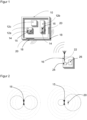
- Figure 1 shows a schematic overview of a device 10, for example an electronic device, with several objects 12a-c or individual components arranged therein, which are at least partially provided with an RFID transponder 14 having an antenna 15.
- An RFID reading device 16 can be arranged outside the device 10 in order to communicate with an RFID transponder 14, in particular to identify an object 12a-c using the RFID transponder 14 attached thereto.
- the read/write range for successful communication between RFID reader 16 and RFID transponder 14 is limited. This range can be limited by shielding effects of walls 18, for example a housing of the device 10, and in the case of a metallic housing, communication may also be completely prevented.
- a resonant structure 20 in the form of a slot structure is provided in at least one wall in order to improve communication. Possible embodiments and the mode of operation of the slot structure are described below with reference to the Figures 2 to 4 explained in more detail.
- the position and size of the resonant structure 20 Depending on the frequency of the RFID communication, there is a respective optimum for the position and size of the resonant structure 20. Since the position of the objects 12a-b and the walls 18 is fixed, an optimal position can only be assumed approximately. The size may also not be ideally implemented due to boundary conditions such as the available space. Nevertheless, the signal attenuation is reduced and communication is improved or even made possible.
- the RFID reading device 16 in turn has an antenna 22, which is designed for the ISM band at around 900 MHz, for example. Instead of the internal antenna 22 shown, an external antenna is also conceivable.
- a transceiver 24 and a control and evaluation unit 26 of the RFID reading device 16 are connected to the antenna 22 in order to evaluate RFID signals received by the antenna 22 or to send information as RFID signals to the RFID transponder 14.
- the control and evaluation unit 26 is preferably connected to a wired or wireless interface (not shown) in order to exchange data, carry out parameterizations and the like.
- the functioning of an RFID reading device for example for the UHF frequency range (ultra high frequency) according to the ISO 18000-6 standard, is known per se and is therefore not explained in more detail.
- Figure 2 shows a schematic representation of the antenna gain of an antenna 15 changed by a resonant structure 20.
- the antenna 15 alone is shown on the left and the antenna with the resonant structure 20 is shown on the right.
- a wire with an extension of approximately half a wavelength of 17.3 cm can be selected as the resonant structure 20 and positioned at a distance of a quarter of the wavelength from the antenna 15.
- a favorable effect also occurs if these specifications are only approximately met and, for example, a wire with a length of 16 cm is used.
- the directivity is significantly improved by the resonant structure 20 when, in the example of the right side of Figure 2 should be read from the right.
- FIGs 3a-f show schematic representations of an antenna 15 of an RFID transponder 14 and an antenna 22 of an RFID reader 16 with different constellations of resonant structures.
- Figure 3a the situation of only the two antennas without additional resonant structure is shown.
- Figure 3b From the perspective of the antenna 22 of the RFID reading device 16, a resonant structure 20 is arranged behind the antenna 15 of the RFID transponder 14, which thus takes on the function of a reflector.
- Figure 3c the order is reversed and the resonant structure 20 is arranged in front of the antenna 15, thus acting as a director.
- Figures 3d-f show constellations in which the resonant structure 20 is supplemented by at least one further resonant structure 20a-b.
- Figure 3d shows an arrangement with two resonant structures 20, 20a in front of the antenna 15, which thus both function as directors.
- Figure 3e shows a resonant structure 20 in front of the antenna 15 and a resonant structure 20a behind the antenna 15 and thus a combination of a director and a reflector.
- Figure 3f is an example of combinations with even more resonant structures to the arrangement of the Figure 3e
- Another resonant element 20b is added as a second director.
- Figure 4 shows a schematic representation of a resonant structure 20 designed as a slot structure, which is introduced into the wall 18.
- the slot structure functions as a slot radiator or slot antenna and is thus also able to improve the reading range or to enable communication into a metal-encased device 10 in the first place.
- the geometric requirements for the slot or the recess in terms of extent and position are the same as already discussed.
- the device 10 is a vehicle, in particular a car.
- Components such as a seat or a control unit are installed as objects 12a-b carrying the RFID transponders 14. These components should still be identifiable by reading the RFID transponders 14 even after the vehicle has been assembled. Due to the installation position, this would be possible according to the state of the art with a RFID reading device 16, which is arranged in front of the vehicle, is not possible.
- a resonant structure 20 can now be attached to a side window or plastic cover as a metal part with the slot structure. It is even simpler to introduce the slot structure into the metallic outer skin, whereby the slot structure can then be filled with plastic, for example, so as not to disturb the overall visual impression of the vehicle.
- the slot structure makes it possible to continue to identify the components of the finished vehicle from outside by reading the RFID transponders 14.
- the device 10 is an electrical appliance, in particular a large electrical appliance such as a flat screen TV, a vacuum cleaner or a washing machine.
- a compact RFID transponder 14 was integrated into the device 10, which is intended to make it possible to identify a component or the entire electrical appliance.
- the size of the transponder would only allow reading at a short distance, such as less than 10 cm.
- identification from the outside should be possible without dismantling a housing.
- a slot structure is introduced into a circuit board above the transponder as a resonant structure 20 or a metal element with the slot structure is arranged there, alternatively the slot structure is introduced into a housing wall, in particular a metallic one. Due to the thus improved radiation characteristics of the RFID transponder 14, identification can now take place from the outside. A marking can also be attached to the housing to show the user from which position of an RFID reading device 16 the reading of the RFID transponder 14 is particularly easy.
Landscapes
- Engineering & Computer Science (AREA)
- Physics & Mathematics (AREA)
- General Physics & Mathematics (AREA)
- Theoretical Computer Science (AREA)
- Health & Medical Sciences (AREA)
- Toxicology (AREA)
- Computer Hardware Design (AREA)
- Electromagnetism (AREA)
- Microelectronics & Electronic Packaging (AREA)
- Artificial Intelligence (AREA)
- Computer Vision & Pattern Recognition (AREA)
- General Health & Medical Sciences (AREA)
- Computer Networks & Wireless Communication (AREA)
- Computer Security & Cryptography (AREA)
- Aerials With Secondary Devices (AREA)
- Near-Field Transmission Systems (AREA)
Applications Claiming Priority (1)
| Application Number | Priority Date | Filing Date | Title |
|---|---|---|---|
| DE102023117578.5A DE102023117578A1 (de) | 2023-07-04 | 2023-07-04 | Lesen eines RFID-Transponders auf einem Objekt in einer Vorrichtung |
Publications (1)
| Publication Number | Publication Date |
|---|---|
| EP4488876A1 true EP4488876A1 (fr) | 2025-01-08 |
Family
ID=91469854
Family Applications (1)
| Application Number | Title | Priority Date | Filing Date |
|---|---|---|---|
| EP24180960.7A Withdrawn EP4488876A1 (fr) | 2023-07-04 | 2024-06-10 | Lecture d'un transpondeur rfid sur un objet dans un dispositif |
Country Status (4)
| Country | Link |
|---|---|
| US (1) | US12554959B2 (fr) |
| EP (1) | EP4488876A1 (fr) |
| CN (1) | CN119272780A (fr) |
| DE (1) | DE102023117578A1 (fr) |
Citations (14)
| Publication number | Priority date | Publication date | Assignee | Title |
|---|---|---|---|---|
| US2518371A (en) * | 1946-03-22 | 1950-08-08 | Csf | Method for the direct modulation of an ultra-short wave transmitter |
| WO2000021030A1 (fr) | 1998-10-06 | 2000-04-13 | Intermec Ip Corp. | Transpondeur a identification de frequences radioelectriques a caracteristiques rf ameliorees |
| US6320509B1 (en) | 1998-03-16 | 2001-11-20 | Intermec Ip Corp. | Radio frequency identification transponder having a high gain antenna configuration |
| US6441740B1 (en) | 1998-02-27 | 2002-08-27 | Intermec Ip Corp. | Radio frequency identification transponder having a reflector |
| US20020167450A1 (en) * | 1999-11-18 | 2002-11-14 | Siemens Ag | Mobile data carrier including a transponder having a surface wave component and a slot antenna |
| US20080303633A1 (en) | 2007-06-07 | 2008-12-11 | The Hong Kong University Of Science And Technology | High gain rfid tag antennas |
| US20090174557A1 (en) | 2008-01-03 | 2009-07-09 | Intermec Ip Corp. | Compact flexible high gain antenna for handheld rfid reader |
| US7994962B1 (en) | 2007-07-17 | 2011-08-09 | Drosera Ltd. | Apparatus and method for concentrating electromagnetic energy on a remotely-located object |
| US20130313328A1 (en) * | 2012-05-25 | 2013-11-28 | Omni-Id Cayman Limited | Shielded Cavity Backed Slot Decoupled RFID TAGS |
| EP2677475A1 (fr) * | 2012-06-22 | 2013-12-25 | Join Yiuh Industry Co., Ltd. | Procédé de fabrication de produit métallique à identification par radiofréquence à longue portée et structure d'arrière-plan de l'invention associée |
| US20170277922A1 (en) | 2016-03-28 | 2017-09-28 | Tai-Hwa Liu | Mobile wireless antenna system for rfid application |
| US20170293832A1 (en) * | 2017-06-27 | 2017-10-12 | Daniel Pai | License plate radio electronic identifier |
| US20170344772A1 (en) * | 2016-05-31 | 2017-11-30 | Sick Ag | Rfid reading apparatus for shelf occupancy detection |
| US20190103682A1 (en) * | 2017-09-30 | 2019-04-04 | Intel IP Corporation | Compact radio frequency (rf) communication modules with endfire and broadside antennas |
Family Cites Families (5)
| Publication number | Priority date | Publication date | Assignee | Title |
|---|---|---|---|---|
| US6703935B1 (en) * | 2001-05-14 | 2004-03-09 | Amerasia International Technology, Inc. | Antenna arrangement for RFID smart tags |
| US20110068987A1 (en) * | 2009-08-05 | 2011-03-24 | New Jersey Microsystems. Inc | Multiband RFID tag |
| US8439272B2 (en) * | 2010-11-15 | 2013-05-14 | Neoid Limited | Resonant circuit structure and RF tag having same |
| US10566962B2 (en) | 2017-10-02 | 2020-02-18 | Cirrus Logic, Inc. | Pulse-width modulation |
| US20240005122A1 (en) * | 2022-06-29 | 2024-01-04 | Nxp B.V. | Radio frequency identification tag with antenna and passive reflector |
-
2023
- 2023-07-04 DE DE102023117578.5A patent/DE102023117578A1/de active Pending
-
2024
- 2024-06-10 EP EP24180960.7A patent/EP4488876A1/fr not_active Withdrawn
- 2024-06-21 CN CN202410812168.6A patent/CN119272780A/zh active Pending
- 2024-07-03 US US18/763,404 patent/US12554959B2/en active Active
Patent Citations (14)
| Publication number | Priority date | Publication date | Assignee | Title |
|---|---|---|---|---|
| US2518371A (en) * | 1946-03-22 | 1950-08-08 | Csf | Method for the direct modulation of an ultra-short wave transmitter |
| US6441740B1 (en) | 1998-02-27 | 2002-08-27 | Intermec Ip Corp. | Radio frequency identification transponder having a reflector |
| US6320509B1 (en) | 1998-03-16 | 2001-11-20 | Intermec Ip Corp. | Radio frequency identification transponder having a high gain antenna configuration |
| WO2000021030A1 (fr) | 1998-10-06 | 2000-04-13 | Intermec Ip Corp. | Transpondeur a identification de frequences radioelectriques a caracteristiques rf ameliorees |
| US20020167450A1 (en) * | 1999-11-18 | 2002-11-14 | Siemens Ag | Mobile data carrier including a transponder having a surface wave component and a slot antenna |
| US20080303633A1 (en) | 2007-06-07 | 2008-12-11 | The Hong Kong University Of Science And Technology | High gain rfid tag antennas |
| US7994962B1 (en) | 2007-07-17 | 2011-08-09 | Drosera Ltd. | Apparatus and method for concentrating electromagnetic energy on a remotely-located object |
| US20090174557A1 (en) | 2008-01-03 | 2009-07-09 | Intermec Ip Corp. | Compact flexible high gain antenna for handheld rfid reader |
| US20130313328A1 (en) * | 2012-05-25 | 2013-11-28 | Omni-Id Cayman Limited | Shielded Cavity Backed Slot Decoupled RFID TAGS |
| EP2677475A1 (fr) * | 2012-06-22 | 2013-12-25 | Join Yiuh Industry Co., Ltd. | Procédé de fabrication de produit métallique à identification par radiofréquence à longue portée et structure d'arrière-plan de l'invention associée |
| US20170277922A1 (en) | 2016-03-28 | 2017-09-28 | Tai-Hwa Liu | Mobile wireless antenna system for rfid application |
| US20170344772A1 (en) * | 2016-05-31 | 2017-11-30 | Sick Ag | Rfid reading apparatus for shelf occupancy detection |
| US20170293832A1 (en) * | 2017-06-27 | 2017-10-12 | Daniel Pai | License plate radio electronic identifier |
| US20190103682A1 (en) * | 2017-09-30 | 2019-04-04 | Intel IP Corporation | Compact radio frequency (rf) communication modules with endfire and broadside antennas |
Also Published As
| Publication number | Publication date |
|---|---|
| DE102023117578A1 (de) | 2025-01-09 |
| US20250013849A1 (en) | 2025-01-09 |
| CN119272780A (zh) | 2025-01-07 |
| US12554959B2 (en) | 2026-02-17 |
Similar Documents
| Publication | Publication Date | Title |
|---|---|---|
| EP2811575B1 (fr) | Antenne | |
| DE10192529B4 (de) | Antennensystem | |
| EP2490150B1 (fr) | Tunnel de lecture RFID et procédé de lecture de transpondeurs RFID | |
| EP1990755B1 (fr) | Procédé de fonctionnement d'une étiquette RFID dotée d'une localisation exacte | |
| EP1336158A1 (fr) | Support de donnees sans contact | |
| DE202010008162U1 (de) | RFID-Lesevorrichtung | |
| WO2018050420A1 (fr) | Ensemble antenne | |
| DE102014118391A1 (de) | Vorrichtung zur Übertragung von Signalen aus einem Metall-Gehäuse | |
| WO2004017093A1 (fr) | Detecteur d'emission et de reception de signaux electromagnetiques | |
| DE102007029083A1 (de) | Kartendatenträger mit Detektierplättchen | |
| EP3511684A1 (fr) | Appareil de mesure de niveau de remplissage | |
| EP3669300B1 (fr) | Dispositif et procédé pour émettre et recevoir des données d'une étiquette rfid passive | |
| DE102008018776A1 (de) | Lager, insbesondere Wälz- oder Gleitlager oder Linearführung, mit einem Transponder | |
| EP4488876A1 (fr) | Lecture d'un transpondeur rfid sur un objet dans un dispositif | |
| EP1886263B1 (fr) | Systeme comportant un transpondeur et un element metallique | |
| DE202023103690U1 (de) | Lesen eines RFID-Transponders auf einem Objekt in einer Vorrichtung | |
| EP2618425B1 (fr) | Recouvrement d'antenne | |
| WO2007131879A1 (fr) | Dispositif d'essai présentant une antenne à double bande hf-/uhf destiné à tester des transpondeurs rfid dans un dispositif de production | |
| DE102006062308A1 (de) | Passives Detektierplättchen | |
| DE102018122423A1 (de) | Vorrichtung zur Übertragung von Signalen aus einem zumindest teilweise metallischen Gehäuse | |
| EP2790269B1 (fr) | Antenne | |
| EP1936740B1 (fr) | Système et procédé de mesure d'une information de mouvement d'après le principe Doppler | |
| DE102023124739B3 (de) | Vorrichtung zum Beschreiben und/oder Auslesen von RFID-Tags | |
| EP3808577B1 (fr) | Pneumatique | |
| DE102015214172B4 (de) | Vorrichtung zur Objekterfassung |
Legal Events
| Date | Code | Title | Description |
|---|---|---|---|
| PUAI | Public reference made under article 153(3) epc to a published international application that has entered the european phase |
Free format text: ORIGINAL CODE: 0009012 |
|
| STAA | Information on the status of an ep patent application or granted ep patent |
Free format text: STATUS: THE APPLICATION HAS BEEN PUBLISHED |
|
| AK | Designated contracting states |
Kind code of ref document: A1 Designated state(s): AL AT BE BG CH CY CZ DE DK EE ES FI FR GB GR HR HU IE IS IT LI LT LU LV MC ME MK MT NL NO PL PT RO RS SE SI SK SM TR |
|
| STAA | Information on the status of an ep patent application or granted ep patent |
Free format text: STATUS: THE APPLICATION IS DEEMED TO BE WITHDRAWN |
|
| 18D | Application deemed to be withdrawn |
Effective date: 20250709 |