EP4489048A1 - Disjoncteur à air ayant un couvercle d'arc - Google Patents
Disjoncteur à air ayant un couvercle d'arc Download PDFInfo
- Publication number
- EP4489048A1 EP4489048A1 EP23763636.0A EP23763636A EP4489048A1 EP 4489048 A1 EP4489048 A1 EP 4489048A1 EP 23763636 A EP23763636 A EP 23763636A EP 4489048 A1 EP4489048 A1 EP 4489048A1
- Authority
- EP
- European Patent Office
- Prior art keywords
- circuit breaker
- arc
- air circuit
- arc cover
- extinguishing unit
- Prior art date
- Legal status (The legal status is an assumption and is not a legal conclusion. Google has not performed a legal analysis and makes no representation as to the accuracy of the status listed.)
- Pending
Links
Images


Classifications
-
- H—ELECTRICITY
- H01—ELECTRIC ELEMENTS
- H01H—ELECTRIC SWITCHES; RELAYS; SELECTORS; EMERGENCY PROTECTIVE DEVICES
- H01H31/00—Air-break switches for high tension without arc-extinguishing or arc-preventing means
- H01H31/02—Details
- H01H31/04—Interlocking mechanisms
- H01H31/06—Interlocking mechanisms for interlocking between casing, cover, or protective shutter and mechanism for operating contacts
-
- H—ELECTRICITY
- H01—ELECTRIC ELEMENTS
- H01H—ELECTRIC SWITCHES; RELAYS; SELECTORS; EMERGENCY PROTECTIVE DEVICES
- H01H9/00—Details of switching devices, not covered by groups H01H1/00 - H01H7/00
- H01H9/30—Means for extinguishing or preventing arc between current-carrying parts
- H01H9/34—Stationary parts for restricting or subdividing the arc, e.g. barrier plate
- H01H9/342—Venting arrangements for arc chutes
-
- H—ELECTRICITY
- H01—ELECTRIC ELEMENTS
- H01H—ELECTRIC SWITCHES; RELAYS; SELECTORS; EMERGENCY PROTECTIVE DEVICES
- H01H33/00—High-tension or heavy-current switches with arc-extinguishing or arc-preventing means
- H01H33/02—Details
- H01H33/04—Means for extinguishing or preventing arc between current-carrying parts
- H01H33/08—Stationary parts for restricting or subdividing the arc, e.g. barrier plate
-
- H—ELECTRICITY
- H01—ELECTRIC ELEMENTS
- H01H—ELECTRIC SWITCHES; RELAYS; SELECTORS; EMERGENCY PROTECTIVE DEVICES
- H01H9/00—Details of switching devices, not covered by groups H01H1/00 - H01H7/00
- H01H9/30—Means for extinguishing or preventing arc between current-carrying parts
- H01H9/34—Stationary parts for restricting or subdividing the arc, e.g. barrier plate
- H01H2009/348—Provisions for recirculation of arcing gasses to improve the arc extinguishing, e.g. move the arc quicker into the arcing chamber
Definitions
- the present invention relates to an air circuit breaker, and more particularly, to an air circuit breaker having an arc cover capable of preventing a secondary accident caused by arc generation.
- circuit breakers block currents and protect power systems and load devices when devices that receive power from transmission and substation systems or lines are opened or closed or when accidents such as overloads or short circuits occur.
- the circuit breaker according to the related art is provided with a movable contact and a stationary contact in contact with the movable contact, the current flows in the line when the movable contact is in contact with the stationary contact, and the movable contact is separated from the stationary contact to block the current in the line when a high current flows in the line due to the accident.
- the air circuit breaker blocks a fault current within a short period of time when a short circuit occurs for user safety and system integrity.
- a conductive arc inside an arc extinguishing unit is discharged to the outside of the arc extinguishing unit, a conductive hot gas is discharged together and electrified with an adjacent switchboard or the like, and thus secondary accidents occur.
- the present invention is created to solve the above problems, and the present invention is directed to providing an air circuit breaker having an arc cover, in which a high-temperature gas primarily extinguished by an arc extinguishing unit stays inside a chamber having a certain space so that conductivity is decreased when the gas is discharged and is then induced to be discharged, thereby preventing secondary accidents in advance.
- an air circuit breaker having an arc cover includes an operation unit in which arc is generated by operating a movable contact with respect to a stationary contact, an arc extinguishing unit that is installed on an upper side of the operation unit and primarily extinguish the arc, and an arc cover which is installed on an upper side of the arc extinguishing unit, has a chamber formed such that a high-temperature gas passing through the arc extinguishing unit stays therein, and has at least one guide panel partitioning an interior of the chamber into a plurality of parts and having an opening on one side thereof, and in which the high-temperature gas is discharged to an outlet in a first direction along a passage guided by the guide panel.
- the arc cover may be formed such that a cross-sectional area of an inlet through which the high-temperature gas is introduced is greater than a cross-sectional area of the outlet.
- the guide panel of the arc cover may be installed horizontally or inclined with respect to a horizontal plane.
- An inner rib may be vertically formed in an inner side surface of the arc cover and the guide panel.
- the inner rib may be formed in an arch shape.
- the inner rib may be formed as a plurality of inner ribs, and each inner rib may protrude at a different height.
- An outer rib may be vertically formed on an outer side surface of the arc cover, and the outer rib and the inner rib may be formed at positions corresponding to each other.
- the guide panel may be formed as a plurality of guide panels.
- the outlet in the first direction may be formed on a front upper side or both side surfaces of the air circuit breaker.
- a sealing member may be installed between the arc extinguishing unit and the arc cover to prevent the high-temperature gas from leaking.
- a shield panel in which a plurality of through-holes are formed, may be installed between the arc extinguishing unit and the arc cover to control a flow rate of the gas.
- the shield panel may be coupled to or integrally formed with a lower end of the arc cover.
- a closed part of the shield panel in which the through-holes are not formed may be positioned below an opening formed by the guide panel.
- an air circuit breaker having an arc cover according to the present invention may be provided with an arc cover having a guide panel so that flow of a fluid is changed, thereby sufficiently removing conductivity of gas.
- gas is guided inside a chamber of the arc cover by a shield panel, a guide panel, and an arch-shaped inner rib and flows for a sufficient time, and thus secondary accidents caused by conductivity of the gas can be prevented in advance.
- a case in which a component is present on a "front side,” a “rear side,” an “upper side,” or a “lower side” of another component includes a case in which the component is disposed on the "front side,” the “rear side,” the “upper side,” or the “lower side” in direct contact with the another component as well as a case in which still another component is disposed therebetween, unless otherwise specified.
- a case in which a first component is "connected" to a second component includes a case in which the first component and the second component are indirectly connected to each other as well as a case in which the first component and the second component are directly connected to each other unless otherwise specified.
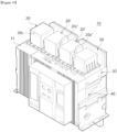
- an air circuit breaker 10 having an arc cover includes an operation unit 40, an arc extinguishing unit 30, and an arc cover 20.
- the air circuit breaker 10 has a generally rectangular parallelepiped shape, and a case 11 is provided outside the air circuit breaker 10 to protect internal components.
- the operation unit 40 equipped with a stationary contact and a movable contact controls a current, and in this case, an arc is generated in this portion.
- the arc extinguishing unit 30 for primarily extinguishing the generated arc is provided on an upper side of the operation unit 40 provided inside the case 11.
- the arc cover 20 for secondarily managing a high-temperature gas that rises from the arc extinguishing unit 30 is fixedly installed at an upper end of the arc extinguishing unit 30, herein, at a position corresponding to an upper surface of the case 11.
- an outlet 20c is formed in a forward direction of the arc cover 20 so that the gas managed by the arc cover 20 may be discharged to the front side.
- a busbar 50 is installed behind the case 11, and in this case, it is not preferable that the gas be discharged to the rear side.
- the air circuit breaker 10 may be classified into a so-called fixed type air circuit breaker and a so-called draw-out type air circuit breaker.
- the fixed type air circuit breaker is a type in which internal components are fixedly installed and difficult to replace
- the draw-out type air circuit breaker is known to be a type in which various components may be draw-out and replaced depending on states of the internal components.
- secondary accidents may occur more frequently.
- the fixed type air circuit breaker it is very effective to apply the present invention.
- the operation unit 40 may generate an arc as the movable contact is operated with respect to the stationary contact.
- the configuration of the operation unit 40 is the same as the related art, and thus herein, a detailed description thereof will be omitted.
- the arc extinguishing unit 30 is installed on an upper side of the operation unit 40 and primarily extinguishes the arc.
- a support plate 33 is installed on a side surface of the arc extinguishing unit 30, and an arc guide is installed on a lower side of the arc extinguishing unit 30.
- An upper cover panel 36 is installed on an upper side of the arc extinguishing unit 30, and a plurality of grids 32 vertically standing are installed at regular intervals inside the arc extinguishing unit 30.
- the arc generated in the operation unit 40 is extinguished while passing between the grids 32 of the arc extinguishing unit 30 and passes through a through-hole 36a of the upper cover panel 36 and rises into a chamber 20a of the arc cover 20.
- the arc is primarily extinguished by the arc extinguishing unit 30, and the high-temperature gas moves upward to the chamber 20a of the arc cover 20.
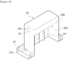
- the arc cover 20 is installed on the upper side of the arc extinguishing unit 30, the chamber 20a is formed so that the high-temperature gas passing through the arc extinguishing unit 30 may stay, at least one guide panel 23 by which an interior of the chamber 20a is partitioned into a plurality of parts and in which an opening is formed on one side thereof may be provided, and the high-temperature gas may be discharged to the outlet 20c formed on a front surface of the air circuit breaker 10 along a passage guided by the guide panel 23.
- the arc cover 20 is generally formed in a rectangular parallelepiped shape, and a lower surface thereof is open so that the high-temperature gas may be introduced into the chamber 20a due to a rising pressure thereof, may pass through a passage according to guide of the guide panel 23, and may be exhausted to the outlet 20c formed on the front surface.
- one guide panel 23 is installed, but a plurality of guide panels 23 may be formed.
- the arc cover 20 may be formed such that a cross-sectional area of an inlet through which the high-temperature gas is introduced is greater than a cross-sectional area of the outlet 20c. That is, a cross-sectional area through which the high-temperature gas introduced from the lower arc extinguishing unit 30 passes may be formed to be larger than a cross-sectional area of the outlet 20c through which the gas is discharged from the arc cover 20.
- this cross-sectional area ratio may be optimized through an experiment in consideration of both a design condition, the temperature of the arc generated in the internal operation unit 40, or the like.
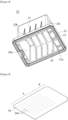
- the shield panel 34 is installed below the upper cover panel 36, the shield panel 34 is installed between the arc extinguishing unit 30 and the arc cover 20, and a plurality of through-holes 34a are formed only in a portion of the shield panel 34. That is, the shield panel 34 may include an open part A in which the plurality of through-holes 34a are formed, and a closed part B in which the through-holes 34a are not formed.
- the number or shape of the through-holes 34a may be designed according to design of a cross-sectional area of the shield panel 34, through which the high-temperature gas passes.
- the closed part B may be positioned below an opening 20b formed by the guide panel 23. As the guide panel 23 and the shield panel 34 are arranged and formed in this way, flow of the high-temperature gas as illustrated in FIG. 6 may be induced.
- the shield panel 34 is described as a component of the arc extinguishing unit, but the shield panel 34 may be designed in a structure that is not coupled to the inside of the arc extinguishing unit but is coupled to a lower end of the arc cover 20 in terms of a position of the shield panel according to another embodiment. That is, it is obvious that the shield panel 34 may be designed in a structure that is coupled to or integrated with a lower end of the chamber 20a of the arc cover 20.
- an inner rib 24 may be vertically formed in an inner side surface of the arc cover 20 and the guide panel 23. A plurality of inner ribs 24 may be formed at regular intervals.
- the inner rib 24 may be formed in an arch shape. That is, a corner of the arc cover 20 may be formed to protrude further inward than other parts.
- an outer rib 21 may be vertically formed on an outer side surface of the arc cover 20, and the outer rib 21 and the inner rib 24 may be formed at positions corresponding to each other.
- the inner rib 24 and the outer rib 21 may be formed at the corresponding positions, which may more firmly cope with pressure of the gas applied to the side surface.
- a sealing member may be installed between the arc extinguishing unit 30 and the arc cover 20 to prevent leakage of the high-temperature gas.
- a groove 22a for the sealing member may be formed on a lower surface of a flange part of the arc cover 20, and the sealing member made of rubber may be inserted into the groove 22a and then assembled with a body and a piece of the arc extinguishing unit 30.
- the high-temperature gas is prevented from leaking between the assembled portions of the arc extinguishing unit 30 and the arc cover 20.
- the arc extinguishing unit 30 may be assembled in a manner of being inserted into the case 11 of the air circuit breaker 10, and the arc cover 20 may be assembled to form the internal chamber 20a in an upper space thereof in a state in which the arc extinguishing unit 30 is inserted.
- the outlet 20c is formed on a front upper side of the arc cover 20
- a probability that the gas exhausted from the arc cover 20 comes into contact with the rear busbar 50 is very low.
- a cabinet is installed to be spaced a predetermined distance from the case 11 of the air circuit breaker 10, but the gas discharged to the arc cover 20 has already lost conductivity, and thus secondary accidents can be prevented.
- FIGS. 3 and 4 a state in which the arc cover 20 and the arc extinguishing unit 30 of the air circuit breaker 10 are assembled with each other is illustrated.
- the arc extinguishing unit 30 is positioned on a lower side, and the arc cover 20 is positioned on an upper side.
- the high-temperature gas extinguished by the arc extinguishing unit 30 has a high temperature and thus moves upward even without a separate pressure providing unit. That is, the gas passing through the arc extinguishing unit 30 rises to the internal chamber 20a of the arc cover 20.
- the arc cover 20 and the arc extinguishing unit 30 are assembled by pieces.
- the sealing member may be interposed therebetween, and the arc cover 20 and the arc extinguishing unit 30 may be assembled by the pieces.
- an assembly connection portion between the arc extinguishing unit 30 and the arc cover 20 is sealed to prevent leakage of the gas.
- the support plates 33 are assembled on both surfaces of the frame 31, and support the plurality of grids 32 installed therebetween. In this location, the arc is extinguished and thus a lot of heat and pressure are generated.
- the shield panel 34 may be installed at an upper side of the grids 32 in the frame 31 of the arc extinguishing unit 30.
- the plurality of through-holes 34a may be formed in the shield panel 34, and the amount of high-temperature gas supplied to the arc cover 20 may be determined according to the design of the through-holes 34a.
- the shield panel 34 includes the open part A and the closed part B as described above.
- a plurality of mesh members 35 are installed on an upper side of the shield panel 34, and the upper cover panel 36 is assembled with the frame 31 on the upper side of the mesh members 35.
- the through-hole 36a may be also formed in the upper cover panel 36, allow the amount of air to be controlled, and serve to support components assembled in a lower portion from the upper side.
- the arc cover 20 is placed on the upper cover panel 36, and the flange 22 of the arc cover 20 is piece-assembled with the upper cover panel 36 using a piece hole 22b.
- the plurality of outer ribs 21 may be formed on the side surface of the arc cover 20 to help reinforce a strength of the side surface of the arc cover 20, and the outlet 20c may be formed on a front surface of the arc cover 20 to exhaust the gas that has lost conductivity to the outside of the chamber 20a of the arc cover 20.
- the high-temperature gas flowing upward from the arc extinguishing unit 30 rises to the front side, that is, only the part A and the part B is closed, and thus the gas cannot pass therethrough. That is, the gas of the arc extinguishing unit 30 passes through the shield panel 34, does not pass through the closed part B, passes through only the open part A in which the through-hole 34a is formed, and thus rises into the chamber 20a.
- the gas rises vertically along the inner rib 24 and then meets the guide panel 23.
- the high-temperature gas does not move directly rearward along the guide panel 23 but moves beyond the arch-shaped inner rib 24.
- the gas passes beyond all the inner ribs 24, passes through the opening 20b formed by the guide panel 23 and a rear surface of a body of the arc cover 20, moves forward again by pressure, and is then exhausted to the outlet 20c.
- the high-temperature gas flows along a passage as illustrated by an arrow in FIG. 6 .
- the high-temperature gas may not be directly discharged to the outside of the arc cover 20 but may flow along a passage that is bent several times, then be exhausted, and thus be exhausted while conductivity thereof is lost.
- the flow of a fluid illustrated in FIG. 6 may be achieved by the shield panel 34 and the guide panel 23, and the inner ribs 24 may act as a cause of helping this flow.
- FIGS. 7 and 8 an outer appearance of the arc cover 20 is illustrated.
- the plurality of outer ribs 21 are formed on both side surfaces of the arc cover 20, and as described above, the outer rib 21 and the inner rib 24 are formed at the corresponding positions.
- the shape of the arc cover 20 may be firmly maintained, and thus the arc cover 20 may withstand the pressure of the gas rising from the arc extinguishing unit 30.
- the groove 22a is formed in the flange 22 of the arc cover 20, and the sealing member is assembled together.
- outlets 20c' of an arc cover 20' are formed on both side surfaces of the arc cover 20'.
- the outlets 20c are formed on front surfaces of the arc covers 20 at both ends, which is similar to the above-described embodiment, and the outlets 20c' are formed on both side surfaces of the two arc covers 20' at a center thereof. That is, this is a structure in which the extinguished gas may be discharged in wider directions than a case in which the entire arc cover exhausts the gas to the front surface.
- the arc cover 20 may have a plurality of inner ribs 24', and each inner rib 24' may protrude at a different height.
- the four inner ribs 24' are formed in an arch shape and have different protruding heights. In this way, as the inner ribs 24' are formed at different heights, the passage of the gas may be made more complicated, and accordingly, an exhaust time may be increased, thereby helping to lose the conductivity of the gas.
- the heights of the inner ribs in the vertical direction are changed, but it is obvious that the protrusion lengths of the inner ribs protruding from the side surfaces may be changed and applied.
- the guide panel 23 of the arc cover 20 is installed in a horizontal direction, but herein, the guide panel 23 may be installed to be inclined with respect to a horizontal plane.
- the guide panel 23' is inclined forward
- the guide panel 23" is inclined rearward. Efficiency according to the inclination of each of the guide panels 23' and 23" can be optimized through an experiment in consideration of heights of the guide panels 23' and 23", a height or cross-sectional area of an opening, or the like.
- the present invention may be applied to an air circuit breaker.
Landscapes
- Breakers (AREA)
- Arc-Extinguishing Devices That Are Switches (AREA)
Applications Claiming Priority (2)
| Application Number | Priority Date | Filing Date | Title |
|---|---|---|---|
| KR1020220027198A KR102681984B1 (ko) | 2022-03-03 | 2022-03-03 | 아크 커버를 갖는 기중 차단기 |
| PCT/KR2023/001529 WO2023167437A1 (fr) | 2022-03-03 | 2023-02-02 | Disjoncteur à air ayant un couvercle d'arc |
Publications (2)
| Publication Number | Publication Date |
|---|---|
| EP4489048A1 true EP4489048A1 (fr) | 2025-01-08 |
| EP4489048A4 EP4489048A4 (fr) | 2026-01-21 |
Family
ID=87884014
Family Applications (1)
| Application Number | Title | Priority Date | Filing Date |
|---|---|---|---|
| EP23763636.0A Pending EP4489048A4 (fr) | 2022-03-03 | 2023-02-02 | Disjoncteur à air ayant un couvercle d'arc |
Country Status (5)
| Country | Link |
|---|---|
| US (1) | US20250157759A1 (fr) |
| EP (1) | EP4489048A4 (fr) |
| KR (1) | KR102681984B1 (fr) |
| CN (1) | CN118786501A (fr) |
| WO (1) | WO2023167437A1 (fr) |
Family Cites Families (11)
| Publication number | Priority date | Publication date | Assignee | Title |
|---|---|---|---|---|
| US2293513A (en) * | 1939-10-11 | 1942-08-18 | Gen Electric | Electric air circuit breaker |
| JPH11353968A (ja) * | 1998-06-09 | 1999-12-24 | Mitsubishi Electric Corp | 開閉器 |
| DE19920042C1 (de) * | 1999-04-23 | 2001-01-18 | Siemens Ag | Schaltgasdämpfer für Niederspannungs-Leistungsschalter |
| KR100817122B1 (ko) | 2007-03-08 | 2008-03-27 | 엘에스산전 주식회사 | 아크박스를 구비한 기중차단기 |
| US7586058B2 (en) * | 2007-04-27 | 2009-09-08 | Eaton Corporation | Electrical switching apparatus, and ARC hood assembly and chimney therefor |
| FR3045205B1 (fr) * | 2015-12-10 | 2018-01-26 | Schneider Electric Industries Sas | Disjoncteur multipolaire a coupure dans l'air comportant un dispositif de filtrage du gaz de coupure ameliore |
| KR20170104878A (ko) * | 2016-03-08 | 2017-09-18 | 엘에스산전 주식회사 | 아크커버가 구비된 기중차단기 |
| US10381180B1 (en) * | 2018-08-14 | 2019-08-13 | Siemens Industry, Inc. | Electric arc extinguishing apparatus for a molded case circuit breaker |
| FR3098008A1 (fr) * | 2019-06-26 | 2021-01-01 | Schneider Electric Industries Sas | Appareil électrique de commutation comportant un dispositif de filtrage |
| KR102556749B1 (ko) * | 2020-03-13 | 2023-07-18 | 엘에스일렉트릭(주) | 기중 차단기 |
| CN214477304U (zh) * | 2021-01-22 | 2021-10-22 | 浙江正泰电器股份有限公司 | 灭弧装置 |
-
2022
- 2022-03-03 KR KR1020220027198A patent/KR102681984B1/ko active Active
-
2023
- 2023-02-02 CN CN202380024107.7A patent/CN118786501A/zh active Pending
- 2023-02-02 EP EP23763636.0A patent/EP4489048A4/fr active Pending
- 2023-02-02 US US18/837,282 patent/US20250157759A1/en active Pending
- 2023-02-02 WO PCT/KR2023/001529 patent/WO2023167437A1/fr not_active Ceased
Also Published As
| Publication number | Publication date |
|---|---|
| US20250157759A1 (en) | 2025-05-15 |
| CN118786501A (zh) | 2024-10-15 |
| EP4489048A4 (fr) | 2026-01-21 |
| WO2023167437A1 (fr) | 2023-09-07 |
| KR20230130264A (ko) | 2023-09-12 |
| KR102681984B1 (ko) | 2024-07-04 |
Similar Documents
| Publication | Publication Date | Title |
|---|---|---|
| US6977354B1 (en) | Arc hood and power distribution system including the same | |
| US9064648B2 (en) | Valve system for an arc extinguishing chamber and circuit breaker comprising same | |
| EP2871655B1 (fr) | Disjoncteur à boîtier moulé | |
| JP2015095457A (ja) | 配線用遮断器 | |
| US6960736B1 (en) | Switching gas damper for low-voltage power circuit breakers | |
| US20220368115A1 (en) | Arc ventilation system of distributing board | |
| EP4489048A1 (fr) | Disjoncteur à air ayant un couvercle d'arc | |
| CN112309783B (zh) | 塑壳断路器中的门相分离装置 | |
| CN211980531U (zh) | 断路器的排气结构 | |
| KR102788607B1 (ko) | 터미널 쇼트 방지를 위한 절연지를 구비한 기중 차단기 | |
| JP2023515588A (ja) | アーク消弧組立体、及びこれを備える遮断器{arc extinguishing assembly and circuit breaker having thereof} | |
| KR20200102841A (ko) | 아크 소호 장치 및 이를 포함하는 회로 차단기 | |
| KR102160052B1 (ko) | 배전반의 아크 배출 시스템 | |
| CN212810220U (zh) | 一种断路器用灭弧机构和断路器 | |
| KR102755767B1 (ko) | 기중 차단기의 아크 가스 배출장치 | |
| CN216818132U (zh) | 一种电气开关 | |
| JP7481276B2 (ja) | スイッチギヤ | |
| CN222213991U (zh) | 一种灭弧室结构 | |
| CN217881353U (zh) | 一种零飞弧塑壳断路器 | |
| CN224204082U (zh) | 一种万能式断路器的灭弧系统 | |
| KR100383175B1 (ko) | 기중 차단기 | |
| CN223911551U (zh) | 一种开关的顶部罩壳 | |
| KR102647275B1 (ko) | 배전반의 아크 방출 장치 | |
| WO2012004651A1 (fr) | Ensemble tube à arc perfectionné à utiliser dans des disjoncteurs à boîtier moulé | |
| CN119400620A (zh) | 一种灭弧系统及其电器开关 |
Legal Events
| Date | Code | Title | Description |
|---|---|---|---|
| STAA | Information on the status of an ep patent application or granted ep patent |
Free format text: STATUS: THE INTERNATIONAL PUBLICATION HAS BEEN MADE |
|
| PUAI | Public reference made under article 153(3) epc to a published international application that has entered the european phase |
Free format text: ORIGINAL CODE: 0009012 |
|
| STAA | Information on the status of an ep patent application or granted ep patent |
Free format text: STATUS: REQUEST FOR EXAMINATION WAS MADE |
|
| 17P | Request for examination filed |
Effective date: 20240726 |
|
| AK | Designated contracting states |
Kind code of ref document: A1 Designated state(s): AL AT BE BG CH CY CZ DE DK EE ES FI FR GB GR HR HU IE IS IT LI LT LU LV MC ME MK MT NL NO PL PT RO RS SE SI SK SM TR |
|
| DAV | Request for validation of the european patent (deleted) | ||
| DAX | Request for extension of the european patent (deleted) | ||
| A4 | Supplementary search report drawn up and despatched |
Effective date: 20251222 |
|
| RIC1 | Information provided on ipc code assigned before grant |
Ipc: H01H 31/06 20060101AFI20251216BHEP Ipc: H01H 33/08 20060101ALI20251216BHEP |