EP4489190A2 - Batteriezelle und herstellungsverfahren und system dafür, batterie und elektrische vorrichtung - Google Patents
Batteriezelle und herstellungsverfahren und system dafür, batterie und elektrische vorrichtung Download PDFInfo
- Publication number
- EP4489190A2 EP4489190A2 EP24215115.7A EP24215115A EP4489190A2 EP 4489190 A2 EP4489190 A2 EP 4489190A2 EP 24215115 A EP24215115 A EP 24215115A EP 4489190 A2 EP4489190 A2 EP 4489190A2
- Authority
- EP
- European Patent Office
- Prior art keywords
- casing
- recess
- current collecting
- wall
- electrode terminal
- Prior art date
- Legal status (The legal status is an assumption and is not a legal conclusion. Google has not performed a legal analysis and makes no representation as to the accuracy of the status listed.)
- Pending
Links
Images




Classifications
-
- H—ELECTRICITY
- H01—ELECTRIC ELEMENTS
- H01M—PROCESSES OR MEANS, e.g. BATTERIES, FOR THE DIRECT CONVERSION OF CHEMICAL ENERGY INTO ELECTRICAL ENERGY
- H01M50/00—Constructional details or processes of manufacture of the non-active parts of electrochemical cells other than fuel cells, e.g. hybrid cells
- H01M50/10—Primary casings; Jackets or wrappings
- H01M50/102—Primary casings; Jackets or wrappings characterised by their shape or physical structure
- H01M50/107—Primary casings; Jackets or wrappings characterised by their shape or physical structure having curved cross-section, e.g. round or elliptic
-
- H—ELECTRICITY
- H01—ELECTRIC ELEMENTS
- H01M—PROCESSES OR MEANS, e.g. BATTERIES, FOR THE DIRECT CONVERSION OF CHEMICAL ENERGY INTO ELECTRICAL ENERGY
- H01M50/00—Constructional details or processes of manufacture of the non-active parts of electrochemical cells other than fuel cells, e.g. hybrid cells
- H01M50/50—Current conducting connections for cells or batteries
- H01M50/543—Terminals
- H01M50/552—Terminals characterised by their shape
- H01M50/553—Terminals adapted for prismatic, pouch or rectangular cells
-
- H—ELECTRICITY
- H01—ELECTRIC ELEMENTS
- H01M—PROCESSES OR MEANS, e.g. BATTERIES, FOR THE DIRECT CONVERSION OF CHEMICAL ENERGY INTO ELECTRICAL ENERGY
- H01M50/00—Constructional details or processes of manufacture of the non-active parts of electrochemical cells other than fuel cells, e.g. hybrid cells
- H01M50/10—Primary casings; Jackets or wrappings
- H01M50/172—Arrangements of electric connectors penetrating the casing
- H01M50/174—Arrangements of electric connectors penetrating the casing adapted for the shape of the cells
- H01M50/179—Arrangements of electric connectors penetrating the casing adapted for the shape of the cells for cells having curved cross-section, e.g. round or elliptic
-
- H—ELECTRICITY
- H01—ELECTRIC ELEMENTS
- H01M—PROCESSES OR MEANS, e.g. BATTERIES, FOR THE DIRECT CONVERSION OF CHEMICAL ENERGY INTO ELECTRICAL ENERGY
- H01M50/00—Constructional details or processes of manufacture of the non-active parts of electrochemical cells other than fuel cells, e.g. hybrid cells
- H01M50/10—Primary casings; Jackets or wrappings
- H01M50/183—Sealing members
- H01M50/186—Sealing members characterised by the disposition of the sealing members
- H01M50/188—Sealing members characterised by the disposition of the sealing members the sealing members being arranged between the lid and terminal
-
- H—ELECTRICITY
- H01—ELECTRIC ELEMENTS
- H01M—PROCESSES OR MEANS, e.g. BATTERIES, FOR THE DIRECT CONVERSION OF CHEMICAL ENERGY INTO ELECTRICAL ENERGY
- H01M50/00—Constructional details or processes of manufacture of the non-active parts of electrochemical cells other than fuel cells, e.g. hybrid cells
- H01M50/50—Current conducting connections for cells or batteries
- H01M50/528—Fixed electrical connections, i.e. not intended for disconnection
-
- H—ELECTRICITY
- H01—ELECTRIC ELEMENTS
- H01M—PROCESSES OR MEANS, e.g. BATTERIES, FOR THE DIRECT CONVERSION OF CHEMICAL ENERGY INTO ELECTRICAL ENERGY
- H01M50/00—Constructional details or processes of manufacture of the non-active parts of electrochemical cells other than fuel cells, e.g. hybrid cells
- H01M50/50—Current conducting connections for cells or batteries
- H01M50/531—Electrode connections inside a battery casing
- H01M50/533—Electrode connections inside a battery casing characterised by the shape of the leads or tabs
-
- H—ELECTRICITY
- H01—ELECTRIC ELEMENTS
- H01M—PROCESSES OR MEANS, e.g. BATTERIES, FOR THE DIRECT CONVERSION OF CHEMICAL ENERGY INTO ELECTRICAL ENERGY
- H01M50/00—Constructional details or processes of manufacture of the non-active parts of electrochemical cells other than fuel cells, e.g. hybrid cells
- H01M50/50—Current conducting connections for cells or batteries
- H01M50/543—Terminals
- H01M50/547—Terminals characterised by the disposition of the terminals on the cells
- H01M50/548—Terminals characterised by the disposition of the terminals on the cells on opposite sides of the cell
-
- H—ELECTRICITY
- H01—ELECTRIC ELEMENTS
- H01M—PROCESSES OR MEANS, e.g. BATTERIES, FOR THE DIRECT CONVERSION OF CHEMICAL ENERGY INTO ELECTRICAL ENERGY
- H01M50/00—Constructional details or processes of manufacture of the non-active parts of electrochemical cells other than fuel cells, e.g. hybrid cells
- H01M50/50—Current conducting connections for cells or batteries
- H01M50/543—Terminals
- H01M50/552—Terminals characterised by their shape
- H01M50/559—Terminals adapted for cells having curved cross-section, e.g. round, elliptic or button cells
-
- H—ELECTRICITY
- H01—ELECTRIC ELEMENTS
- H01M—PROCESSES OR MEANS, e.g. BATTERIES, FOR THE DIRECT CONVERSION OF CHEMICAL ENERGY INTO ELECTRICAL ENERGY
- H01M50/00—Constructional details or processes of manufacture of the non-active parts of electrochemical cells other than fuel cells, e.g. hybrid cells
- H01M50/50—Current conducting connections for cells or batteries
- H01M50/543—Terminals
- H01M50/564—Terminals characterised by their manufacturing process
- H01M50/567—Terminals characterised by their manufacturing process by fixing means, e.g. screws, rivets or bolts
-
- H—ELECTRICITY
- H01—ELECTRIC ELEMENTS
- H01M—PROCESSES OR MEANS, e.g. BATTERIES, FOR THE DIRECT CONVERSION OF CHEMICAL ENERGY INTO ELECTRICAL ENERGY
- H01M2220/00—Batteries for particular applications
- H01M2220/20—Batteries in motive systems, e.g. vehicle, ship, plane
-
- Y—GENERAL TAGGING OF NEW TECHNOLOGICAL DEVELOPMENTS; GENERAL TAGGING OF CROSS-SECTIONAL TECHNOLOGIES SPANNING OVER SEVERAL SECTIONS OF THE IPC; TECHNICAL SUBJECTS COVERED BY FORMER USPC CROSS-REFERENCE ART COLLECTIONS [XRACs] AND DIGESTS
- Y02—TECHNOLOGIES OR APPLICATIONS FOR MITIGATION OR ADAPTATION AGAINST CLIMATE CHANGE
- Y02E—REDUCTION OF GREENHOUSE GAS [GHG] EMISSIONS, RELATED TO ENERGY GENERATION, TRANSMISSION OR DISTRIBUTION
- Y02E60/00—Enabling technologies; Technologies with a potential or indirect contribution to GHG emissions mitigation
- Y02E60/10—Energy storage using batteries
Definitions
- the present application relates to the technical field of batteries, and in particular, to a battery cell, a method and a system for manufacturing a battery cell, a battery and an electrical device.
- Battery cells are widely used in electronic equipment, such as a mobile phone, a notebook computer, a battery car, an electric vehicle, an electric plane, an electric ship, an electric toy car, an electric toy ship, an electric toy plane, and an electric tool, and the like.
- the battery cell may include a nickel-cadmium battery cell, a nickel-hydrogen battery cell, a lithium ion battery cell, a secondary alkaline zinc-manganese battery cell, and the like.
- the present application provides a battery cell, a method and a system for manufacturing the battery cell, a method and an apparatus for assembling a casing body and an electrode terminal, a battery and an electrical device, which can improve the assembling process of the battery cell.
- a battery cell in a first aspect, which includes: an electrode assembly including a first tab; a casing for accommodating the electrode assembly, the casing including a wall provided with an electrode lead-out hole; an electrode terminal mounted at the electrode lead-out hole; and a current collecting member positioned between the wall and the first tab and configured to connect the electrode terminal and the first tab.
- a first recess is provided at an end of the electrode terminal that faces the first tab, a side wall of the first recess is bent outward so that the electrode terminal is fixed to the wall, and the current collecting member is abutted against and connected to a bottom surface of the first recess.
- the casing includes a cover plate and a casing body.
- the casing body includes a casing side wall and a casing bottom wall that are integrally formed.
- the casing side wall surrounds the casing bottom wall.
- One end of the casing side wall is connected to the casing bottom wall, and the other end of the casing side wall encircles to form an opening opposite to the casing bottom wall.
- the cover plate covers the opening.
- the wall is the casing bottom wall or the cover plate.
- the first recess is provided at the end of the electrode terminal that faces the first tab and the side wall of the first recess is bent outward so that the electrode terminal is fixed to the wall of the casing.
- the squeezed part of the electrode terminal is the side wall of the first recess, and the side wall of the first recess is a wall-shaped structure and is easy to be bent, so that the pressure to which the electrode terminal is subj ected during the shaping process can be reduced, stress concentration can be reduced, and mounting difficulty of the electrode terminal can be reduced.
- the side wall of the first recess is squeezed by the external device, so that the risk of the bottom surface of the first recess being deformed during the bending of the side wall of the first recess can be reduced, thereby ensuring the close contact of the current collecting member with the bottom surface of the first recess and improving the connection strength between the current collecting member and the electrode terminal.
- the electrode terminal includes: a limiting portion positioned on the side of the wall that is away from the first tab; a body portion being connected to a surface of the limiting portion that faces the wall and passing through the electrode lead-out hole, an end of the body portion that faces the first tab being provided with the first recess and a folded edge structure, the folded structure being formed by bending the side wall of the first recess outward.
- the limiting portion and the folded edge structure are configured to clamp a part of the wall to fix the electrode terminal to the wall.
- the body portion in the assembling of the casing and the electrode terminal, the body portion may be inserted into the casing from the outside of the casing, and the limiting portion may limit the position of the electrode terminal from the outside.
- the side wall of the first recess is bent outward to form the folded edge structure.
- the folded edge structure and the limiting portion respectively clamp the wall from the two sides of the wall, so as to fix the electrode terminal to the wall.
- the limiting portion may have a relative large size in the radial direction, which facilitates the assembling of the limiting portion and the external bus component, increases the connection area between the limiting portion and the bus components, and improves the current flow allowance.
- the folded edge structure has a relatively small size in the radial direction, so that the pressure required for the shaping of the folded edge structure by bending can be reduced, and the difficulty of the shaping of the folded edge structure by bending can be reduced.
- the bottom surface of the first recess is closer to the first tab than the inner surface of the wall.
- the minimum distance between the first protrusion and the body portion is smaller than the minimum distance between the first protrusion and the outer edge of the limiting portion, which can reduce the torque received by the limiting portion, and reduce the risk of warping and deformation of the limiting portion.
- the minimum distance between the second protrusion and the body portion is smaller than the minimum distance between the second protrusion and the outer edge of the limiting portion, which can reduce the torque received by the limiting portion, and reduce the risk of warping and deformation of the limiting portion.
- the sealing member further includes a second sealing portion sleeved on the body portion and connected to the first sealing portion. A part of the second sealing portion is bent and folded outward under the squeezing of the folded edge structure and clamped between the wall and the folded edge structure.
- the first current collecting portion in the thickness direction of the wall, is spaced apart from the electrode terminal.
- the first current collecting portion is abutted against and welded to the first tab, and the second current collecting portion is abutted against and welded to the bottom surface of the first recess.
- the welding can reduce the contact resistance between the first current collecting portion and the first tab and the contact resistance between the second current collecting portion and the electrode terminal, thereby improving the current flow allowance.
- the insulating sheet clamped between the first current collecting portion and the electrode terminal is provided, so that the first recess can be sealed, and the risk of material leakage from the first recess can be reduced.
- the insulating sheet is elastic and is configured to be elastically deformed when squeezed by the first current collecting portion and the electrode terminal.
- the electrode terminal squeezes the insulating sheet.
- the insulating sheet can be elastically deformed to prevent the insulating sheet from interfering with the second current collecting portion being abutted against the bottom surface of the first recess, which ensures a good connection strength between the current collecting member and the electrode terminal.
- a surface of the electrode terminal that departing away from the first tab is a flat surface.
- the surface of the electrode terminal that faces away from the first tab can be used for connection with an external bus component, while the flat surface can ensure the close contact between the electrode terminal and the bus component, which simplifies the assembling of the electrode terminal and the bus component, and improves the connection strength and current flow allowance between the electrode terminal and the bus component.
- an embodiment of the present application provides a battery including a plurality of the battery cells according to any one of the embodiments in the first aspect.
- the terms “installed”, “connected”, “connection” and “attached” should be understood in a broad sense, for example, they may refer to a fixed connection, and may also refer to a detachable connection, or an integral connection; it may refer to a direct connection, and may also refer to an indirect connection through an intermediate medium, or an internal communication between two components.
- installed may refer to a fixed connection, and may also refer to a detachable connection, or an integral connection; it may refer to a direct connection, and may also refer to an indirect connection through an intermediate medium, or an internal communication between two components.
- Term "and/or” in the present application is only a kind of association relationship that describes associated objects, and indicates that there can be three kinds of relationships.
- a and/or B may indicate the following three cases: A exists alone, A and B exist simultaneously, and B exists alone.
- the character "/" in the present application generally indicates that the related objects have an "or" relationship.
- the inventor attempted to insert the electrode terminal into the electrode lead-out hole from the outside of the casing, and press the inner end of the electrode terminal to form a limiting structure, so as to fix the electrode terminal to the casing.
- the outer end of the electrode terminal does not need to be shaped by squeezing, and the flatness thereof can be ensured, thereby ensuring the connection strength and the current flow allowance of the electrode terminal and the bus component.
- the outer end of the electrode terminal does not need to pass through the electrode lead-out hole, and it can have a relatively large size, which can increase a connection area between the electrode terminal and the bus component and ensure the current flow allowance.
- the electric device is taken as a vehicle for illustration.
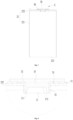
- Fig. 1 is a schematic structural diagram of a vehicle according to some embodiments of the present application.
- the box body 5 is used for accommodating the battery cell, and the box body 5 may be of various structures.
- the box body 5 may include a first box body portion 5a and a second box body portion 5b.
- the first box body portion 5a and the second box body portion 5b may be covered by each other.
- the first box body portion 5a and the second box body portion 5b together define an accommodating space 5c for accommodating the battery cell.
- the second box body portion 5b may be a hollow structure with one open side.
- the first box body portion 5a is a plate-shaped structure.
- the first box body portion 5a covers the open side of the second box body portion 5b, so that the box body 5 having the accommodating space 5c is formed.
- the electrode assembly 10 includes a first electrode plate, a second electrode plate, and a separator for separating the first electrode plate and the second electrode plate.
- the polarities of the first electrode plate and the second electrode plate are opposite.
- one of the first electrode plate and the second electrode plate is a positive electrode plate
- the other one of the first electrode plate and the second electrode plate is a negative electrode plate.
- the first electrode plate, the second electrode plate and the separator are all strip-shaped structures, and the first electrode plate, the second electrode plate and the separator are wound together to form a winding structure.
- the winding structure may be a cylinder structure, a flat structure, or a structure of other shapes.
- the electrode assembly 10 includes a main body portion 12, a first tab 11 and a second tab 13.
- the first tab 11 and the second tab 13 protrude from the main body portion 12.
- the first tab 11 is a portion of the first electrode plate that is not coated with the active material layer
- the second tab 13 is a portion of the second electrode plate that is not coated with the active material layer.
- one of the first tab 11 and the second tab 13 is a tab with positive polarity, and the other is a tab with negative polarity.
- the current collecting member 40 is abutted against the bottom surface 312 of the first recess.
- the bottom surface 312 of the first recess is not likely to be deformed during the shaping process of the electrode terminal 30, which can ensure that the close contact between the current collecting member 40 and the bottom surface 312 of the first recess, and improve the connection strength between the current collecting member 40 and the electrode terminal 30.
- the current collecting member 40 may be connected to the bottom surface 312 of the first recess by pressing, bonding, welding or other manners.
- the first recess 31 is provided at the end of the electrode terminal 30 that faces the first tab 11, and the side wall 311 of the first recess is bent outward so that the electrode terminal 30 is fixed to the wall of the casing 20.
- the squeezed part of the electrode terminal 30 is the side wall 311 of the first recess, and the side wall 311 of the first recess is a wall-shaped structure and is easy to be bent, so that the pressure to which the electrode terminal 30 is subjected during the shaping process can be reduced, stress concentration can be reduced, and mounting difficulty of the electrode terminal 30 can be reduced.
- the side wall 311 of the first recess is squeezed by the external device, so that the risk of the bottom surface 312 of the first recess being deformed during the bending of the side wall 311 of the first recess can be reduced, thereby ensuring the close contact of the current collecting member 40 with the bottom surface 312 of the first recess and improving the connection strength between the current collecting member 40 and the electrode terminal 30.
- the casing 20 includes a cover plate 23 and a casing body 22.
- the casing body 22 includes a casing side wall 221 and a casing bottom wall 222 that are integrally formed.
- the casing side wall 221 surrounds the casing bottom wall 222.
- One end of the casing side wall 221 is connected to the casing bottom wall 222, and the other end of the casing side wall 221 encircles to form an opening 223 opposite to the casing bottom wall 222.
- the cover plate 23 covers the opening 223.
- the wall is the casing bottom wall 222 or the cover plate 23.
- the casing body 22 is a hollow structure with an opening on one side.
- the cover plate 23 covers the opening of the casing body 22 and forms a sealing connection to form an accommodating cavity for accommodating the electrode assembly 10 and the electrolyte.
- the casing body 22 may be in various shapes, for example, a cylinder, a cuboid, and the like.
- the shape of the casing body 22 may be determined depending on the specific shape of the electrode assembly 10. For example, if the electrode assembly 10 is a cylinder structure, the casing body 22 may be selected to be a cylindrical casing body. If the electrode assembly 10 is a cuboid structure, the casing body 22 may be selected to be a cuboid casing body.
- the wall may be the casing bottom wall 222 or the cover plate 23, which is not limited in the embodiments.
- a surface of the electrode terminal 30 that faces away from the first tab 11 is a flat surface.
- the surface of the electrode terminal 30 that faces away from the first tab 11 is the end face of the end of the electrode terminal 30 that is away from the first tab 11, and the end face is exposed to the outside of the casing 20.
- the current collecting member 40 is configured to be abutted against the bottom surface 312 of the first recess, and the bottom surface 312 of the first recess is provided to be a flat surface, so that the current collecting member 40 can be in close contact with the bottom surface 312 of the first recess, which improves the connection strength and current flow allowance therebetween.
- the first tab 11 is wound in multiple turns around the central axis of the electrode assembly 10, in other words, the first tab 11 includes multiple turns of tab layers. After the winding is completed, the first tab 11 is generally cylindrical, and a gap is left between two adjacent tab layers.
- the first tab 11 may be processed to reduce the gap between the tab layers, so as to facilitate the connection between the first tab 11 and the current collecting member 40.
- the first tab 11 may be kneaded flat, to enable end regions of the first tab 11 that are away from the main body portion 12 to be gathered up and assembled together.
- the kneading process forms a dense end surface at an end of the first tab 11 away from the main body portion 12, reduces the gap between tab layers, and facilitates the connection of the first tab 11 with the current collecting member 40.
- a conductive material may be filled between two adjacent turns of tab layers, so as to reduce the gap between the tab layers.
- the second tab 13 is wound around the central axis of the electrode assembly 10 in multiple turns, and the second tab 13 includes multiple turns of tab layers.
- the second tab 13 is also kneaded flat to reduce the gap between the tab layers of the second tab 13.
- the battery cell 7 is a cylindrical battery cell.
- the electrode assembly 10 is a cylinder structure, and the casing side wall 221 is a round tube structure.
- the limiting portion 32 overlaps with the wall, and at least a portion of the folded edge structure 34 overlaps with the wall.
- the limiting portion 32 and the folded edge structure 34 may directly clamp the wall, or may indirectly clamp the wall through other components.
- the limiting portion 32 may be a plate-shaped structure, for example, the limiting portion 32 may be a flat plate structure, and the surface of the limiting portion 32 that faces away from the body portion 33 may be a flat surface.
- the body portion 33 may be a cylinder structure provided with the first recess 31, for example, the body portion 33 may be a cylinder structure.
- the body portion 33 may be inserted into the casing 20 from the outside of the casing 20, and the limiting portion 32 may limit the position of the electrode terminal 30 from the outside.
- the side wall 311 of the first recess is bent outward to form the folded edge structure 34.
- the folded edge structure 34 and the limiting portion 32 respectively clamp the wall from the two sides of the wall, so as to fix the electrode terminal 30 to the wall.
- the first recess 31 is a tapered recess whose cross-sectional area gradually increases along the direction away from the limiting portion 32.
- the tapered recess allows easier insertion of the first pressing block.
- the limiting portion 32 may have a relative large size in the radial direction, which facilitates the assembling of the limiting portion 32 and the external bus component, increases the connection area between the limiting portion 32 and the bus components, and improves the current flow allowance.
- the folded edge structure 34 has a relatively small size in the radial direction, so that the pressure required for the shaping of the folded edge structure 34 by bending can be reduced, and the difficulty of the shaping of the folded edge structure 34 by bending can be reduced.
- a thickness of at least a part of the folded edge structure 34 that extends from an outer end surface 341 of the folded edge structure 34 gradually increases from an outer side to an inner side of the folded edge structure 34.
- the entire folded edge structure 34 may be the thickness-varying region, that is, the entire thickness of the folded edge structure 34 tends to increase gradually from the outer side to the inner side of the folded edge structure 34.
- the thickness-varying region may be the thickness-varying region with the thickness-varying region surrounding the outside of other regions of the folded edge structure 34.
- the inner surface of the wall and the outer surface of the wall are disposed opposite to each other in the thickness direction Z, and the inner surface of the wall faces the first tab 11.
- the electrode lead-out hole 21 penetrates the wall, and the hole wall surface of the electrode lead-out hole 21 is connected to the inner surface of the wall and the outer surface of the wall.
- the bottom surface 312 of the first recess is closer to the first tab 11 than the inner surface of the wall, that is, the bottom surface 312 of the first recess is positioned outside the electrode lead-out hole 21.
- the bottom surface 312 of the first recess is closer to the first tab 11 than the inner surface of the wall, so as to reduce the pressure exerted on the wall by the side wall 311 of the first recess during the bending process, thereby reducing the risk that the wall is damaged by pressure.
- the sealing member 50 is provided to seal the electrode lead-out hole 21, which can improve the sealing performance of the battery cell 7, reduce the risk of electrolyte leakage, and improve the safety of the battery cell 7.
- the folded edge structure 34 is configured to limit the position of the electrode terminal 30 from the inside, so as to prevent the limiting portion 32 from being spread under the action of the elastic force by the first sealing portion 51.
- the portion of the first sealing portion 51 that corresponds to the folded edge structure 34 in the thickness direction Z is subjected to greater pressure.
- a first inner boundary line and a first outer boundary line are located where the first protrusion 35 and the limiting portion 32 are connected, and the first inner boundary line is located at an end of the first protrusion 35 that faces the body portion 33.
- a second external boundary is located where the body portion 33 and the limiting portion 32 are connected.
- the minimum distance between the first protrusion 35 and the body portion 33 in the radial direction is the minimum distance between the second outer boundary line and the first inner boundary line in the radial direction.
- the minimum distance between the first protrusion 35 and the body portion 33 in the radial direction is a difference between the inner radius of the first protrusion 35 and the outer radius of the end of the body portion 33 that is connected to the limiting portion 32.
- the minimum distance between the second protrusion and the outer edge of the limiting portion 32 in the radial direction is the minimum distance between the outer edge of the limiting portion 32 and the third outer boundary line in the radial direction.
- the minimum distance between the second protrusion and the outer edge of the limiting portion 32 in the radial direction is the difference between the outer radius of the limiting portion 32 and the outer radius of the second protrusion.
- the first protrusion 35 presses against the first sealing portion 51 and exerts a supporting force on the limiting portion 32.
- the minimum distance between the second protrusion and the body portion 33 is smaller than the minimum distance between the second protrusion and the outer edge of the limiting portion 32, which can reduce the torque received by the limiting portion 32, and reduce the risk of warping and deformation of the limiting portion 32.
- the sealing member 50 further includes a second sealing portion 52 sleeved on the body portion 33 and connected to the first sealing portion 51. A part of the second sealing portion 52, with squeeze by the folded edge structure 34, is bent outward and clamped between the wall and the folded edge structure 34.
- the second sealing portion 52 can not only improve the sealing performance, but also separate the body portion 33 from the wall, so as to avoid direct contact and friction between the body portion 33 and the wall, and reduce the risk of particle generation.
- the second sealing portion 52 can directly extend into the electrode lead-out hole 21 and be bent along with the formation of the folded edge structure 34, so that the sealing member 50 does not need to be integrated on the wall in advance, which can simplify the assembly process.
- the electrode assembly 10 further includes a second tab 13 having a polarity opposite to that of the first tab 11, and the second tab 13 is electrically connected to the wall.
- the sealing member 50 insulates and separates the wall from the electrode terminal 30.
- the wall and the electrode terminal 30 may have different polarities, that is, the electrode terminal 30 and the wall may serve as two output electrodes of the battery cell 7, respectively.
- the casing 20 itself may be used as the output electrode of the battery cell 7, thereby eliminating a conventional electrode terminal 30 and simplifying the structure of the battery cell 7.
- the wall is the negative output electrode of the battery cell 7
- the electrode terminal 30 is the positive output electrode of the battery cell 7.
- the wall is the positive output electrode of the battery cell 7, and the electrode terminal 30 is the negative output electrode of the battery cell 7.
- the sealing member 50 insulates and separates the wall from the electrode terminal 30, so that the wall and the electrode terminal 30 may have different polarities, and the wall and the electrode terminal 30 may serve as two output electrodes of the battery cell 7, which can simplify the structure of the battery cell 7, and ensure good current flow allowance of the battery cell 7.
- the wall and the electrode terminal 30 are positioned at a same end of the battery cell 7, so that the bus components can be assembled to the same side of the battery cell 7, which can simplify the assembly process and improve the efficiency of assembling a plurality of battery cells 7 into a group.
- the wall is the casing bottom wall 222.
- the first tab 11 is positioned at the end of the electrode assembly 10 that faces the casing bottom wall 222
- the second tab 13 is positioned at the end of the electrode assembly 10 that faces the cover plate 23.
- the cover plate 23 is connected to each of the second tab 13 and the casing side wall 221, so as to electrically connect the second tab 13 to the casing bottom wall 222.
- the second tab 13 is a negative electrode tab
- a base material of the cover plate 23 and a base material of the casing body 22 are both steel.
- the casing body 22 is electrically connected to the negative electrode tab, so that the casing body 22 is in a low potential state, and the steel casing body 22 is not likely to be corroded by the electrolyte in the low potential state, which reduces safety risks.
- the current collecting member 40 includes a first current collecting portion 41 and a second current collecting portion 42 connected to the first current collecting portion 41.
- the first current collecting portion 41 is configured to be connected to the first tab 11 to electrically connect the current collecting member 40 to the first tab 11.
- the second current collecting portion 42 is configured to be connected to the electrode terminal 30 to electrically connect the current collecting member 40 to the electrode terminal 30.
- the second current collecting portion 42 protrudes from a surface of the first current collecting portion 41 that faces the electrode terminal 30, to extend into the first recess 31 and abut against the bottom surface 312 of the first recess.
- the first current collecting portion 41 and the second current collecting portion 42 may be integrally formed.
- the first current collecting portion 41 and the second current collecting portion 42 may be discrete structures, that is, the first current collecting portion 41 and the second current collecting portion 42 are two components provided separately, and they are joined together by bonding, welding, snapping or other manners.
- the first current collecting portion 41 may be connected to the first tab 11 by welding, bonding or other manners.
- the first current collecting portion 41 is positioned between the wall and the first tab 11, and the first current collecting portion 41 may have a relatively large size to ensure an enough connection area between the first tab 11 and the current collecting member 40 and improve the current flow allowance.
- the second current collecting portion 42 may be connected to the bottom surface 312 of the first recess by welding, bonding, or other manners.
- the second current collecting portion 42 may be a non-hollow structure or a hollow structure.
- the first current collecting portion 41 may be connected to the first tab 11 to ensure a good connection strength and a good overcurrent capacity between the current collecting member 40 and the first tab 11.
- the second current collecting portion 42 protrudes from the first current collecting portion 41 and can extend into the first recess 31 and abut against the bottom surface 312 of the first recess, thereby ensuring a close contact between the current collecting member 40 and the bottom surface 312 of the first recess, which ensures a good current flow allowance and a good connection strength between the electrode terminal 30 and the current collecting member 40.
- the first current collecting portion 41 surrounds the outside of the second current collecting portion 42.
- a second recess 43 is formed at a position of the current collecting member 40 that corresponds to the second current collecting portion 42, and the second recess 43 is recessed from a surface of the first current collecting portion 41 that faces the first tab 11 along a direction away from the first tab 11.
- the second recess 43 is provided, so that the strength of the second current collecting portion 42 can be reduced, and the elastic deformation capability of the second current collecting portion 42 can be improved.
- the second current collecting portion 42 can release the stress through elastic deformation, reduce the stress transferred to the first tab 11, and reduce the risk of first tab 11 being damaged by pressure.
- the second current collecting portion 42 can further serve as a buffer though elastic deformation, thereby reducing the risk of the first tab 11 being damaged by pressure.
- the second recess 43 is provided, so that the weight of the current collecting member 40 can be reduced, and the energy density of the battery cell 7 can be improved.
- the first current collecting portion 41 and the second current collecting portion 42 are formed as an integrated structure, so that the process for connecting the first current collecting portion 41 to the second current collecting portion 42 can be omitted, and the resistance therebetween can be reduced.
- the current collecting member 40 is fabricated by stamping metal plate.
- the metal plate forms the second recess 43 and the second current collecting portion 42 at stamped positions.
- the first current collecting portion 41 is spaced apart from the electrode terminal 30.
- the second current collecting portion 42 In the assembling of the electrode terminal 30 and the current collecting member 40, the second current collecting portion 42 needs to press against the bottom surface 312 of the first recess. If the first current collecting portion 41 is also in contact with the electrode terminal 30, over-positioning occurs between the electrode terminal 30 and the current collecting member 40, and it is difficult to ensure that the second current collecting portion 42 is in close contact with the bottom surface 312 of the first recess. In this embodiment, the first current collecting portion 41 is spaced apart from the electrode terminal 30 to prevent the first current collecting portion 41 from interfering with the second current collecting portion 42 being abutted against the bottom surface 312 of the first recess, so that a good connection strength between the current collecting member 40 and the electrode terminal 30 is ensured.
- the first current collecting portion 41 is abutted against and welded to the first tab 11, and the second current collecting portion 42 is abutted against and welded to the bottom surface 312 of the first recess.
- the welding can reduce the contact resistance between the first current collecting portion 41 and the first tab 11 and the contact resistance between the second current collecting portion 42 and the electrode terminal 30, thereby improving the current flow allowance.
- the first current collecting portion 41 and the first tab 11 may be connected by laser welding, and the second current collecting portion 42 and the bottom surface 312 of the first recess may be connected by resistance welding.
- the electrode assembly 10 includes a winding center hole 14, the winding center hole 14 is configured to be positioned corresponding to the second current collecting portion 42, and the winding center hole is configured to be penetrated by an external welding part to weld the second current collecting portion 42 to the bottom surface 312 of the first recess.
- the electrode assembly 10 is made by winding the first electrode plate, the second electrode plate and the separator on a winding tool. After the electrode assembly 10 is shaped by winding, the winding tool is pulled out from the electrode assembly 10. After the winding tool is pulled out, a winding center hole 14 is formed in the middle of the electrode assembly 10.
- the winding center hole 14 penetrates the first tab 11, the main body portion 12, and the second tab 13 along the axial direction of the electrode assembly 10.
- the winding center hole 14 can provide a clearance space for the external welding part, so that the external welding part can pass through the electrode assembly 10 and weld the second current collecting portion 42 to the bottom surface 312 of the first recess.
- conductive glue is provided in the first recess 31.
- the conductive glue connects the second current collecting portion 42 to the electrode terminal 30 to realize an electrical connection between the current collecting member 40 and the electrode terminal 30.
- the first recess 31 may be filled with the conductive glue in advance, and after the second current collecting portion 42 extends into the first recess 31, the second current collecting portion 42 squeezes the conductive glue, and the conductive glue connects the second current collecting portion 42 to the electrode terminal 30.
- the second current collecting portion 42 and the electrode terminal 30 are connected by the conductive glue, instead of welding the second current collecting portion 42 to the electrode terminal 30, so that the difficulty for connecting the second current collecting portion 42 to the electrode terminal 30 can be lowered.
- the battery cell 7 further includes an insulating sheet 60 surrounding an outside of the second current collecting portion 42 and at least partially clamped between the first current collecting portion 41 and the electrode terminal 30.
- the insulating sheet 60 clamped between the first current collecting portion 41 and the electrode terminal 30 is provided, so that the first recess 31 can be sealed, and the risk of material leakage from the first recess 31 can be reduced.
- the insulating sheet 60 can seal at least a part of the particles generated by welding in the first recess 31, so that the risk of particles falling into the electrode assembly 10 is reduced and the potential safety hazard is reduced.
- the insulating sheet 60 can seal the conductive glue in the first recess 31, so that the risk of leakage of the conductive glue into the electrode assembly 10 is reduced and the potential safety hazard is reduced.
- the insulating sheet 60 is elastic and is configured to be elastically deformed when squeezed by the first current collecting portion 41 and the electrode terminal 30.
- the electrode terminal 30 squeezes the insulating sheet 60, and the insulating sheet 60 can be elastically deformed to prevent the insulating sheet 60 from interfering with the second current collecting portion 42 being abutted against the bottom surface 312 of the first recess, which ensures a good connection strength between the current collecting member 40 and the electrode terminal 30.
- Fig. 9 is a partial cross-sectional schematic diagram of a battery cell according to some other embodiments of the present application.
- the second current collecting portion 42 is a non-hollow structure.
- the second current collecting portion 42 is provided as a non-hollow structure, which can improve the overcurrent capacity of the second current collecting portion 42.
- the second current collecting portion 42 can be welded to the electrode terminal 30 by means of resistance welding.
- the second current collecting portion 42 of the non-hollow structure generates more heat, which facilitates the welding of the second current collecting portion 42 to the electrode terminal 30, and reduces the difficulty of welding the second current collecting portion 42 to the electrode terminal 30.
- the first current collecting portion 41 and the second current collecting portion 42 may be integrally formed, for example, a solid second current collecting portion 42 may be milled on a metal plate.
- the first current collecting portion 41 and the second current collecting portion 42 are independent structures from each otherand are connected by welding.
- the process of welding the first current collecting portion 41 to the second current collecting portion 42 is simple, which helps to save materials and reduce costs.
- a part of the material of the metal plate needs to be removed by milling, which will cause material waste.
- a larger metal plate is directly welded to a smaller metal block and no material needs to be removed, which can save materials and reduce costs.
- Fig. 10 is a partial cross-sectional schematic diagram of a battery cell according to yet some other embodiments of the present application.
- the sealing member 50 further includes a second protrusion 53 protruding from a surface of the first sealing portion 51 that faces the limiting portion 32 and surrounding the body portion 33.
- the second protrusion 53 is configured to press against the limiting portion 32 to seal the electrode lead-out hole 21.
- the second protrusion 53 protrudes from the first sealing portion 51.
- the limiting portion 32 and the wall clamp the first sealing portion 51 the limiting portion 32 compresses both of the second protrusion 53 and the first sealing portion 51, thereby increasing the compression of the sealing member 50 at the second protrusion 53 and improves the sealing performance.
- the projection of the second protrusion 53 along the thickness direction Z of the wall is within the projection of the folded edge structure 34 along the thickness direction Z.
- the projection of the second protrusion 53 along the thickness direction Z of the wall is within the projection of the folded edge structure 34 along the thickness direction Z, so that the second protrusion and the first sealing portion 51 can be clamped by the limiting portion 32 and the folded edge structure 34 from both sides, which increases the compression of the sealing member 50 at the second protrusion and improves the sealing performance.
- the minimum distance between the second protrusion 53 and the body portion 33 is smaller than the minimum distance between the second protrusion 53 and the outer edge of the limiting portion 32.
- the minimum distance between the second protrusion 53 and the body portion 33 is smaller than the minimum distance between the second protrusion 53 and the outer edge of the limiting portion 32, which can reduce the torque received by the limiting portion 32, and reduce the risk of warping and deformation of the limiting portion 32.
- Fig. 11 is a schematic flowchart of a method for assembling a casing body and an electrode terminal according to some embodiments of the present application.
- the method for assembling the case and the electrode terminal according to an embodiment of the present application includes:
- the first recess is provided at the end of the electrode terminal, and the side wall of the first recess is bent outward so that the electrode terminal is fixed to the casing bottom wall.
- the squeezed part of the electrode terminal is the side wall of the first recess, and the side wall of the first recess is a wall-shaped structure and is easy to be bent, so that the pressure to which the electrode terminal is subjected during the shaping process can be reduced, stress concentration can be reduced, and mounting difficulty of the electrode terminal can be reduced.
- the side wall of the first recess is squeezed by the external device, so that the risk of the bottom surface of the first recess being deformed during the bending of the side wall of the first recess can be reduced.
- the "bending the side wall of the first recess outward" in step S130 includes: making a first pressing block extend into the first recess and spreading the side wall of the first recess, to make the side wall of the first recess tilt outward; squeezing the side wall of the first recess by a second pressing block, to make the side wall of the first recess bend toward the casing bottom wall.
- the bending direction of the side wall of the first recess is uncertain, and the side wall of the first recess may bend inwardly relative to the first recess.
- the side wall of the first recess is gradually spread, so that the side wall of the first recess is inclined outward.
- the second pressing block can more easily press against the inner wall surface of the side wall of the first recess, so that the side wall of the first recess can be bent along a preset direction.
- steps S 110 and S 120 are in no particular order, and may also be performed simultaneously.
- Fig. 12 is a schematic block diagram of an assembly apparatus including a casing body and an electrode terminal according to some embodiments of the present application.
- the side wall of the first recess is gradually spread, so that the side wall of the first recess is inclined outward.
- the second pressing block 832 can more easily press against the inner wall surface of the side wall of the first recess, so that the side wall of the first recess can be bent along a preset direction.
- Fig. 13 is a schematic flowchart of a method for manufacturing a battery cell according to some embodiments of the present application.
- the method for manufacturing the battery cell according to the embodiments of the present application includes:
- the winding center hole can provide a clearance space for the external welding part, so that the external welding part can pass through the electrode assembly and weld the current collecting member to the bottom surface of the first recess.
- steps S210 and S220 are in no particular order, and may also be performed simultaneously.
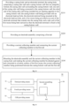
- Fig. 14 is a schematic block diagram of a system for manufacturing a battery cell according to some embodiments of the present application.
- the system 90 for manufacturing the battery cell according to the embodiments of the present application includes:
- the electrode assembly including a winding center hole.
- the second assembly part 94 includes a welding part 941 configured to enter the casing body from the opening and pass through the winding center hole to weld the current collecting member to the bottom surface of the first recess.
- the winding center hole can provide a clearance space for the welding part 941, so that the welding part 941 can pass through the electrode assembly and weld the current collecting member to the bottom surface of the first recess.
Landscapes
- Chemical & Material Sciences (AREA)
- Chemical Kinetics & Catalysis (AREA)
- Electrochemistry (AREA)
- General Chemical & Material Sciences (AREA)
- Engineering & Computer Science (AREA)
- Manufacturing & Machinery (AREA)
- Connection Of Batteries Or Terminals (AREA)
Priority Applications (1)
| Application Number | Priority Date | Filing Date | Title |
|---|---|---|---|
| EP24215115.7A EP4489190A3 (de) | 2021-10-20 | 2021-10-20 | Batteriezelle und herstellungsverfahren und system dafür, batterie und elektrische vorrichtung |
Applications Claiming Priority (3)
| Application Number | Priority Date | Filing Date | Title |
|---|---|---|---|
| EP21876742.4A EP4199207B1 (de) | 2021-10-20 | 2021-10-20 | Batteriezelle, verfahren und system zur herstellung einer batteriezelle, batterie und elektrische vorrichtung |
| EP24215115.7A EP4489190A3 (de) | 2021-10-20 | 2021-10-20 | Batteriezelle und herstellungsverfahren und system dafür, batterie und elektrische vorrichtung |
| PCT/CN2021/125077 WO2023065173A1 (zh) | 2021-10-20 | 2021-10-20 | 电池单体及其制造方法和制造系统、电池以及用电装置 |
Related Parent Applications (2)
| Application Number | Title | Priority Date | Filing Date |
|---|---|---|---|
| EP21876742.4A Division-Into EP4199207B1 (de) | 2021-10-20 | 2021-10-20 | Batteriezelle, verfahren und system zur herstellung einer batteriezelle, batterie und elektrische vorrichtung |
| EP21876742.4A Division EP4199207B1 (de) | 2021-10-20 | 2021-10-20 | Batteriezelle, verfahren und system zur herstellung einer batteriezelle, batterie und elektrische vorrichtung |
Publications (2)
| Publication Number | Publication Date |
|---|---|
| EP4489190A2 true EP4489190A2 (de) | 2025-01-08 |
| EP4489190A3 EP4489190A3 (de) | 2025-06-18 |
Family
ID=85982715
Family Applications (2)
| Application Number | Title | Priority Date | Filing Date |
|---|---|---|---|
| EP21876742.4A Active EP4199207B1 (de) | 2021-10-20 | 2021-10-20 | Batteriezelle, verfahren und system zur herstellung einer batteriezelle, batterie und elektrische vorrichtung |
| EP24215115.7A Pending EP4489190A3 (de) | 2021-10-20 | 2021-10-20 | Batteriezelle und herstellungsverfahren und system dafür, batterie und elektrische vorrichtung |
Family Applications Before (1)
| Application Number | Title | Priority Date | Filing Date |
|---|---|---|---|
| EP21876742.4A Active EP4199207B1 (de) | 2021-10-20 | 2021-10-20 | Batteriezelle, verfahren und system zur herstellung einer batteriezelle, batterie und elektrische vorrichtung |
Country Status (4)
| Country | Link |
|---|---|
| US (1) | US20230118437A1 (de) |
| EP (2) | EP4199207B1 (de) |
| CN (1) | CN116670897B (de) |
| WO (1) | WO2023065173A1 (de) |
Families Citing this family (6)
| Publication number | Priority date | Publication date | Assignee | Title |
|---|---|---|---|---|
| CN118198665A (zh) * | 2023-04-28 | 2024-06-14 | 宁德时代新能源科技股份有限公司 | 电池单体、电池及用电装置 |
| KR102853427B1 (ko) * | 2023-06-09 | 2025-09-02 | 삼성에스디아이 주식회사 | 이차전지 |
| CN116682935A (zh) * | 2023-08-04 | 2023-09-01 | 宁德时代新能源科技股份有限公司 | 电池单体、电池及用电装置 |
| CN119725912A (zh) * | 2023-09-26 | 2025-03-28 | 宁德时代新能源科技股份有限公司 | 电池单体、电池及用电装置 |
| CN222380700U (zh) * | 2024-04-22 | 2025-01-21 | 株式会社Aesc日本 | 二次电池、电池组及电子装置 |
| CN121663084A (zh) * | 2026-02-04 | 2026-03-13 | 中创新航技术研究中心(深圳)有限公司 | 电池模组、电池装置和用电装置 |
Family Cites Families (20)
| Publication number | Priority date | Publication date | Assignee | Title |
|---|---|---|---|---|
| US6673489B2 (en) * | 2001-12-28 | 2004-01-06 | Quallion Llc | Electric battery assembly and method of manufacture |
| FR2905525B1 (fr) * | 2006-09-05 | 2008-10-31 | Accumulateurs Fixes | Dispositif de raccordement electrique pour borne de sortie d'un accumulateur de courant |
| JP5606947B2 (ja) * | 2010-03-18 | 2014-10-15 | 三洋電機株式会社 | 円筒型二次電池およびその製造方法 |
| WO2012169055A1 (ja) * | 2011-06-10 | 2012-12-13 | 日立ビークルエナジー株式会社 | 二次電池 |
| JP5871871B2 (ja) * | 2013-09-12 | 2016-03-01 | 日立オートモティブシステムズ株式会社 | 角形二次電池 |
| JP6731176B2 (ja) * | 2016-01-21 | 2020-07-29 | 株式会社Gsユアサ | 蓄電素子、及び蓄電素子の製造方法 |
| KR102663722B1 (ko) * | 2016-09-05 | 2024-05-07 | 삼성에스디아이 주식회사 | 이차 전지 |
| JP6528976B2 (ja) * | 2016-11-08 | 2019-06-12 | トヨタ自動車株式会社 | 組電池 |
| JP2018139190A (ja) * | 2017-02-24 | 2018-09-06 | リチウム エナジー アンド パワー ゲゼルシャフト ミット ベシュレンクテル ハフッング ウント コンパニー コマンディトゲゼルシャフトLithium Energy and Power GmbH & Co. KG | 蓄電素子 |
| JPWO2019131481A1 (ja) * | 2017-12-27 | 2021-01-21 | 株式会社Gsユアサ | 蓄電素子 |
| CN207800665U (zh) * | 2018-02-01 | 2018-08-31 | 宁德时代新能源科技股份有限公司 | 二次电池的顶盖组件以及二次电池 |
| CN108428921A (zh) * | 2018-02-01 | 2018-08-21 | 宁德时代新能源科技股份有限公司 | 二次电池 |
| CN111162205B (zh) * | 2018-11-07 | 2024-10-18 | 宁德时代新能源科技股份有限公司 | 二次电池以及二次电池的制造方法 |
| CN209401756U (zh) * | 2018-12-29 | 2019-09-17 | 宁德时代新能源科技股份有限公司 | 二次电池和电池模组 |
| CN111987340B (zh) * | 2019-05-24 | 2024-10-15 | 宁德时代新能源科技股份有限公司 | 电池单元及其制造方法、电池模组 |
| CN210006769U (zh) * | 2019-07-09 | 2020-01-31 | 宁德时代新能源科技股份有限公司 | 顶盖组件以及二次电池 |
| CN110429214B (zh) * | 2019-08-07 | 2021-12-07 | 宁德时代新能源科技股份有限公司 | 二次电池的盖组件及二次电池 |
| CN111900275A (zh) * | 2020-08-04 | 2020-11-06 | 珠海冠宇电池股份有限公司 | 扣式电池及其制备方法 |
| CN113346201A (zh) * | 2021-05-21 | 2021-09-03 | 湖北亿纬动力有限公司 | 圆柱型电池、电池模组和电池包 |
| CN216251022U (zh) * | 2021-10-20 | 2022-04-08 | 宁德时代新能源科技股份有限公司 | 电池单体、电池以及用电装置 |
-
2021
- 2021-10-20 CN CN202180087229.1A patent/CN116670897B/zh active Active
- 2021-10-20 EP EP21876742.4A patent/EP4199207B1/de active Active
- 2021-10-20 EP EP24215115.7A patent/EP4489190A3/de active Pending
- 2021-10-20 WO PCT/CN2021/125077 patent/WO2023065173A1/zh not_active Ceased
-
2022
- 2022-04-15 US US17/721,387 patent/US20230118437A1/en active Pending
Also Published As
| Publication number | Publication date |
|---|---|
| CN116670897A (zh) | 2023-08-29 |
| WO2023065173A1 (zh) | 2023-04-27 |
| US20230118437A1 (en) | 2023-04-20 |
| EP4199207B1 (de) | 2025-01-29 |
| EP4199207A1 (de) | 2023-06-21 |
| EP4489190A3 (de) | 2025-06-18 |
| EP4199207A4 (de) | 2023-06-21 |
| CN116670897B (zh) | 2025-07-29 |
Similar Documents
| Publication | Publication Date | Title |
|---|---|---|
| EP4199207B1 (de) | Batteriezelle, verfahren und system zur herstellung einer batteriezelle, batterie und elektrische vorrichtung | |
| EP4266481A1 (de) | Batteriezelle, batterie und elektrische vorrichtung | |
| CN216085065U (zh) | 电池单体、电池以及用电装置 | |
| EP4354576A1 (de) | Batteriezelle und herstellungsverfahren und system dafür, batterie und elektrische vorrichtung | |
| CN216251022U (zh) | 电池单体、电池以及用电装置 | |
| EP4120465B1 (de) | Batteriezelle, batterie und energieverbrauchsvorrichtung | |
| EP4181279B1 (de) | Batteriezelle, verfahren und system zur herstellung davon, batterie und elektrische vorrichtung | |
| EP4184669B1 (de) | Bodenzelle und herstellungsverfahren und herstellungssystem dafür, batterie und stromverbrauchende vorrichtung | |
| CN116711150A (zh) | 电池单体及其制造方法和制造设备、电池以及用电设备 | |
| EP4170781B1 (de) | Batteriezelle, verfahren und system zur herstellung einer batteriezelle, batterie und elektrische vorrichtung | |
| CN221632621U (zh) | 电池单体、电池及用电装置 | |
| CN218997009U (zh) | 电池单体、电池以及用电装置 | |
| CN217158363U (zh) | 电池单体、电池以及用电装置 | |
| US20240162579A1 (en) | Battery cell, method and system for manufacturing battery cell, battery and electrical apparatus | |
| EP4507083A1 (de) | Batteriezelle und herstellungsverfahren dafür sowie batterie und elektrische vorrichtung | |
| CN115349195B (zh) | 电池单体及其制造方法和制造系统、电池以及用电设备 | |
| EP4354556A1 (de) | Stromsammelkomponente, batteriezelle, batterie und elektrische vorrichtung | |
| EP4391166A1 (de) | Batteriezelle, batterie, stromverbrauchende vorrichtung sowie verfahren und vorrichtung zur herstellung einer batteriezelle | |
| KR102955181B1 (ko) | 전지 셀 및 그의 제조 방법, 제조 시스템, 전지 및 전기 장치 | |
| KR20260055527A (ko) | 전지 셀 및 그의 제조 방법, 제조 시스템, 전지 및 전기 장치 | |
| CN116093533A (zh) | 电池单体、电池、用电装置及电池单体的制造设备和方法 |
Legal Events
| Date | Code | Title | Description |
|---|---|---|---|
| PUAI | Public reference made under article 153(3) epc to a published international application that has entered the european phase |
Free format text: ORIGINAL CODE: 0009012 |
|
| STAA | Information on the status of an ep patent application or granted ep patent |
Free format text: STATUS: THE APPLICATION HAS BEEN PUBLISHED |
|
| AC | Divisional application: reference to earlier application |
Ref document number: 4199207 Country of ref document: EP Kind code of ref document: P |
|
| AK | Designated contracting states |
Kind code of ref document: A2 Designated state(s): AL AT BE BG CH CY CZ DE DK EE ES FI FR GB GR HR HU IE IS IT LI LT LU LV MC MK MT NL NO PL PT RO RS SE SI SK SM TR |
|
| REG | Reference to a national code |
Ref country code: DE Ref legal event code: R079 Free format text: PREVIOUS MAIN CLASS: H01M0050179000 Ipc: H01M0050188000 |
|
| RIC1 | Information provided on ipc code assigned before grant |
Ipc: H01M 50/559 20210101ALI20250224BHEP Ipc: H01M 50/107 20210101ALI20250224BHEP Ipc: H01M 50/548 20210101ALI20250224BHEP Ipc: H01M 50/567 20210101ALI20250224BHEP Ipc: H01M 50/533 20210101ALI20250224BHEP Ipc: H01M 50/528 20210101ALI20250224BHEP Ipc: H01M 50/179 20210101ALI20250224BHEP Ipc: H01M 50/176 20210101ALI20250224BHEP Ipc: H01M 50/184 20210101ALI20250224BHEP Ipc: H01M 50/188 20210101AFI20250224BHEP |
|
| PUAL | Search report despatched |
Free format text: ORIGINAL CODE: 0009013 |
|
| AK | Designated contracting states |
Kind code of ref document: A3 Designated state(s): AL AT BE BG CH CY CZ DE DK EE ES FI FR GB GR HR HU IE IS IT LI LT LU LV MC MK MT NL NO PL PT RO RS SE SI SK SM TR |
|
| RIC1 | Information provided on ipc code assigned before grant |
Ipc: H01M 50/559 20210101ALI20250513BHEP Ipc: H01M 50/107 20210101ALI20250513BHEP Ipc: H01M 50/548 20210101ALI20250513BHEP Ipc: H01M 50/567 20210101ALI20250513BHEP Ipc: H01M 50/533 20210101ALI20250513BHEP Ipc: H01M 50/528 20210101ALI20250513BHEP Ipc: H01M 50/179 20210101ALI20250513BHEP Ipc: H01M 50/176 20210101ALI20250513BHEP Ipc: H01M 50/184 20210101ALI20250513BHEP Ipc: H01M 50/188 20210101AFI20250513BHEP |
|
| STAA | Information on the status of an ep patent application or granted ep patent |
Free format text: STATUS: REQUEST FOR EXAMINATION WAS MADE |
|
| 17P | Request for examination filed |
Effective date: 20251205 |
|
| GRAP | Despatch of communication of intention to grant a patent |
Free format text: ORIGINAL CODE: EPIDOSNIGR1 |
|
| STAA | Information on the status of an ep patent application or granted ep patent |
Free format text: STATUS: GRANT OF PATENT IS INTENDED |