EP4491004A1 - Tondeuse à gazon motorisée et utilisation de boîtier de tondeuse - Google Patents
Tondeuse à gazon motorisée et utilisation de boîtier de tondeuse Download PDFInfo
- Publication number
- EP4491004A1 EP4491004A1 EP23185078.5A EP23185078A EP4491004A1 EP 4491004 A1 EP4491004 A1 EP 4491004A1 EP 23185078 A EP23185078 A EP 23185078A EP 4491004 A1 EP4491004 A1 EP 4491004A1
- Authority
- EP
- European Patent Office
- Prior art keywords
- mower
- motor
- drive
- housing
- lawn mower
- Prior art date
- Legal status (The legal status is an assumption and is not a legal conclusion. Google has not performed a legal analysis and makes no representation as to the accuracy of the status listed.)
- Pending
Links
Images


Classifications
-
- A—HUMAN NECESSITIES
- A01—AGRICULTURE; FORESTRY; ANIMAL HUSBANDRY; HUNTING; TRAPPING; FISHING
- A01D—HARVESTING; MOWING
- A01D34/00—Mowers; Mowing apparatus of harvesters
- A01D34/01—Mowers; Mowing apparatus of harvesters characterised by features relating to the type of cutting apparatus
- A01D34/412—Mowers; Mowing apparatus of harvesters characterised by features relating to the type of cutting apparatus having rotating cutters
- A01D34/63—Mowers; Mowing apparatus of harvesters characterised by features relating to the type of cutting apparatus having rotating cutters having cutters rotating about a vertical axis
- A01D34/67—Mowers; Mowing apparatus of harvesters characterised by features relating to the type of cutting apparatus having rotating cutters having cutters rotating about a vertical axis hand-guided by a walking operator
- A01D34/68—Mowers; Mowing apparatus of harvesters characterised by features relating to the type of cutting apparatus having rotating cutters having cutters rotating about a vertical axis hand-guided by a walking operator with motor driven cutters or wheels
-
- A—HUMAN NECESSITIES
- A01—AGRICULTURE; FORESTRY; ANIMAL HUSBANDRY; HUNTING; TRAPPING; FISHING
- A01D—HARVESTING; MOWING
- A01D34/00—Mowers; Mowing apparatus of harvesters
- A01D34/01—Mowers; Mowing apparatus of harvesters characterised by features relating to the type of cutting apparatus
- A01D34/412—Mowers; Mowing apparatus of harvesters characterised by features relating to the type of cutting apparatus having rotating cutters
- A01D34/63—Mowers; Mowing apparatus of harvesters characterised by features relating to the type of cutting apparatus having rotating cutters having cutters rotating about a vertical axis
- A01D34/76—Driving mechanisms for the cutters
- A01D34/78—Driving mechanisms for the cutters electric
-
- A—HUMAN NECESSITIES
- A01—AGRICULTURE; FORESTRY; ANIMAL HUSBANDRY; HUNTING; TRAPPING; FISHING
- A01D—HARVESTING; MOWING
- A01D34/00—Mowers; Mowing apparatus of harvesters
- A01D34/01—Mowers; Mowing apparatus of harvesters characterised by features relating to the type of cutting apparatus
- A01D34/412—Mowers; Mowing apparatus of harvesters characterised by features relating to the type of cutting apparatus having rotating cutters
- A01D34/63—Mowers; Mowing apparatus of harvesters characterised by features relating to the type of cutting apparatus having rotating cutters having cutters rotating about a vertical axis
- A01D34/81—Casings; Housings
-
- A—HUMAN NECESSITIES
- A01—AGRICULTURE; FORESTRY; ANIMAL HUSBANDRY; HUNTING; TRAPPING; FISHING
- A01D—HARVESTING; MOWING
- A01D2101/00—Lawn-mowers
-
- A—HUMAN NECESSITIES
- A01—AGRICULTURE; FORESTRY; ANIMAL HUSBANDRY; HUNTING; TRAPPING; FISHING
- A01D—HARVESTING; MOWING
- A01D34/00—Mowers; Mowing apparatus of harvesters
- A01D34/01—Mowers; Mowing apparatus of harvesters characterised by features relating to the type of cutting apparatus
- A01D34/412—Mowers; Mowing apparatus of harvesters characterised by features relating to the type of cutting apparatus having rotating cutters
- A01D34/63—Mowers; Mowing apparatus of harvesters characterised by features relating to the type of cutting apparatus having rotating cutters having cutters rotating about a vertical axis
- A01D34/71—Mowers; Mowing apparatus of harvesters characterised by features relating to the type of cutting apparatus having rotating cutters having cutters rotating about a vertical axis with means for discharging mown material
Definitions
- the invention relates to a motor-driven lawn mower with a drive motor, a movable cutting tool that can be driven by the drive motor, a mower housing with a hood-shaped mowing deck that is open on one mowing side and within which the cutting tool is arranged, wherein the mower housing is designed for use with a motor-driven lawn mower with an internal combustion engine as the drive motor, in that a belt space is provided in the mower housing outside the mowing deck, which is designed to accommodate a drive belt connected to a drive shaft of the internal combustion engine.
- the invention further relates to the use of a mower housing for a lawn mower.
- the mowing deck and thus the lawn mower as a whole faces the area to be mowed, such as a lawn, during operation, i.e. the open mowing side usually points downwards when the mower is in operation.
- the hood shape of the mowing deck channels the mown grass clippings, for which it usually forms an associated mowing channel, and in particular prevents them from penetrating upwards into the mower housing or being thrown outwards at high speed to the side due to the rapid cutting movement of the cutting tool, usually a rotational movement.
- Motor-driven lawn mowers of this type in which an internal combustion engine is used as the drive motor, are known in various designs and are offered on the market by the applicant.
- a self-propelled type of such lawn mower i.e. one with a motor drive
- the drive motor not only as a drive for the cutting tool but also as a drive for one or more wheels of the mower and to couple a rear-wheel or front-wheel wheel drive unit or wheel drive transmission unit to the drive shaft of the internal combustion engine via a drive belt, such as a V-belt.
- the drive belt is accommodated in a belt space which is
- the mower housing has a hood-shaped mowing deck on its underside in which the cutting tool is arranged.
- the belt compartment is formed outside the mowing deck, ie separated from the mowing side of the mowing deck that is open to the outside or bottom, which prevents excessive contamination of the belt compartment or the drive belt.
- the invention is based on the technical problem of providing a motor-driven lawn mower of the type mentioned at the outset, which is further improved compared to the above-mentioned prior art and in particular enables advantageous multiple use or use of identical parts of a mower component for different lawn mower designs, and a use of an associated mower housing.
- the invention solves this problem by providing a motor-driven lawn mower with the features of claim 1 and using a mower housing with the features of claim 10.
- Advantageous further developments of the invention are the subject of the subclaims, the wording of which is hereby made part of the description by reference. This includes in particular all Embodiments of the invention which result from the combinations of features defined by the references in the subclaims.
- the lawn mower has an electric motor as the drive motor, and a cooling air duct with an air inlet, an air outlet and an air duct path from the air inlet to the air outlet is formed in the mower housing, wherein a fan drivable by the electric motor is arranged in the air duct path and the belt space is designed to form part of the air duct path.
- the belt space therefore fulfills an air guidance function as part of the air guidance path of a cooling air guide, whereby the cooling air can serve in particular to cool the electric motor, which functions as the drive motor for the cutting tool.
- electronic components e.g. for the mowing motor and/or a drive, can also be accommodated in the area around which the cooling air flows.
- the mower housing can also be used for a lawn mower not according to the invention, which has an internal combustion engine as the drive motor for the cutting tool and in which the belt space serves to accommodate a drive belt, with which, for example, a wheel drive unit or wheel drive gear unit for the purpose of motor-driven one or more wheels of the lawn mower or another component of the mower to be motor-driven is coupled to the drive shaft of the internal combustion engine, i.e. connected to this drive shaft.
- the belt space of the mower housing serves as usual to accommodate the drive belt for the wheel drive or for another drive; in designs of the lawn mower with an electric motor according to the invention, the belt space serves as part of the air guide path of the cooling air guide, with which cooling air can be guided in particular over the electric motor or components of the same that are to be cooled.
- the mower housing with the belt space formed in it can therefore be used completely or at least essentially unchanged, i.e. structurally identical, for lawn mower models with an internal combustion engine or with an electric motor, regardless of whether the lawn mower in question is equipped with the internal combustion engine or the electric motor as the drive motor. This represents an advantageous use of identical parts for the mower housing.
- the cooling air can be guided through it outside the mower deck. This avoids a connection of the air duct with the space enclosed by the hood-shaped mower deck, in which the cutting tool is located and in which the mown grass clippings are generated during active mower operation.
- Such a connection of the air duct for the cooling air with this active mowing space enclosed by the hood-shaped mower deck, also known as the mowing channel, is generally undesirable due to the susceptibility to dirt and the air pressure conditions during active operation of the typically rotating cutting tool.
- the belt space extends from a drive shaft area of the mower housing to a wheel drive area of the mower housing.
- the belt space can thus serve in particular to accommodate a drive belt for driving one or more wheels, such as the rear wheels or the front wheels, of the lawn mower when the lawn mower is equipped with the combustion engine, while in the case of the lawn mower equipped with the electric motor, the belt space advantageously enables cooling air to be guided from the area of the drive shaft of the electric motor in the mower housing to the wheel drive area of the mower housing.
- discharging the cooling air or alternatively sucking in the cooling air in this wheel drive area of the mower housing is advantageous in terms of guiding the cooling air.
- one or more components located there such as a wheel drive gear or a separate electric wheel drive motor, can be cooled by the cooling air in the wheel drive area.
- the belt space can extend from the drive shaft area of the mower housing to another area of the mower housing if the lawn mower is equipped with the combustion engine.
- the belt space extends essentially parallel to a plane of rotation of the cutting tool. Accordingly, in this case the cooling air in the belt space is also guided essentially parallel to the plane of rotation of the cutting tool, i.e. perpendicular to the axis of rotation of the cutting tool and thus generally also essentially perpendicular to the drive shaft of the electric motor.
- the cooling air can therefore be guided, for example, over the electric motor and then through the belt space away from the area of the electric motor or its drive shaft radially outwards.
- the belt space extends at a noticeable angle inclined to the plane of rotation of the cutting tool, or a non-rotationally driven cutting tool is used.
- the belt space extends adjacent to a hood roof side of the mower deck. This allows the cooling air to be guided through the belt space directly above the mower deck and separated from its hood-shaped, outwardly open mowing side in the mower housing.
- the belt space extends with, for example, a vertical distance from the mower deck or from its hood roof side.
- the air inlet and the air outlet are located outside the mowing deck.
- This design has the advantage that neither the air inlet nor the air outlet open into the open mowing side bordered by the mowing deck in a hat shape. This facilitates the guidance of the cooling air independently of the mown grass and the air pressure conditions on the open mowing side of the mowing deck during active mowing operation.
- the air inlet and/or the air outlet can be located on the mowing deck if this is useful for the corresponding applications.
- the air inlet is located in an upper area of the mower housing.
- This design is advantageous for many applications, since in this case the air inlet is located relatively far away from the lower area of the mower housing, which is more susceptible to dirt, i.e. relatively far away from the mowing deck and the mowing area it defines.
- the air inlet is arranged in a different area of the mower housing if this offers advantages for corresponding applications, e.g. in a side area of the mower housing.
- the air outlet is located in a lower rear or lower front area of the mower housing outside the mowing deck. This represents an advantageous positioning of the air outlet for numerous applications.
- the cooling air can be discharged from the mower housing relatively close to the ground, unaffected by the dirt and air pressure conditions in the mowing deck or mowing area.
- the positioning of the air outlet in a lower area of the mower housing can be advantageous, for example, in combination with the positioning of the air inlet in an upper area of the mower housing.
- the positioning of the air outlet in the rear or front area of the mower housing is useful, for example, if the belt area extends into this area in order to couple a wheel drive located there to the combustion engine drive shaft using the drive belt when the combustion engine is used as the drive motor.
- the air outlet may be located in another area of the mower housing if this is convenient for the application, e.g. in a top or side area of the mower housing.
- the mower housing has a motor housing arranged on the mower deck, in which the drive motor is arranged.
- the drive motor is located in the motor housing, which forms an independent part of the mower housing compared to the mower deck.
- the motor housing can be detachably attached to the mower deck so that it can be removed from it if necessary.
- the belt space is preferably located on the part of the mower housing that forms the mower deck, but can alternatively also be located on the The mower housing can be located in the part of the mower housing that forms the motor housing if this offers advantages for the specific application.
- the mower housing is not divided into the mowing deck part and the motor housing part, but is structured differently, for example as a single housing body that forms the mowing deck in a lower area and accommodates the drive motor in an area above it.
- the motor-driven lawn mower comprises a drive motor 1 with a drive shaft 1a, wherein the drive motor 1 is an electric motor.
- Electric motors can be used for this purpose, as are known to the person skilled in the art for this purpose, which does not require any further explanation here.
- the lawn mower includes a movable cutting tool 2 that can be driven by the drive motor 1 and a mower housing 3 with a hood-shaped mowing deck 3a, which is open towards a mowing side 4 and within which the cutting tool 2 is arranged.
- the cutting tool 2 can, for example, as in the embodiment shown, be a cutting tool arranged to be movable in rotation, such as a rotating mowing or cutting blade.
- the mower housing 3 is designed for use with a motor-driven lawn mower with an internal combustion engine as a drive motor for the cutting tool 2, wherein a belt space 5 is provided in the mower housing 3 outside the mowing deck 3a, which is designed to accommodate a drive belt connected to the drive shaft of the internal combustion engine when the engine is used as a drive motor.
- the lawn mower is shown in the embodiment according to the invention, in which it is equipped with the electric motor as the drive motor 1.
- the drive belt is missing.
- the belt space 5 in the mower housing 3 is present, unchanged in the structure in which it accommodates the drive belt provided when the combustion engine is used as the drive motor.
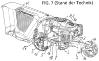
- Fig. 7 shows in one of the Fig. 1 corresponding view a conventional lawn mower, which instead of the electric motor in the lawn mower according to the invention the Fig. 1 to 6 has an internal combustion engine 1' as a drive motor 1 for the cutting tool 2 and in which a drive belt 16 is accommodated in the belt space 5, which is coupled to the drive shaft of the internal combustion engine 1'.
- a rear wheel drive 17 can be driven by the internal combustion engine 1' via the drive belt 16.
- this conventional lawn mower essentially corresponds to the lawn mower according to the invention of the Fig. 1 to 6 , whereby identical reference symbols are used for identical or functionally equivalent components for easier understanding and in this respect reference is made to the explanations of the Fig. 1 to 6 can be referred to.
- the mower housing 3 can be used in a substantially identical manner for the two mower versions, any modifications can concern the accommodation of the combustion engine and associated peripheral components such as carburettor etc. and an optional combustion engine cooling instead of the cooling air duct 6.
- the fan 7 is missing in this conventional lawn mower as is the cooling air duct 6, and the drive belt is coupled to the drive shaft of the combustion engine 1' approximately where at the lawn mower according to the invention the Fig. 1 to 6 the fan 7 is coupled to the drive shaft 1a of the electric motor.
- the lawn mower according to the invention includes a cooling air guide 6 in the mower housing 3 with an air inlet 6a, an air outlet 6b and an air guide path 6c from the air inlet 6a to the air outlet 6b.
- a fan 7 that can be driven by the electric motor 1 is arranged in the air guide path 6c, the belt space 5 forming part of the air guide path 6c.
- cooling air guide 6 cooling air can be guided along the air guide path 6c from the air inlet 6a to the air outlet 6b as a cooling air flow, as in the Fig. 1 and 3 is schematically indicated by a dashed flow line KL.
- the lawn mower can be equipped with a conventional clippings collection container 11, which can be detachably attached to the mower housing 3 and into which a mowing channel 12, which is bordered by the mowing deck 3a and carries the mown clippings, opens.
- the mowing channel 12 is designed separately from the belt space 5 in this lower part of the mower housing 3.
- the lawn mower is designed as a hand-held lawn mower with two rear wheels 13 and two front wheels 14, which is guided by the user via a guide rod (not shown).
- the belt space 5 extends from a drive shaft area 8 of the mower housing 3 to a wheel drive area 9 of the mower housing 3. Consequently, the part of the air guide path 6c formed by the belt space 5 leads from the drive shaft area 8 of the mower housing 3 to the wheel drive area 9 of the mower housing 3.
- the drive shaft area 8 is the area of the mower housing 3 in which the drive shaft 1a of the drive motor 1 is located
- the wheel drive area 9 is the area of the mower housing 3 in which a wheel drive coupled to the drive shaft 1a of the drive motor 1 via the drive belt is located when the combustion engine is used as the drive motor 1.
- the wheel drive area 9 is located in a rear part of the mower housing 3, so that in this case the wheel drive drives the rear wheels 13 of the lawn mower, whereby the lawn mower is self-propelled and does not need to be pushed by the user.
- the lawn mower can also be self-propelled, for example by arranging an additional electric motor in the wheel drive area 9, separate from the drive motor 1 for the cutting tool.
- the blower 7 and the cutting tool 2 are arranged coaxially on the drive shaft 1a, i.e. both sit together on the drive shaft 1a, whereby in the example shown the blower 7 is arranged between the motor body of the drive motor 1 and the cutting tool 2.
- the blower 7 can, for example, be coupled to the drive shaft 1a at the point at which the drive belt, which is then accommodated in the belt space 5, is coupled to the drive shaft 1a when the lawn mower is equipped with the combustion engine instead of the electric motor as the drive motor 1.
- the fan 7, as in the example shown is a radial fan with a fan rotation axis parallel to the drive shaft 1a of the drive motor 1, so that the cooling air leaves the area of the fan 7 essentially perpendicular to the fan rotation axis.
- the fan 7 in this case has a fan housing which widens radially outwards with a funnel-shaped region 7a and then opens into the belt space 5.
- the belt space 5 as in the example shown, extends substantially parallel to a plane of rotation of the cutting tool 2, i.e. perpendicular to a rotation axis RA of the cutting tool 2. This means that in this case the part of the air guide path 6c formed by the belt space 5 also extends parallel to the plane of rotation of the cutting tool 2.
- the belt space 5 extends adjacent to a hood roof side 10 of the mower deck 3a.
- the belt space 5 extends specifically adjacent to the top of the hood roof side 10 of the mower deck 3a from the drive shaft area 8 of the mower housing 3 to the rear to the wheel drive area 9 of the mower housing located in the rear part of the mower housing 3.
- the belt compartment 5 is separated downwards from the open mowing side 4 by a removable cover 15, which forms a corresponding part of the hood roof side 10 of the mowing deck 3a.
- Fig. 5 the cover 15 can be seen mounted
- Fig. 6 shows the same view with cover 15 removed. In the view of Fig.
- the belt chamber 5 leads away from the funnel-shaped region 7a of the fan housing with an end region 5a on the drive shaft side and forms the corresponding part of the air guide path 6c of the cooling air guide 6 with a channel-shaped region 5b.
- the air inlet 6a and the air outlet 6b are located, as in the example shown in the Fig. 1 to 6 , outside the mower deck 3a.
- the air inlet 6a is located in an upper area of the mower housing 3, as in the example shown.
- the air outlet 6b is located in a lower rear area of the mower housing 3 outside the mower deck 3a, as in the example shown.
- the air outlet 6b can be located at the corresponding wheel drive end of the belt chamber 5, i.e. the cooling air escapes from the mower housing 3 to the outside at the end of the belt chamber 5 via the air outlet 6b there.
- the air outlet 6b can be located, for example, in a lower front area of the mower housing 3 outside the mower deck 3a, particularly if the mower has a front-wheel drive when equipped with the combustion engine, which is coupled to the drive shaft 1a of the drive motor 1 via the drive belt then arranged.
- the mower housing 3 as in the example shown, has Fig. 1 to 6 , a motor housing 3b arranged on the mowing deck 3a, in which the drive motor 1 is arranged.
- the motor housing 3b is detachably mounted on the mowing deck 3a and can be removed from it if necessary.
- the mower housing 3 or the motor housing 3b can be modified as required to accommodate the combustion engine instead of the electric motor. It is also understood that the mower housing 3 or the motor housing 3b adapted to the use of the internal combustion engine or the electric motor can be designed to accommodate means for the corresponding energy supply of the drive motor 1, such as an associated battery pack or another electrical energy supply for the electric motor or a petrol tank for the internal combustion engine.
- the air inlet is located specifically at the upper, rear area of the engine housing 3b, while the air outlet 6b is located at a lower, rear part of the mower housing 3, which forms the mowing deck 3a on the underside and in which the belt space 5 is formed.
- the invention provides a motor-driven lawn mower which has a mower housing with a hood-shaped mowing deck and a belt space formed outside the mowing deck and in which the mower housing can be used in an identical manner both for a version of the lawn mower with the combustion engine as the drive motor and for a version of the lawn mower with the electric motor as the drive motor, wherein a cooling air duct is formed in the mower housing, in particular for cooling the electric motor, to the air duct of which the belt space contributes, without in this case the drive belt being accommodated in the belt space.
Landscapes
- Life Sciences & Earth Sciences (AREA)
- Environmental Sciences (AREA)
- Harvester Elements (AREA)
Priority Applications (2)
| Application Number | Priority Date | Filing Date | Title |
|---|---|---|---|
| EP23185078.5A EP4491004A1 (fr) | 2023-07-12 | 2023-07-12 | Tondeuse à gazon motorisée et utilisation de boîtier de tondeuse |
| US18/770,169 US20250017141A1 (en) | 2023-07-12 | 2024-07-11 | Motorized Lawnmower, and Use of Mower Housing |
Applications Claiming Priority (1)
| Application Number | Priority Date | Filing Date | Title |
|---|---|---|---|
| EP23185078.5A EP4491004A1 (fr) | 2023-07-12 | 2023-07-12 | Tondeuse à gazon motorisée et utilisation de boîtier de tondeuse |
Publications (1)
| Publication Number | Publication Date |
|---|---|
| EP4491004A1 true EP4491004A1 (fr) | 2025-01-15 |
Family
ID=87280237
Family Applications (1)
| Application Number | Title | Priority Date | Filing Date |
|---|---|---|---|
| EP23185078.5A Pending EP4491004A1 (fr) | 2023-07-12 | 2023-07-12 | Tondeuse à gazon motorisée et utilisation de boîtier de tondeuse |
Country Status (2)
| Country | Link |
|---|---|
| US (1) | US20250017141A1 (fr) |
| EP (1) | EP4491004A1 (fr) |
Citations (6)
| Publication number | Priority date | Publication date | Assignee | Title |
|---|---|---|---|---|
| US20030182919A1 (en) * | 2002-03-28 | 2003-10-02 | Baumann James R. | Deck assembly for a self-propelled, walk-behind rotary lawn mower |
| JP3776771B2 (ja) * | 2001-08-22 | 2006-05-17 | 本田技研工業株式会社 | 電動作業機 |
| CN108142103A (zh) | 2016-12-06 | 2018-06-12 | 苏州宝时得电动工具有限公司 | 电动工具 |
| EP3659420A1 (fr) | 2017-09-20 | 2020-06-03 | Honda Motor Co., Ltd. | Unité électrique |
| EP3673722A1 (fr) | 2018-12-25 | 2020-07-01 | Changzhou Globe Co., Ltd. | Outil de jardin et son ensemble d'alimentation |
| CN215421683U (zh) * | 2021-04-28 | 2022-01-07 | 浙江鸿泰园林机械有限公司 | 一种皮带冷却的割草机 |
-
2023
- 2023-07-12 EP EP23185078.5A patent/EP4491004A1/fr active Pending
-
2024
- 2024-07-11 US US18/770,169 patent/US20250017141A1/en active Pending
Patent Citations (6)
| Publication number | Priority date | Publication date | Assignee | Title |
|---|---|---|---|---|
| JP3776771B2 (ja) * | 2001-08-22 | 2006-05-17 | 本田技研工業株式会社 | 電動作業機 |
| US20030182919A1 (en) * | 2002-03-28 | 2003-10-02 | Baumann James R. | Deck assembly for a self-propelled, walk-behind rotary lawn mower |
| CN108142103A (zh) | 2016-12-06 | 2018-06-12 | 苏州宝时得电动工具有限公司 | 电动工具 |
| EP3659420A1 (fr) | 2017-09-20 | 2020-06-03 | Honda Motor Co., Ltd. | Unité électrique |
| EP3673722A1 (fr) | 2018-12-25 | 2020-07-01 | Changzhou Globe Co., Ltd. | Outil de jardin et son ensemble d'alimentation |
| CN215421683U (zh) * | 2021-04-28 | 2022-01-07 | 浙江鸿泰园林机械有限公司 | 一种皮带冷却的割草机 |
Also Published As
| Publication number | Publication date |
|---|---|
| US20250017141A1 (en) | 2025-01-16 |
Similar Documents
| Publication | Publication Date | Title |
|---|---|---|
| DE69534144T2 (de) | Universaler, nachrüstbarer motorblock für kleine benzinbrennkraftmaschine | |
| DE69117212T2 (de) | Rasenmäher | |
| DE3530557C2 (fr) | ||
| EP0985439B1 (fr) | Dispositif de nettoyage pour un filtre rotatif d'air de refroidissement | |
| DE2926725B2 (de) | Kuhlluftfilter für den Brennkraftmotor, insbesondere fur selbstfahrende landwirtschaftliche Maschinen | |
| EP0079399A1 (fr) | Dispositif de nettoyage pour nettoyer le filtre à air d'un carter d'air de refroidissement avec un radiateur comprenant un ventilateur | |
| DE102007044770A1 (de) | Rasenmäher | |
| DE112017008228B4 (de) | Motor-integrierte getriebevorrichtung | |
| DE3232895C2 (de) | Sichelrasenmäher mit elektrischem Antrieb | |
| DE69331841T2 (de) | Rasenmäher | |
| EP4491004A1 (fr) | Tondeuse à gazon motorisée et utilisation de boîtier de tondeuse | |
| DE19542860A1 (de) | Mulchmäher | |
| DE102020125814B4 (de) | Schneideinheit für eine motorsense | |
| DE102020207031B4 (de) | Rasenmäher | |
| EP1181858B1 (fr) | Système de coupe et de déchiquetage pour tondeuse à gazon | |
| DE19850260C2 (de) | Rasenmäher mit Sammelvorrichtung für das Schnittgut | |
| EP0630553A1 (fr) | Arrangement d'entraînement d'un appareil, pour une combinaison véhicule-appareil | |
| DE102013223822B4 (de) | Fahrwerksantriebsvorrichtung einer Gartenbearbeitungsmaschine | |
| DE10219181B4 (de) | Schneidkopf für eine motorbetriebene Vorrichtung zum Schneiden von Pflanzen | |
| DE202012102708U1 (de) | Gartenarbeitsgerät | |
| DE2552083B2 (de) | Saugmähgerät | |
| EP1510122B1 (fr) | Tracteur-tondeuse avec dispositif de fauchage et canal de décharge | |
| DE69708778T2 (de) | Rasenmäher mit Gras-Auffangbox | |
| EP4230352B1 (fr) | Appareil de travail portatif | |
| EP1493905A1 (fr) | Dispositif de nettoyage pour l'air de refroidissement |
Legal Events
| Date | Code | Title | Description |
|---|---|---|---|
| PUAI | Public reference made under article 153(3) epc to a published international application that has entered the european phase |
Free format text: ORIGINAL CODE: 0009012 |
|
| STAA | Information on the status of an ep patent application or granted ep patent |
Free format text: STATUS: THE APPLICATION HAS BEEN PUBLISHED |
|
| AK | Designated contracting states |
Kind code of ref document: A1 Designated state(s): AL AT BE BG CH CY CZ DE DK EE ES FI FR GB GR HR HU IE IS IT LI LT LU LV MC ME MK MT NL NO PL PT RO RS SE SI SK SM TR |
|
| STAA | Information on the status of an ep patent application or granted ep patent |
Free format text: STATUS: REQUEST FOR EXAMINATION WAS MADE |
|
| 17P | Request for examination filed |
Effective date: 20250516 |