EP4491008A1 - Machine de fenaison - Google Patents
Machine de fenaison Download PDFInfo
- Publication number
- EP4491008A1 EP4491008A1 EP24179168.0A EP24179168A EP4491008A1 EP 4491008 A1 EP4491008 A1 EP 4491008A1 EP 24179168 A EP24179168 A EP 24179168A EP 4491008 A1 EP4491008 A1 EP 4491008A1
- Authority
- EP
- European Patent Office
- Prior art keywords
- tine
- spring
- measuring means
- haymaking machine
- spring tine
- Prior art date
- Legal status (The legal status is an assumption and is not a legal conclusion. Google has not performed a legal analysis and makes no representation as to the accuracy of the status listed.)
- Granted
Links
Images



Classifications
-
- G—PHYSICS
- G01—MEASURING; TESTING
- G01L—MEASURING FORCE, STRESS, TORQUE, WORK, MECHANICAL POWER, MECHANICAL EFFICIENCY, OR FLUID PRESSURE
- G01L5/00—Apparatus for, or methods of, measuring force, work, mechanical power, or torque, specially adapted for specific purposes
- G01L5/0057—Apparatus for, or methods of, measuring force, work, mechanical power, or torque, specially adapted for specific purposes measuring forces due to spring-shaped elements
-
- A—HUMAN NECESSITIES
- A01—AGRICULTURE; FORESTRY; ANIMAL HUSBANDRY; HUNTING; TRAPPING; FISHING
- A01D—HARVESTING; MOWING
- A01D78/00—Haymakers with tines moving with respect to the machine
- A01D78/08—Haymakers with tines moving with respect to the machine with tine-carrying rotary heads or wheels
- A01D78/10—Haymakers with tines moving with respect to the machine with tine-carrying rotary heads or wheels the tines rotating about a substantially vertical axis
- A01D78/1078—Having only one row of rotors arranged on the same horizontal line perpendicular to the advance direction of the machine
-
- A—HUMAN NECESSITIES
- A01—AGRICULTURE; FORESTRY; ANIMAL HUSBANDRY; HUNTING; TRAPPING; FISHING
- A01D—HARVESTING; MOWING
- A01D80/00—Parts or details of, or accessories for, haymakers
- A01D80/02—Tines; Attachment of tines
Definitions
- the invention relates to a haymaking machine for tedding or raking agricultural stalks or leaves according to the preamble of patent claim 1.
- Such haymaking machines are known from the prior art in various designs and are used to spread and turn agricultural stalks and leaves lying on a field or meadow to support the drying process or to gather them into swaths so that subsequent harvesting machines can collect the harvested material and process it further.
- tine arms fitted with one or more spring tines fitted to tedders or swathers must reach into and work the crop during the rotation of the tedder or swather.
- the working height of the spring tines is ideally selected so that their tine tips lift the crop off the grass stubble. However, to avoid unwanted contamination of the forage, the tine tips should not penetrate the soil.
- a rotary rake is known in which the height of the rake tines of the rotary rakes is adjusted depending on the harvest mass gathered in a swath, the moisture of the harvested crop and the vibration intensity of the rake tines. All criteria for determining the rotor height are based on the conveying conditions during the lateral The actual distance between the tine tips of the rake tines and the ground is not taken into account, so that the risk of unwanted forage contamination or crop losses due to crops remaining lying around is high.
- the object of the present invention is to improve a haymaking machine in such a way that the monitoring effort for the operator during the harvesting process is reduced, feed contamination and crop losses are avoided and the work result is optimized.
- a haymaking machine for tedding or raking agricultural stalks or leaves with at least one tedding or raking rotor arranged on a machine beam, which is driven in a working and operating position so as to rotate around an approximately vertical axis, and is provided with at least two or more tine arms evenly distributed in a circumferential direction around the vertical axis and approximately radially aligned, wherein at least one first spring tine is arranged on the tine arms, which has a first length, and wherein at least one second spring tine is arranged on the tedding or raking rotor, which has a second length which is smaller than the first length, wherein the tedding or raking rotor comprises at least one first measuring means which interacts with the first spring tine, as well as a second measuring device which interacts with the second spring tine, the measuring devices each being provided for measuring a force acting on the respective spring tine.
- the invention thus opens up the possibility of clearly detecting whether or not the spring tine of a tine arm of a tedder or rake of the haymaking machine comes into contact with the ground in the field or meadow during work.
- a clear difference arises between the normal conveyance of the stalk and leaf material during tedding or raking and the tine tip of one of the spring tines coming into contact with the ground.
- This difference can be determined as the difference between the measuring signals of the first measuring device on the first spring tine and the second measuring device on the second spring tine.
- the measured signals determined are thus forwarded to a control device of the haymaking machine connected to the first measuring device and the second measuring device.
- control parameters are generated which are fed to an adjustment device for adjusting the distance between the tine tips of the spring tines of the rotary tedder or rake.
- one tine arm of a rotary tedder or rake is preferably provided, to which a first spring tine with a first measuring device and a second spring tine with a second measuring device are attached.
- the force acting on the respective spring tine is recorded by measuring a torque and/or a change in position and/or a deformation of the respective spring tine.
- the measurement of the force acting on the respective spring tine by determining a torque or a change in position is based on the fact that the force acting on the tine tip of the spring tine causes a torque around the tine arm or the tine arm wants to change position under the influence of the force.
- These are mechanical reactions that can be measured using simple means.
- the force acting on the respective spring tine is determined by detecting a deformation of the spring tine. The invention thus uses a simple and cost-effective measuring method.
- the first and second measuring devices are connected at one end to the tine arm and at the other end to the respective spring tine.
- the spring tines are arranged in pairs.
- the tine pairs are provided with a resilient fastening section from which the spring tines extend towards the ground.
- Each of the tine pairs can be spatially assigned to an outer end of the tine arm.
- the spring tines of tine pairs arranged further inside or spring tines of different tine pairs can also be used for the measurement. This design can be used advantageously on rotary rakes, since a number of rake tines are arranged at the end of a tine arm to carry out the raking work.
- the first measuring device on the first spring tine of the tine pair and the second measuring device on the second spring tine of the tine pair.
- the spring tines of the second tine pair are to be designed with a second length that is smaller than a first length of the first tine pair. This embodiment is also advantageously applicable to raking work.
- the first and second measuring devices are designed as strain gauge sensors.
- Strain gauge sensors have the advantage that they are easy to attach to spring tines and that they provide an electrical voltage as an output signal. This provides a measurement signal that can be easily evaluated and further processed.
- a control device for evaluating the measurement signals, which is assigned to the haymaking machine.
- the control device can of course also be attached to a tractor or similar traction and drive machine driving the haymaking machine via an ISOBUS connection.
- the control device is connected to the first and second measuring devices for further processing of the measurement signals and is used to determine a difference between the measuring signals from the first and second measuring devices. The difference between the measuring signals thus provides a clear control parameter for controlling the working height of the tine tips of the spring tines of rotary tedders or rakes.
- the haymaking machine is provided with an adjustment device for adjusting the distance between the tine tip of a spring tine and the ground.
- This adjustment device can be assigned directly to the tedder or rake rotor or can act on the tedder or rake rotor via kinematic lever deflections from the machine beam of the haymaking machine.
- the control device forwards control parameters to the adjustment device, so that the control device is set up to adjust the distance of the tedder or rake rotor depending on the difference in the measurement signals.
- the adjustment device can also be designed to adjust an angle of the tedder or rake rotor in relation to the ground. Control parameters of the control device are also used for this purpose, which are determined based on the difference in the measurement signals.
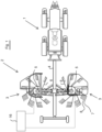
- FIG. 1 A working train is visible, consisting of a tractor 1 and a haymaking machine 2 attached to it in the form of a rotary swather.
- Haymaking machines of this type are designed to gather widely distributed stalks or leaves into swaths, so that subsequent harvesting machines can pick up the stalks or leaves lying in swaths and process them further.
- the haymaking machine 2 is provided with tedders or rakes 3, which are hinged to a machine beam 4 and are driven in rotation about an approximately vertical axis 5. It can also be seen that the tedders or rakes 3 are evenly distributed in the direction of rotation and are equipped with tine arms 6 aligned radially outwards.
- the direction of rotation is selected such that, viewed in the direction of travel, the tedders or rakes 3 converge towards each other at their front towards the middle, with the swath being formed in the area between the tedders or rakes 3.
- the haymaking machine 2 comprises an adjustment device 16.
- the adjustment device 16 can be directly associated with the tedder or rake 3.
- An embodiment is also conceivable in which an adjustment device is provided which acts on the tedder or rake 3 from the machine beam 2 of the haymaking machine 2.
- Fig. 2 shows a first embodiment of a tine arm 6 of the tedder or rake 3 of the haymaking machine 2, on which a plurality of spring tines 20 are arranged.
- Measuring devices 10 are attached to two of the spring tines 20.
- These spring tines 20 are referred to below as the first spring tine 7 and the second spring tine 8.
- the first and second spring tines 7, 8 are arranged here at an outer end 15 of the tine arm 6. However, they can also be arranged further inside on the tine arm 6.
- the first spring tine 7 and the second spring tine 8 can be spaced apart from one another by one or more further spring tines 20.
- the spring tines 20, 7, 8 are attached to the tine arm 6 via a fastening section 9 which is spatially assigned to the tine arm 6 and is designed to be resilient and are connected to it in a rotationally fixed manner.
- a first measuring device 10 is mounted on the first spring tine 7 and a second measuring device 11 is mounted on the second spring tine 8.
- the measuring devices 10, 11 are preferably mounted in an upper area facing the fastening section 9 of an approximately rod-shaped section of the first and second spring tines 7, 8, which extends from the fastening section 9 to the ground.
- Fig. 2 is that the first spring tine 7 has a rod-shaped section with a first length 12 and the second spring tine 8 has a rod-shaped section with a second length 13. Due to the difference between the first length 12 and the second length 13, it is possible during operation of the haymaking machine according to the invention for a clear difference between the measurement signals at the first spring tine 7 and at the second spring tine 8 to be measured.
- the analogous effect can also be achieved with a tine arm 6 in which only one spring tine 20, which serves as the first spring tine 7 and has a measuring device 10, is longer than all the other spring tines 20.
- One of the other spring tines 20 serves as the second spring tine 8 and therefore also has a measuring device 10.
- control device 17 By evaluating the measurement signals by means of the control device 17, control parameters are generated which are fed to the setting device 16 in order to carry out an automatic control of a distance of a tine tip of a spring tine 7, 8 from the ground and/or an adjustment angle in relation to the ground.
- a second embodiment of a tine arm 6 is shown, on which tine pairs 14, each having two spring tines 20, are attached to the tine arm 6 at equal intervals, starting from the outer end 15 of the tine arm 6.
- the tine pair 14 at the outer end 15 of the tine arm 6 has a first spring tine 7, and a further tine pair 14 has a second spring tine 8, on which the measuring means 10, 11 are arranged.
- the two spring tines 20 of the tine pair 14 at the outer end 15 of the tine arm 6 each have a rod-shaped section with a first length 12, while the spring tines 20 of the further tine pair 14 each comprise a rod-shaped section with a second length 13.
- the second length 13 is smaller than the first length 12.
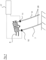
- Fig. 4 shows an embodiment of a further tine arm 6, on which a first spring tine 7 with a first measuring device 10 and a second spring tine 8 with a second measuring device 11 are arranged.
- This embodiment illustrated here is preferably used for tedding agricultural stalks or leaves.
- different measuring signals from the first measuring device 10 and the second measuring device 11 are sent to a control device 17 forwarded in order to be able to be fed to the setting device 16 of the haymaking machine 2 after appropriate evaluation and conversion into control parameters.
- This makes it possible to automatically control a distance of a tine tip of a spring tine 7,8 from the ground and/or an angle of adjustment in relation to the ground.
- FIG. 5 Two diagrams are shown with signal curves 18, 19 of the measurement signals that were measured by the first measuring device 10 on the first spring tine 7 and by the second measuring device 11 on the second spring tine 8.
- a first signal curve 18 is shown in a solid line and is recorded by the first measuring device 10.
- a second signal curve 19 is shown in dotted lines and is recorded by the second measuring device 11.
- the vertical axes of the diagrams are divided into digits with a constant scale, which correspond to an electrical voltage.
- the horizontal axes of the diagrams represent a time axis.
- the signal curves 18,19 are shown, which arise when the longer, here first spring tine 7 touches the ground of the field or meadow area during cultivation.
- the level of the measurement signal of the signal curve 18 in the right diagram is significantly increased.
- a significant difference can thus be determined between the measurement signal of the first measuring device 10 of the first spring tine 7 and the measurement signal of the second measuring device 11 of the second spring tine 8.
- This significant difference between the measurement signals allows, after appropriate evaluation by the control device 17, a reliable, automatic control of a distance of a tine tip of a spring tine 7, 8 from the ground and/or an angle of adjustment in relation to the ground.
Landscapes
- Life Sciences & Earth Sciences (AREA)
- Environmental Sciences (AREA)
- Physics & Mathematics (AREA)
- General Physics & Mathematics (AREA)
- Guiding Agricultural Machines (AREA)
- Soil Working Implements (AREA)
Priority Applications (1)
| Application Number | Priority Date | Filing Date | Title |
|---|---|---|---|
| SI202430014T SI4491008T1 (sl) | 2023-07-14 | 2024-05-31 | Stroj za spravilo sena |
Applications Claiming Priority (1)
| Application Number | Priority Date | Filing Date | Title |
|---|---|---|---|
| DE102023118727.9A DE102023118727A1 (de) | 2023-07-14 | 2023-07-14 | Heuwerbungsmaschine |
Publications (2)
| Publication Number | Publication Date |
|---|---|
| EP4491008A1 true EP4491008A1 (fr) | 2025-01-15 |
| EP4491008B1 EP4491008B1 (fr) | 2025-12-03 |
Family
ID=91375350
Family Applications (1)
| Application Number | Title | Priority Date | Filing Date |
|---|---|---|---|
| EP24179168.0A Active EP4491008B1 (fr) | 2023-07-14 | 2024-05-31 | Machine de fenaison |
Country Status (7)
| Country | Link |
|---|---|
| US (1) | US20250020525A1 (fr) |
| EP (1) | EP4491008B1 (fr) |
| AU (1) | AU2024204800A1 (fr) |
| DE (1) | DE102023118727A1 (fr) |
| DK (1) | DK4491008T3 (fr) |
| PL (1) | PL4491008T3 (fr) |
| SI (1) | SI4491008T1 (fr) |
Citations (4)
| Publication number | Priority date | Publication date | Assignee | Title |
|---|---|---|---|---|
| DE1457989A1 (de) * | 1962-11-24 | 1969-02-13 | Fella Werke Gmbh | Heuwerbungsmaschine |
| DE20107541U1 (de) * | 2001-05-03 | 2002-09-19 | Niemeyer Landmaschinen GmbH, 48477 Hörstel | Kreiselheuer |
| EP2850934A2 (fr) | 2013-09-24 | 2015-03-25 | CLAAS Saulgau GmbH | Andaineuse rotative |
| EP3909417A1 (fr) * | 2020-05-15 | 2021-11-17 | CNH Industrial Belgium N.V. | Système de ratissage agricole et procédé de réglages automatiques |
-
2023
- 2023-07-14 DE DE102023118727.9A patent/DE102023118727A1/de active Pending
-
2024
- 2024-05-31 EP EP24179168.0A patent/EP4491008B1/fr active Active
- 2024-05-31 PL PL24179168.0T patent/PL4491008T3/pl unknown
- 2024-05-31 SI SI202430014T patent/SI4491008T1/sl unknown
- 2024-05-31 DK DK24179168.0T patent/DK4491008T3/da active
- 2024-07-09 US US18/766,681 patent/US20250020525A1/en active Pending
- 2024-07-11 AU AU2024204800A patent/AU2024204800A1/en active Pending
Patent Citations (4)
| Publication number | Priority date | Publication date | Assignee | Title |
|---|---|---|---|---|
| DE1457989A1 (de) * | 1962-11-24 | 1969-02-13 | Fella Werke Gmbh | Heuwerbungsmaschine |
| DE20107541U1 (de) * | 2001-05-03 | 2002-09-19 | Niemeyer Landmaschinen GmbH, 48477 Hörstel | Kreiselheuer |
| EP2850934A2 (fr) | 2013-09-24 | 2015-03-25 | CLAAS Saulgau GmbH | Andaineuse rotative |
| EP3909417A1 (fr) * | 2020-05-15 | 2021-11-17 | CNH Industrial Belgium N.V. | Système de ratissage agricole et procédé de réglages automatiques |
Also Published As
| Publication number | Publication date |
|---|---|
| DK4491008T3 (da) | 2026-02-02 |
| DE102023118727A1 (de) | 2025-01-16 |
| EP4491008B1 (fr) | 2025-12-03 |
| SI4491008T1 (sl) | 2026-03-31 |
| AU2024204800A1 (en) | 2025-01-30 |
| US20250020525A1 (en) | 2025-01-16 |
| PL4491008T3 (pl) | 2026-04-20 |
Similar Documents
| Publication | Publication Date | Title |
|---|---|---|
| EP1374661B1 (fr) | Procédé et appareil pour le réglage de la position d'un dispositif ramasseur dans une récolteuse | |
| EP2859787B1 (fr) | Procédé d'utilisation d'un dispositif de cueillette avec plaques de cueillette à distances variables | |
| EP2545761B1 (fr) | Procédé de fonctionnement d'une moissonneuse automobile | |
| EP2733680B1 (fr) | Procédé de fonctionnement d'une moissonneuse autotractée | |
| EP2286657B1 (fr) | Machine agricole | |
| EP2850934B1 (fr) | Andaineuse rotative | |
| EP3607815B1 (fr) | Appareil de traitement agricole | |
| DE102010010861A1 (de) | Landmaschine | |
| EP3729949B1 (fr) | Chariot de chargement à détection de rendement de la récolte | |
| DE102008001779B4 (de) | Erntevorsatz mit einem Gutaufnehmer und einer Querförderschnecke | |
| EP4494446A1 (fr) | Machine de fenaison | |
| EP4491008B1 (fr) | Machine de fenaison | |
| EP3892085B1 (fr) | Procédé de fonctionnement d'une andaineuse multirotative et andaineuse multirotative | |
| EP4380347A1 (fr) | Tête de ramassage destinée à une récolteuse-hacheuse de préférence autotractée | |
| BE1026594B1 (de) | Anordnung zur Einstellung der Position der Gegenschneide eines Feldhäckslers | |
| EP4548741A1 (fr) | Procédé de traitement de champ | |
| EP4410087B1 (fr) | Moissonneuse agricole automotrice | |
| DE102010047071B4 (de) | Heuwerbungsmaschine | |
| WO2023227169A1 (fr) | Accessoire de ramassage pour machine de récolte | |
| EP4124236B1 (fr) | Andaineuse dotée d'un râteau rotatif à réglage d'inclinaison | |
| DE102023113953A1 (de) | Verfahren zum Betreiben eines Gespanns | |
| WO2023116973A1 (fr) | Accessoire de ramassage pour une moissonneuse | |
| EP4122311A1 (fr) | Andaineuse rotative | |
| DE10315226A1 (de) | Erntemaschine mit Mähwerk zur lokal diskreten Erfassung des Ertrages von Futterpflanzen | |
| DE7715979U1 (de) | Feldhaecksler |
Legal Events
| Date | Code | Title | Description |
|---|---|---|---|
| PUAI | Public reference made under article 153(3) epc to a published international application that has entered the european phase |
Free format text: ORIGINAL CODE: 0009012 |
|
| STAA | Information on the status of an ep patent application or granted ep patent |
Free format text: STATUS: THE APPLICATION HAS BEEN PUBLISHED |
|
| AK | Designated contracting states |
Kind code of ref document: A1 Designated state(s): AL AT BE BG CH CY CZ DE DK EE ES FI FR GB GR HR HU IE IS IT LI LT LU LV MC ME MK MT NL NO PL PT RO RS SE SI SK SM TR |
|
| STAA | Information on the status of an ep patent application or granted ep patent |
Free format text: STATUS: REQUEST FOR EXAMINATION WAS MADE |
|
| 17P | Request for examination filed |
Effective date: 20250617 |
|
| GRAP | Despatch of communication of intention to grant a patent |
Free format text: ORIGINAL CODE: EPIDOSNIGR1 |
|
| STAA | Information on the status of an ep patent application or granted ep patent |
Free format text: STATUS: GRANT OF PATENT IS INTENDED |
|
| RIC1 | Information provided on ipc code assigned before grant |
Ipc: A01D 78/10 20060101AFI20250808BHEP Ipc: A01D 80/02 20060101ALI20250808BHEP |
|
| INTG | Intention to grant announced |
Effective date: 20250901 |
|
| GRAS | Grant fee paid |
Free format text: ORIGINAL CODE: EPIDOSNIGR3 |
|
| GRAA | (expected) grant |
Free format text: ORIGINAL CODE: 0009210 |
|
| STAA | Information on the status of an ep patent application or granted ep patent |
Free format text: STATUS: THE PATENT HAS BEEN GRANTED |
|
| AK | Designated contracting states |
Kind code of ref document: B1 Designated state(s): AL AT BE BG CH CY CZ DE DK EE ES FI FR GB GR HR HU IE IS IT LI LT LU LV MC ME MK MT NL NO PL PT RO RS SE SI SK SM TR |
|
| REG | Reference to a national code |
Ref country code: CH Ref legal event code: F10 Free format text: ST27 STATUS EVENT CODE: U-0-0-F10-F00 (AS PROVIDED BY THE NATIONAL OFFICE) Effective date: 20251203 Ref country code: GB Ref legal event code: FG4D Free format text: NOT ENGLISH |
|
| REG | Reference to a national code |
Ref country code: DE Ref legal event code: R096 Ref document number: 502024000450 Country of ref document: DE |
|
| REG | Reference to a national code |
Ref country code: IE Ref legal event code: FG4D Free format text: LANGUAGE OF EP DOCUMENT: GERMAN |
|
| REG | Reference to a national code |
Ref country code: DK Ref legal event code: T3 Effective date: 20260126 |
|
| P01 | Opt-out of the competence of the unified patent court (upc) registered |
Free format text: CASE NUMBER: UPC_APP_0019623_4491008/2025 Effective date: 20251230 |
|
| REG | Reference to a national code |
Ref country code: NL Ref legal event code: MP Effective date: 20251203 |
|
| PG25 | Lapsed in a contracting state [announced via postgrant information from national office to epo] |
Ref country code: ES Free format text: LAPSE BECAUSE OF FAILURE TO SUBMIT A TRANSLATION OF THE DESCRIPTION OR TO PAY THE FEE WITHIN THE PRESCRIBED TIME-LIMIT Effective date: 20251203 |
|
| REG | Reference to a national code |
Ref country code: LT Ref legal event code: MG9D |
|
| PG25 | Lapsed in a contracting state [announced via postgrant information from national office to epo] |
Ref country code: NO Free format text: LAPSE BECAUSE OF FAILURE TO SUBMIT A TRANSLATION OF THE DESCRIPTION OR TO PAY THE FEE WITHIN THE PRESCRIBED TIME-LIMIT Effective date: 20260303 |
|
| PG25 | Lapsed in a contracting state [announced via postgrant information from national office to epo] |
Ref country code: FI Free format text: LAPSE BECAUSE OF FAILURE TO SUBMIT A TRANSLATION OF THE DESCRIPTION OR TO PAY THE FEE WITHIN THE PRESCRIBED TIME-LIMIT Effective date: 20251203 Ref country code: HR Free format text: LAPSE BECAUSE OF FAILURE TO SUBMIT A TRANSLATION OF THE DESCRIPTION OR TO PAY THE FEE WITHIN THE PRESCRIBED TIME-LIMIT Effective date: 20251203 |
|
| PG25 | Lapsed in a contracting state [announced via postgrant information from national office to epo] |
Ref country code: RS Free format text: LAPSE BECAUSE OF FAILURE TO SUBMIT A TRANSLATION OF THE DESCRIPTION OR TO PAY THE FEE WITHIN THE PRESCRIBED TIME-LIMIT Effective date: 20260303 |
|
| PG25 | Lapsed in a contracting state [announced via postgrant information from national office to epo] |
Ref country code: LV Free format text: LAPSE BECAUSE OF FAILURE TO SUBMIT A TRANSLATION OF THE DESCRIPTION OR TO PAY THE FEE WITHIN THE PRESCRIBED TIME-LIMIT Effective date: 20251203 |