EP4491083A1 - Élément de tête de nettoyage, ensemble de nettoyage de surface et appareil de nettoyage humide - Google Patents
Élément de tête de nettoyage, ensemble de nettoyage de surface et appareil de nettoyage humide Download PDFInfo
- Publication number
- EP4491083A1 EP4491083A1 EP23185129.6A EP23185129A EP4491083A1 EP 4491083 A1 EP4491083 A1 EP 4491083A1 EP 23185129 A EP23185129 A EP 23185129A EP 4491083 A1 EP4491083 A1 EP 4491083A1
- Authority
- EP
- European Patent Office
- Prior art keywords
- porous layer
- cleaner head
- underpressure
- porous
- liquid
- Prior art date
- Legal status (The legal status is an assumption and is not a legal conclusion. Google has not performed a legal analysis and makes no representation as to the accuracy of the status listed.)
- Withdrawn
Links
Images











Classifications
-
- A—HUMAN NECESSITIES
- A47—FURNITURE; DOMESTIC ARTICLES OR APPLIANCES; COFFEE MILLS; SPICE MILLS; SUCTION CLEANERS IN GENERAL
- A47L—DOMESTIC WASHING OR CLEANING; SUCTION CLEANERS IN GENERAL
- A47L11/00—Machines for cleaning floors, carpets, furniture, walls, or wall coverings
- A47L11/40—Parts or details of machines not provided for in groups A47L11/02 - A47L11/38, or not restricted to one of these groups, e.g. handles, arrangements of switches, skirts, buffers, levers
- A47L11/4036—Parts or details of the surface treating tools
- A47L11/4044—Vacuuming or pick-up tools; Squeegees
-
- A—HUMAN NECESSITIES
- A47—FURNITURE; DOMESTIC ARTICLES OR APPLIANCES; COFFEE MILLS; SPICE MILLS; SUCTION CLEANERS IN GENERAL
- A47L—DOMESTIC WASHING OR CLEANING; SUCTION CLEANERS IN GENERAL
- A47L13/00—Implements for cleaning floors, carpets, furniture, walls, or wall coverings
- A47L13/10—Scrubbing; Scouring; Cleaning; Polishing
- A47L13/20—Mops
- A47L13/22—Mops with liquid-feeding devices
-
- A—HUMAN NECESSITIES
- A47—FURNITURE; DOMESTIC ARTICLES OR APPLIANCES; COFFEE MILLS; SPICE MILLS; SUCTION CLEANERS IN GENERAL
- A47L—DOMESTIC WASHING OR CLEANING; SUCTION CLEANERS IN GENERAL
- A47L9/00—Details or accessories of suction cleaners, e.g. mechanical means for controlling the suction or for effecting pulsating action; Storing devices specially adapted to suction cleaners or parts thereof; Carrying-vehicles specially adapted for suction cleaners
- A47L9/02—Nozzles
- A47L9/06—Nozzles with fixed, e.g. adjustably fixed brushes or the like
- A47L9/0686—Nozzles with cleaning cloths, e.g. using disposal fabrics for covering the nozzle
Definitions
- This invention relates to a cleaner head member for a wet cleaning apparatus.
- the invention also relates to a surface cleaning assembly comprising the cleaner head member and a cleaner head.
- the invention further concerns a wet cleaning apparatus comprising the cleaner head member or the surface cleaning assembly.
- the cleaner head member, surface cleaning assembly and wet cleaning apparatus can be used, for example, for cleaning a floor, an indoor surface, or a window.
- wet cleaning apparatuses for example wet mopping devices, which remove water from a surface to be cleaned.
- Such wet cleaning apparatuses can also apply cleaning liquid, e.g. water, to the surface to be cleaned, and then remove the liquid, e.g. with a suitable cloth.
- wet cleaning apparatuses have powered pick-up functionality for removing the water from the surface to be cleaned.
- Wet vacuum cleaners may pick up liquid by generating sufficient airspeed (e.g. at least 10 m/s) and/or brushpower to exert enough shear force on liquid droplets to cause them to enter the device.
- Typical power consumption values for such vacuum cleaners are relatively high, for example in the order of several hundred watts.
- a further challenge can arise when the wet cleaning apparatus is arranged to deliver cleaning liquid as well as pick up the liquid using suction. Providing both functionalities can, in at least some designs, risk that the cleaning liquid is used inefficiently.
- a cleaner head member for a cleaner head of a wet cleaning apparatus, the cleaner head member comprising a porous layer suitable for being subjected to an underpressure generated by an underpressure generator included in the wet cleaning apparatus, the porous layer having a limiting pore diameter, as measured using ASTM F316 - 03, 2019, Test A, equal to or less than 105 ⁇ m, pores of the porous layer extending across the porous layer's thickness and opening out at opposite sides of the porous layer, a linear central axis of each pore extending across the thickness and passing through an intermediate point surrounded by a pore wall of the respective pore, the pore wall being arranged about the linear central axis, a path of least resistance to fluid flow across the porous layer being defined along the linear central axes of the pores.
- the porous layer When the porous layer is dry, the porous layer may be regarded as being in an "air transport state” in which air is transported through each of the dry pores of the porous layer.
- a “liquid transport state” corresponds to liquid, e.g. water, being transported through the (wetted) pores of the porous layer.
- a “fluid block state” When there is no longer a feed of liquid to the pores, a “fluid block state” may be adopted.
- the “fluid block state” corresponds to the state at which the surface tension of the (residual) liquid retained in the wetted pores of the porous layer prevents fluid transport through the pores.
- a surface or barrier is created at the boundary between air and liquid, e.g. water. This barrier can assist to maintain the underpressure between the porous layer and the underpressure generator. The pressure needed to "break” this barrier can be termed a “breaking pressure”.
- the 105 ⁇ m upper limit for the limiting pore diameter equivalent to a minimum bubble point pressure of 2000 Pa, may assist to ensure that sufficient underpressure is maintainable by the porous layer.
- Pores of the porous layer whose linear central axis extends across the porous layer's thickness and passes through an intermediate point surrounded by a pore wall of the respective pore, are considered to be better defined than, for example, pores defined between fibers of a woven fabric.
- the present disclosure is at least partly based on the insight that such better-defined pores can be selected to be physically larger than less well-defined pores of other types of porous materials, but still provide a comparable breaking pressure. Since the better-defined pores can be made physically larger while achieving a given breaking pressure, they may be less liable to become clogged by dirt particles.
- pores of the porous layer may have a pore size distribution that can be selected to be separate from, in other words not overlapping with, a pore size distribution of a further porous layer arranged on the porous layer.
- the pore size distribution of the porous layer may be shifted to larger pore sizes than the pore size distribution of the further porous layer.
- Clogging of the further porous layer by such dirt particles may be addressed by, for example, detachment of the further porous layer from the porous layer to enable cleaning and/or replacement of the further porous layer.
- Each pore of the porous layer can be regarded as a through-hole that axially extends through the thickness of the porous layer.
- Such pores can be defined in any suitable manner, for example by laser ablation of a polymeric membrane, or by a woven structure of a mesh, e.g. a monofilament mesh.
- pores of the porous layer each have a polygonal or circular cross-sectional shape perpendicular to the linear central axis.
- pores of the porous layer may each have a square cross-sectional shape perpendicular to the linear central axis.
- Such a polygonal, e.g. square, or circular cross-sectional shape perpendicular to the linear central axis may mean that the pore wall provides a consistent surface, in particular a relatively well-defined rim between a surface of the pore wall and exterior surface(s) of one or both sides of the porous layer. This can assist to increase the breaking pressure.
- the rim between a surface of the pore wall and an exterior surface of the porous layer may, for example, have a radius of curvature of 0.1 ⁇ m to 3 ⁇ m.
- Such a radius of curvature which may be significantly smaller than the pore radius, may assist to prevent the size of the liquid-air interface/surface from growing when pressure is applied. This may prevent the increase in force on the surface (force being equal to pressure multiplied by area), hence may prevent the surface's edge from being overloaded sooner, thereby keeping the surface from collapsing/"exploding".
- the pores having the polygonal, e.g. square, or circular cross-sectional shape may provide a higher breaking pressure even with a relatively large pore size. This larger pore size, in turn, can assist to alleviate pore blockages by dirt particles.
- a circular cross-sectional shape with the pore being generally cylindrical, or a polygonal, e.g. square, cross-sectional shape, with the pore being generally prismatic, e.g. cubic or cuboidal, can assist to provide a pore geometry-related increase in breaking pressure.
- the well-defined pores of the porous layer contrast with the pores defined between fibers of a woven fabric in which a range of contact angles are effectively provided around the surfaces delimiting a given pore.
- the shapes of the upstream and downstream openings of such a woven fabric pore are also not as well-defined as the upstream and downstream rims of the porous layer. This means that in the case of a pore of a woven fabric, there may always be a place in the pore where the contact angle reaches its limit so that the liquid barrier can no longer maintain its position.
- the resultant barrier movement may enlarge the surface area on which the pressure acts; the total force on the barrier increasing, making it harder for the rest of the barrier to maintain its position, with further movement resulting, and so on. This issue may be addressed by the well-defined pore geometry of each of the pores of the porous layer according to embodiments of the present disclosure.
- a contact angle between liquid and the surface of the porous layer may always be present; an increase in pressure may move an edge of the barrier to a new position of equilibrium; if this shifting occurs while the barrier remains relatively small, higher breaking pressures can be obtained; if the shifting occurs while significantly increasing the surface area of the barrier, the breaking pressure may be lower.
- the thickness of the porous layer is less than 200 ⁇ m, preferably less than 100 ⁇ m. Such a maximum thickness may contribute to minimizing of flow resistance through the porous layer.
- the porous layer comprises, e.g. is, a mesh.
- the porous layer may comprise, e.g. be, a perforate membrane.
- Such a mesh e.g. a monofilament mesh, and/or perforate membrane may represent a relatively straightforward way of providing pores with the above-mentioned well-defined geometry.
- pores may for example be defined by subjecting a membrane, e.g. a polymer membrane, to laser ablation.
- the pores may have the above-mentioned polygonal, e.g. square, or circular cross-sectional shape.
- the pores may be defined by the manner in which the wires, e.g. polymer wires, of the mesh are woven and/or welded.
- the pores may have, for example, the above-mentioned square cross-sectional shape.
- the porous layer comprises, e.g. is, a plain weave woven mesh or a twill weave woven mesh. Both plain weave and twill weave may provide pores with the square cross-sectional shape.
- plain weave may provide a higher breaking pressure than twill weave.
- the plain weave mesh may allow for larger pores than the twill weave mesh.
- the porous layer is formed from a material having a water contact angle less than 90°. Such a contact angle may mean that the porous layer is suitably wettable by aqueous liquid on the surface to be cleaned.
- the porous layer is formed from a polyester and/or a polyamide.
- Such materials have been found to be suitably hydrophilic to enable the porous layer to be adequately wetted by water, e.g. water received from the surface being cleaned.
- the hydrophilicity of polyamide e.g. nylon, may be particularly suitable for the porous layer.
- Polyester may also provide suitable hydrophilicity, particularly following plasma treatment of the polyester.
- the cleaner head member comprises a support member for supporting the porous layer.
- the porous layer may be affixed, e.g. adhered, to the support member.
- the cleaner head member may include a pliable material on which the porous layer is arranged. Deformation, e.g. resilient deformation, of such a pliable material may lessen the risk of damage to the porous layer should, for example, a relatively hard protrusion be present on the surface to be cleaned which comes into contact with the porous layer, or the further porous layer arranged on the porous layer. Alternatively or additionally, the pliable material may assist the porous layer to follow any contours of the surface to be cleaned.
- the cleaner head member may be resiliently mounted or mountable to the cleaner head. This may assist the porous layer to follow any contours of the surface to be cleaned, thereby facilitating liquid pick-up.
- the pliable material comprises a curved surface on which the porous layer is arranged, with the porous layer following the curvature of the curved surface.
- the pliable material defines the support member that supports the porous layer. In other embodiments, the pliable material is arranged between the support member, e.g. rigid support member, and the porous layer.
- one or more dirt inlet(s) is or are defined in the cleaner head member, the porous layer covering the one or more dirt inlet(s).
- the dirt inlet(s) may fluidly connect the underpressure generator with the pores of the porous layer.
- a liquid pick-up region of the porous layer may be delimited by sealing attachment of the porous layer around the at least one dirt inlet.
- the sealing attachment of the porous layer around the dirt inlet(s) may assist to maintain an underpressure in the dirt inlet(s) with or without the flow being applied by the underpressure generator included in the wet cleaning apparatus.
- the sealing attachment can be implemented in any suitable manner, such as by gluing or welding the porous layer around each of the at least one dirt inlet, for example gluing and/or welding the porous layer around one or more tubes whose opening(s) define the dirt inlet(s).
- the at least one dirt inlet is defined by one or more channels extending through the pliable material.
- the cleaner head member is attachable and/or detachable to the cleaner head of the wet cleaning apparatus.
- the porous layer may be susceptible to wear, and such wear can risk compromising the underpressure-maintaining/liquid pick-up performance of the porous layer.
- replacement of the porous layer may be rendered difficult for a user because of the above-described sealing attachment of the porous layer around the dirt inlet(s).
- the cleaner head member may comprise the porous layer already sealingly attached to the dirt inlet(s).
- the cleaner head member enables replacement of the porous layer without requiring the user to himself re-seal the porous layer to the dirt inlet(s). This can assist to avoid a scenario where faulty sealing of the porous layer to the dirt inlet(s) by the user precludes or hampers subsequent operation of the wet cleaning apparatus.
- the cleaner head member may be configured to be detachably coupled to the wet cleaning apparatus.
- the cleaner head member can itself be straightforwardly replaced or cleaned, e.g. when the porous layer needs to be replaced or cleaned, by detachment of the cleaner head member from the cleaner head of the wet cleaning apparatus.
- the limiting pore diameter of the porous layer as measured using ASTM F316 - 03, 2019, Test A is at least 6 ⁇ m, preferably at least 8 ⁇ m, most preferably at least 11 ⁇ m.
- a limiting pore diameter equal to or greater than 6 ⁇ m may assist to maintain a relatively large underpressure whilst ensuring that pores still enable efficient liquid transport therethrough.
- the latter may also be assisted by minimizing the thickness of the porous layer, for example to less than 200 ⁇ m, preferably less than 150 ⁇ m.
- the physical pore size of pores of the porous layer e.g. at least 6 ⁇ m, corresponding to such a limiting pore diameter of at least 6 ⁇ m, may be larger than that of pores of the further porous layer, e.g. woven fabric layer(s), e.g. around 3 ⁇ m.
- the limiting pore diameter of the porous layer as measured using ASTM F316 - 03, 2019, Test A is 11 to 15 ⁇ m.
- a surface cleaning assembly comprising: the cleaner head member according to any of the embodiments described herein; and a cleaning material for contacting a surface to be cleaned, the cleaning material comprising a further porous layer for arranging on the porous layer.
- the further porous layer may comprise one or more woven fabric layers.
- the pore size distribution of the porous layer spans a range of pore sizes whose smallest pore size is larger than a largest pore size of a range of pore sizes spanned by the further porous layer, e.g. woven fabric layer(s).
- the further porous layer e.g. woven fabric layer(s) has a limiting pore diameter, as measured using ASTM F316 - 03, 2019, Test A, equal to or less than 105 ⁇ m and/or equal to or greater than 15 ⁇ m.
- a limiting pore diameter of the further porous layer e.g. woven fabric layer(s), as measured using ASTM F316 - 03, 2019, Test A equal to or greater than 15 ⁇ m may assist to maintain a relatively large underpressure whilst ensuring that pores are sufficiently large for efficient liquid transport through the further porous layer.
- a bubble point pressure of the further porous layer as measured using ASTM F316 - 03, 2019, Test A may be equal to or less than 13500 Pa.
- a limiting pore diameter of the further porous layer as measured using ASTM F316 - 03, 2019, Test A is equal to or less than 105 ⁇ m. This upper limit for the limiting pore diameter assists to ensure that sufficient underpressure is maintainable by the further porous layer.
- a bubble point pressure of the further porous layer as measured using ASTM F316 - 03, 2019, Test A may be equal to or greater than 2000 Pa.
- the bubble point pressure of the further porous layer is 7000 Pa to 9000 Pa.
- Fluid transporting pores of the porous layer and/or the liquid pick-up region may be exclusively arranged in a region of the porous layer that remains in contact with the further porous layer when the surface cleaning assembly is assembled with the further porous layer being arranged on the porous layer.
- the maintaining of contact between the further porous layer and the porous layer may mean that any "broken" pores in the porous layer may be kept supplied with liquid from the further porous layer, and thereby "repaired". This can assist maintenance of the underpressure between the underpressure generator and the porous layer.
- the further porous layer has a porous structure configured to enable lateral fluid transport in a first direction within the further porous layer as well as fluid transport in a second direction across a thickness of the further porous layer towards the porous layer.
- the lateral fluid transport provided in the further porous layer e.g. the woven fabric layer(s) of the further porous layer, can assist to keep the porous layer supplied with liquid, thereby helping to repair broken pores of the porous layer.
- a pore may remain “broken” as long as the underpressure to which the porous layer is subjected is above the pore's breaking pressure. Should the underpressure fall below the breaking pressure, the pore may draw liquid from its surroundings to close itself up again, in other words so as to be "repaired, thereby reinstating the fluid block state.
- the self-repairability may be particularly effective when the porous layer is in contact with a woven fabric layer.
- porous layers e.g. meshes, with a relatively small pore size may also be capable of repairing themselves.
- a mesh having a pore size of 11 ⁇ m may provide broken pore repairability that is almost identical to that of the woven fabric layer
- a mesh having a pore size of 15 ⁇ m may provide broken pore repairability that is close to that provided by a woven fabric layer, but may be less consistent.
- a mesh having a pore size of 18 ⁇ m may, however, provide significantly worse broken pore repairability than that provided by a woven fabric layer.
- At least the further porous layer of the cleaning material is detachable from the porous layer.
- the further porous layer e.g. along with the rest of the cleaning material, can be detached for cleaning and/or replacement.
- the cleaning material may further comprise a cleaning liquid applicator material configured to apply cleaning liquid to the surface to be cleaned.
- a wet cleaning apparatus comprising: the cleaner head member according to any of the embodiments described herein or the surface cleaning assembly according to any of the embodiments described herein; and an underpressure generator for subjecting the porous layer to an underpressure.
- the underpressure generator may be configured to provide a pressure difference between an inside of the wet cleaning apparatus and atmospheric pressure for drawing fluid through the porous layer, with the pressure difference being in a range of 2000 Pa to 15000 Pa, preferably 2000 Pa to 13500 Pa.
- the underpressure generator may be configured to generate a flow through the porous layer that is at most 2000 cm 3 /minute.
- the underpressure generator is configured to supply said suction by providing a flow through the porous layer in the range of 15 to 2000 cm 3 /minute, more preferably 80 to 750 cm 3 /minute, even more preferably 100 to 300 cm 3 /minute, and most preferably 150 to 300 cm 3 /minute.
- Such a flow i.e. flow rate
- the underpressure generator may, for example, comprise a positive displacement pump, such as a peristaltic pump.
- a positive displacement pump can assist to maintain the underpressure in the dirt inlet(s) after the underpressure generator has been deactivated, e.g. switched off, because the pump design inherently restricts backflow from the pump outlet. This, in turn, may alleviate problematic liquid release from the porous layer, for instance following cleaning of the surface to be cleaned and/or during stowing of the wet cleaning apparatus in a storage area after use.
- the wet cleaning apparatus may include a dirty liquid collection tank.
- the underpressure generator may be arranged to draw liquid from the at least one dirt inlet to the dirty liquid collection tank.
- the wet cleaning apparatus comprises a cleaning liquid supply for supplying cleaning liquid for delivery towards the surface to be cleaned via at least one cleaning liquid outlet, e.g. included in the cleaner head.
- Such a cleaning liquid supply may, for example, comprise a cleaning liquid reservoir and a delivery arrangement, e.g. a delivery arrangement comprising a pump, for transporting the cleaning liquid to and through the at least one cleaning liquid outlet.
- a delivery arrangement e.g. a delivery arrangement comprising a pump
- the cleaning liquid supply and the at least one cleaning liquid outlet may be configured to provide a continuous delivery of the cleaning liquid towards the surface to be cleaned.
- Such continuous delivery may, for instance, be provided at the same time as underpressure generator is supplying suction to the at least one dirt inlet.
- the cleaning liquid supply and the underpressure generator may, for instance, be configured such that the flow of the cleaning liquid delivered through the at least one cleaning liquid outlet is equal to or lower than the flow provided to the at least one dirt inlet by the underpressure generator. This may assist to ensure that the surface to be cleaned does not become excessively wet with the cleaning liquid.
- the flow of cleaning liquid may be in the range of 20 to 100 cm 3 /minute
- the flow provided by the underpressure generator may be in the range of 40 to 2000 cm 3 /minute, more preferably 80 to 750 cm 3 /minute, even more preferably 100 to 300 cm 3 /minute, and most preferably 150 to 300 cm 3 /minute.
- the wet cleaning apparatus may comprise, for example, a wet mopping device, a window cleaner, a sweeper, or a wet vacuum cleaner, such as canister-type, stick type, or upright type wet vacuum cleaner.
- the wet cleaning apparatus may in some examples comprise a robotic wet vacuum cleaner or a robotic wet mopping device configured to autonomously move the cleaner head on the surface to be cleaned, such as the surface of a floor. Particular mention is made of a wet mopping device.
- the wet cleaning apparatus is a battery-powered (or battery-powerable) wet cleaning apparatus, such as a battery-powered (or battery-powerable) wet mopping device, in which the underpressure generator, e.g. pump, is powered (or powerable) by a battery electrically connected (or connectable) thereto.
- the underpressure generator e.g. pump
- the underpressure generator e.g. pump
- the cleaner head member for a wet cleaning apparatus.
- the cleaner head member comprises a porous layer suitable for being subjected to an underpressure generated by an underpressure generator included in the wet cleaning apparatus. Pores of the porous layer extend across the porous layer's thickness and open out at opposite sides of the porous layer, with a linear central axis of each pore extending across the thickness and passing through an intermediate point surrounded by a pore wall of the respective pore; the pore wall being arranged about the linear central axis. A path of least resistance to fluid flow across the porous layer is defined along the linear central axes of the pores.
- a surface cleaning assembly comprising the cleaner head member.
- a wet cleaning apparatus comprising the cleaner head member or the surface cleaning assembly.
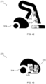
- FIG. 1 shows a cleaner head 100 according to a non-limiting example.
- an underside 102 of the cleaner head 100 is shown in FIG. 1 .
- the underside 102 faces a surface to be cleaned (not visible in FIG. 1 ) using the cleaner head 100.
- At least one cleaning liquid outlet 104 included in the cleaner head 100.
- Cleaning liquid is deliverable through the, e.g. each of, the at least one cleaning liquid outlet 104.
- the at least one cleaning liquid outlet need not to be provided on the underside 102 of the cleaner head 100, and may alternatively be provided elsewhere in the cleaner head 100 provided that the cleaning liquid can be delivered via the cleaning liquid outlet(s) to reach the surface to be cleaned.
- the cleaning liquid can comprise, or consist of, water.
- the cleaning liquid can be an aqueous cleaning liquid.
- the cleaning liquid is an aqueous detergent solution.
- the cleaning liquid outlets 104 are arranged in a row along a length 106 of the cleaner head 100. This may assist the cleaner head 100 to wet the surface to be cleaned with the cleaning liquid along the length 106 of the cleaner head 100. It should nonetheless be noted that any suitable configuration or pattern of cleaning liquid outlets 104 can be contemplated, provided that other parts of the cleaner head 100 can be accommodated.
- sixteen cleaning liquid outlets 104 are included in the cleaner head 100, noting that more cleaning liquid outlets 104 may assist to increase the uniformity of wetting of the surface to be cleaned.
- any suitable number of cleaning liquid outlets 104 may be provided in the cleaner head 100, for example one, two, three, four, five, six, seven, eight, nine, ten, eleven, twelve, thirteen, fourteen, fifteen, sixteen, seventeen, eighteen, nineteen, twenty, or more.
- the cleaner head 100 comprises a cleaning liquid distribution strip 108. At least some, or in this example all, of the cleaning liquid outlets 104 may be included in the cleaning liquid distribution strip 108, as shown.
- FIG. 2 provides a cross-sectional view of the cleaning liquid distribution strip 108 included in the exemplary cleaner head 100 shown in FIG. 1 .
- the cleaning liquid distribution strip 108 comprises a channel 110 which can be supplied with the cleaning liquid, e.g. from a suitable cleaning liquid reservoir (not visible in FIG. 2 ) via an inlet 112.
- the inlet 112 is provided at or proximal to an end of the cleaning liquid distribution strip 108 in the example shown in FIG. 2 , however it is also conceivable that the inlet 112 is provided in a central position along the length of the cleaning liquid distribution strip 108.
- the cleaning liquid distribution strip 108 comprises a plurality of inlets 112, for example a pair of inlets 112 arranged at opposite ends of the cleaning liquid distribution strip 108.
- the cleaning liquid may exit the cleaning liquid distribution strip 108 via apertures in the cleaning liquid distribution strip 108 which define the cleaning liquid outlets 104.
- Such apertures may be dimensioned such that passage of the cleaning liquid, e.g. aqueous cleaning liquid, through the apertures is restricted, due to the surface tension of the cleaning liquid, while the channel 110 is being filled, but with passage of the cleaning liquid through all of the apertures of the cleaning liquid distribution strip 108 at the same time being permitted once the channel 110 has been filled. This may enable relatively uniform wetting of the surface to be cleaned across the length 106 of the cleaner head 100.
- each cleaning liquid outlet 104 may have, for example, a diameter less than 1 mm, for example a diameter in the range of 0.1 to 1 mm, preferably 0.1 to 0.8 mm, most preferably 0.1 to 0.5 mm, such as about 0.3 mm.
- the cleaning liquid distribution strip 108 can be formed of any suitable material, such as a metal, a metal alloy, e.g. stainless steel, and/or a polymer. Forming the cleaning liquid distribution strip 108 from a polymer can make the cleaning liquid distribution strip 108 more lightweight and/or cheaper to manufacture.
- the cleaner head 100 may include a porous layer 114. Whilst not visible in FIG. 1 , the cleaner head 100 has at least one dirt inlet. Each of the dirt inlet(s) is covered by the porous layer 114.
- porous layer 114 may be included, or in some embodiments define, a cleaner head member.
- Such a cleaner head member may, for example, be attachable to and/or detachable from the cleaner head 100.
- the surface tension of the liquid retained in the pores of the porous layer 114 can assist to maintain the underpressure. This surface tension can be overcome at a point (or points) on the external surface 116 of the porous layer 114 which come into contact with liquid, thereby causing the liquid to be transported through the porous layer 114 in the direction of the dirt inlet(s), as will be explained in more detail herein below.
- the porous layer 114 may be arranged between the dirt inlet(s) and the surface to be cleaned such that dirty liquid on the surface to be cleaned is first transported into the pores of the porous layer 114, and then passes from the porous layer 114 into the dirt inlet(s).
- FIG. 1 shows an external surface 116 of the porous layer 114, which external surface 116 faces, albeit may not itself contact, the surface to be cleaned.
- the porous layer 114 covering each of the at least one dirt inlet may assist to maintain an underpressure in the dirt inlet(s) with or without constant flow being applied thereto, for instance by an underpressure generator, e.g. pump, fluidly connected to the dirt inlet(s).
- an underpressure generator e.g. pump
- the porous layer 114 is elongated such as to have a largest dimension extending parallel with the length 106 of the cleaner head 100.
- the porous layer 114 is positioned at a different location along the width 118 of the cleaner head 100 with respect to the cleaning liquid outlets 104.
- the cleaner head 100 comprises a portion 120 for facing the surface to be cleaned.
- One or more of the cleaning liquid outlets 104 may be arranged to deliver the cleaning liquid to the portion 120 of the cleaner head 100.
- a protruding element may be mounted adjacent the portion 120, with the protruding element protruding from the cleaner head 100 in the direction of the surface to be cleaned.
- the protruding element can be regarded as an element mounted separately in the cleaner head 100 with respect to the portion 120.
- the protruding element is included, together with the porous layer 114, in the cleaner head member.
- the protruding element may have limited contact with the surface to be cleaned.
- the protruding element may, for example, have a smaller area of contact with the surface to be cleaned than the portion 120.
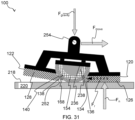
- the protruding element comprises the porous layer 114. Resistance to motion of the cleaner head 100 across the surface to be cleaned may therefore be lessened due to the limited area of contact between porous material, albeit not necessarily specifically the porous layer, and the surface to be cleaned. This will be described in further detail herein below with reference to FIG. 31 .
- the cleaner head 100 can be rocked on the protruding element in a first direction to cause the portion 120 to contact the surface to be cleaned, and rocked on the protruding element in a second direction opposite to the first direction to cause the portion 120 to be separated from the surface to be cleaned.
- the protruding element can be regarded as a rocker which permits the cleaner head 100 to be rocked onto the portion 120.
- the protruding element has limited contact with the surface to be cleaned.
- the cleaner head 100 comprises the portion 120 and a further portion 122 for facing the surface to be cleaned.
- the porous layer 114 may be arranged between the portion 120 and the further portion 122.
- the protruding element may be mounted between the portion 120 and the further portion 122.
- the protruding element may thus be an element mounted separately with respect to both the portion 120 and the further portion 122. In this way, the cleaner head 100 can be rocked forwards on the protruding element to cause the portion 120 to contact the surface to be cleaned, and backwards to cause the further portion 122 to contact the surface to be cleaned.
- the cleaning liquid outlet(s) 104 may be arranged to deliver the cleaning liquid to the portion 120 and the further portion 122 of the cleaner head 100.
- the cleaner head 100 comprises a cleaning liquid distribution strip 108 whose apertures define cleaning liquid outlets 104 which deliver the cleaning liquid to the portion 120, as described above in relation to FIGs. 1 and 2 , and a further cleaning liquid distribution strip 124 whose further apertures define cleaning liquid outlets 104 which deliver the cleaning liquid to the further portion 122.
- Both the cleaning liquid distribution strip 108 and the further cleaning liquid distribution strip 124 may extend parallel with the length 106 of the cleaner head 100, as shown in FIG. 3 .
- the cleaner head 100 comprises a cleaning liquid applicator material 126, 128 adjacent each of the at least one cleaning liquid outlet 104, with the cleaning liquid applicator material 126, 128 being arranged to apply the cleaning liquid to the surface to be cleaned.
- the cleaning liquid applicator material 126, 128 may receive the cleaning liquid delivered from the cleaning liquid outlet(s) 104, and transfer the cleaning liquid to the surface to be cleaned.
- the cleaning liquid applicator material 126, 128 can, for example, comprise polyamide and/or polyester fibers.
- the cleaning liquid applicator material 126, 128 comprises a combination of thinner fibers and thicker fibers.
- the thinner fibers can, for example, be less than or equal to 1 decitex, and the thicker fibers can have a thickness greater than 0.01 mm, for example the thickness of the thicker fibers can be about 0.05 mm.
- the thicker fibers which can be made from polyamide or polyester, may assist to reduce friction between the cleaning liquid applicator material 126, 128 and the surface to be cleaned, while the thinner fibers, e.g. made from polyamide or polyester, may assist to enhance dirt retention.
- the thicker fibers may also provide resilience to the cleaning liquid applicator material 126, 128, thereby minimising compaction of the cleaning liquid applicator material 126, 128.
- the compaction-reducing capability of the thicker fibers may be of particular utility in embodiments in which cleaning liquid applicator material 126, 128 is included in the portion 120 and/or the further portion 122 adjacent the protruding element rocker. This is because minimised compaction may assist to ensure that, over continued use of the cleaner head 100, a consistent degree of rocking on the protruding element causes the cleaning liquid applicator material 126, 128 to contact the surface to be cleaned.
- the thickness of the cleaning liquid applicator material 126, 128 may alternatively or additionally be selected or limited, e.g. in view of the degree of protrusion of the protruding element relative to the portion 120 and/or the further portion 122, such as to minimise compaction of the cleaning liquid applicator material 126, 128 during use of the cleaner head 100.
- the cleaning liquid applicator material 126, 128 comprises the combination of thinner fibers and thicker fibers
- these fibers can be arranged relative to each other in any suitable manner.
- the cleaning liquid applicator material 126, 128 may comprise a strip of thicker fibers adjacent a strip of thinner fibers. Such strips may each extend along the length 106 of the cleaner head 100, such that the fiber thickness alternates in the width 118 direction. Such a configuration may assist to reduce friction when the cleaner head 100 is moved in directions parallel to the width 118 direction.
- the cleaning liquid applicator material 126, 128 comprises both polyamide and polyester fibers
- these fibers can be arranged relative to each other in any suitable manner.
- the cleaning liquid applicator material 126, 128 may comprise a strip of polyamide fibers adjacent a strip of polyester fibers. Such strips may each extend along the length 106 of the cleaner head 100, such that the fiber type alternates in the width 118 direction.
- the cleaning liquid applicator material 126, 128 can, for instance, comprise a backing layer which supports the material, e.g. polyamide and/or polyester fiber-comprising material, which contacts the surface to be cleaned.
- the backing layer can be formed of any suitable backing fabric material, such as polyester.
- Such a backing layer can be supplied with tufts, e.g. formed from polyamide and/or polyester fibers. Such tufts can assist the cleaning liquid applicator material 126, 128 to follow the contours of the surface to be cleaned and/or may assist the cleaning liquid applicator material 126, 128 to retain dirt particles whilst also minimising the risk of scratching the surface to be cleaned.
- the cleaning liquid applicator material 126, 128 is detachable from each of the at least one cleaning liquid outlet 104. This may enable replacement of the cleaning liquid applicator material 126, 128, for example once the cleaning liquid applicator material 126, 128 has become overly worn, and/or enable the cleaning liquid applicator material 126, 128 to be washed between uses.
- the cleaning liquid applicator material 126, 128 can be attached to the cleaner head 100, in particular to the underside 102 of the cleaner head 100 in the non-limiting examples shown in FIGs. 1 to 4 , in any suitable manner.
- the depicted cleaner head 100 comprises at least one fastening member 130A, 130B, 132A, 132B, in this example in the form of Velcro strips, which engage with further fastening member(s) (not visible), on the cleaning liquid applicator material 126, 128.
- the further fastening member(s) can, for example, be included in, or affixed to, the above-described backing layer of the cleaning liquid applicator material 126, 128.
- the cleaning liquid applicator material 126, 128 comprises a first applicator portion 126 and a second applicator portion 128, with the porous layer 114 being arranged between the first applicator portion 126 and the second applicator portion 128.
- the first applicator portion 126 When the first applicator portion 126 is included in the cleaner head 100, the first applicator portion 126 may be included in the above-described portion 120 of the cleaner head 100.
- the portion may be suitable for both contacting the surface to be cleaned and assisting to clean the surface to be cleaned, e.g. by assisting in the application of cleaning liquid to the surface to be cleaned.
- the portion 120 may nonetheless be suitable for contacting the surface to be cleaned (in the sense that it is possible for the portion 120 to be brought into contact with the surface to be cleaned without the portion 120 being required to include the cleaning liquid applicator material), albeit with potentially less cleaning capability than the scenario in which the cleaning liquid applicator material, e.g. the first applicator portion 126, is included in the portion 120.
- the first applicator portion 126 can include the above-described further fastening member(s) which engage(s) with the fastening member(s) 130A, 130B provided on the cleaner head 100 for incorporating the first applicator portion 126 in the portion 120.
- the second applicator portion 128 when included in the cleaner head 100, the second applicator portion 128 may be included in the above-described further portion 122 of the cleaner head 100.
- the second applicator portion 128 can include the above-described further fastening member(s) which engage(s) with the fastening member(s) 132A, 132B provided on the cleaner head 100 for incorporating the second applicator portion 128 in the further portion 122.
- the at least one cleaning liquid outlet 104 comprises at least one pair of cleaning liquid outlets 104, with the porous layer 114 being arranged between the cleaning liquid outlets 104 of each pair.
- the cleaning liquid applicator material 126, 128 comprises the first applicator portion 126 and the second applicator portion 128, the first applicator portion 126 may be adjacent one of the cleaning liquid outlets 104 of said pair, with the second applicator portion 128 being adjacent the other of the cleaning liquid outlets 104 of said pair. An example of this is shown in FIGs. 3 and 4 .
- porous material whose pores carry liquid to the dirt inlet, albeit not necessarily specifically the porous layer 114 included in the porous material, contacts the cleaning liquid applicator fabric 126, 128.
- both of these materials may also be arranged to contact the surface to be cleaned. This may be achieved in any suitable manner.
- an edge portion 134 of the porous material abuts an opposing edge portion 136 of the cleaning liquid applicator material 126, 128.
- the cleaning liquid may first be transported into the cleaning liquid applicator material 126, 128, and only subsequently transported from the cleaning liquid applicator material 126, 128 into the porous material via the abutting edge portions 134, 136 of the respective materials. This may provide enhanced control over the wetness of the cleaning liquid applicator material 126, 128.
- the abutting opposing edge portions 134, 136 of the porous material and the cleaning liquid applicator material 126, 128 are preferably positioned between the protruding element and the portion 120. In this manner, excess cleaning liquid caused to be squeezed from the cleaning liquid applicator material 126, 128 between the protruding element and the cleaning liquid applicator material 126, 128, e.g. by rocking of the cleaner head 100 via the protruding element, may be efficiently transported into the dirt inlet(s) via the porous material.
- the contact between the porous material and the cleaning liquid applicator material 126, 128 may be provided at the surface to be cleaned-contacting side of the materials. This may assist to avoid that the cleaning liquid is passed directly into the porous material without properly wetting the cleaning liquid applicator material 126, 128 or rinsing the porous material.
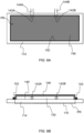
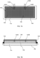
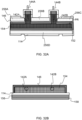
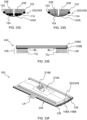
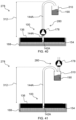
- FIG. 5A provides a plan view showing the porous layer 114 and the at least one dirt inlet 142A, 142B of an exemplary cleaner head 100.
- FIG. 5B provides a schematic cross-sectional view of the porous layer 114 and the at least one dirt inlet 142A, 142B shown in FIG. 5A .
- each of the at least one dirt inlet 142A, 142B is defined by an opening of a tube or tubes 144A, 144B fluidly connected or connectable to an underpressure generator (not visible in FIGs. 5A and 5B ).
- the cleaner head 100 comprises a pair of dirt inlets 142A, 142B, although any suitable number of dirt inlets 142A, 142B can be contemplated, such as one, two, three, four, five, six, or more.
- dirt inlets 142A, 142B When a plurality of dirt inlets 142A, 142B are included in the cleaner head 100, these may, for instance, have the same dimensions as each other.
- the dirt inlets 142A, 142B may be spaced along the length 106 direction of the cleaner head 100 such as to provide relatively uniform suction along the length 106 of the cleaner head 100.
- the distance along the length 106 between a centre position of the cleaner head 100 and a centre of the dirt inlet 142A may be the same, or substantially the same, as the distance along the length 106 between the centre position and a centre of the dirt inlet 142B.
- this may be provided in the central position of the cleaner head 100 to provide a relatively symmetrical suction profile along the length 106 of the cleaner head 100.
- a liquid pick-up region PR of the porous layer 114 may be delimited by sealing attachment of the porous layer 114 around the, e.g. each of the, at least one dirt inlet 142A, 142B.
- Such sealing attachment can assist to maintain an underpressure in the covered dirt inlet(s) 142A, 142B because loss of the underpressure via leakage between the dirt inlet(s) 142A, 142B and the porous layer 114 is minimised or prevented.
- the sealing attachment can be implemented in any suitable manner, such as by gluing and/or welding the porous layer 114 around each of the at least one dirt inlet 142A, 142B, for example gluing and/or welding the porous layer 114 to the above-mentioned tube(s) 144A, 144B around the opening(s) defining the dirt inlet(s) 142A, 142B.
- sealingly attaching the porous layer 114 to the dirt inlet(s) 142A, 142B by heat sealing, for example ultrasonic welding. This has been found to provide a particularly airtight seal in a straightforward manner which assists to maintain the underpressure in the dirt inlet(s) 142A, 142B.
- a non-limiting example of the sealing attachment of the porous layer 114 to the dirt inlets 142A, 142B is implemented by the cleaner head 100 comprising an impermeable portion 146 sealed onto the porous layer 114, for example onto an internal surface 148 of the porous layer 114, and around the dirt inlets 142A, 142B, with the dirt inlets 142A, 142B being thereby exposed to a sealed cavity 150 between the porous layer 114 and the impermeable portion 146.
- the impermeable portion 146 may, for instance, comprise, or consist of, a polymer film, such as a thermoplastic film.
- a polymer film such as a thermoplastic film.
- a seal 152 e.g. formed via adhesive and/or welding of the impermeable portion 146, e.g. polymer film, extends around the periphery of the porous layer 114 and around the dirt inlets 142A, 142B.
- the liquid pick-up region PR is arranged relative to the at least one cleaning liquid outlet 104 such as to allow the cleaning liquid to bypass, e.g. pass around a periphery of, the liquid pick-up region PR to reach, or at least be directed towards, the surface to be cleaned.
- the porous layer 114 can be attached, e.g. against the cleaner head 100 or a component of the cleaner head 100, around the dirt inlet(s) 142A, 142B at least partly by being sucked thereagainst by the flow provided by an underpressure generator.
- the cleaner head 100 comprises a liquid transporting support structure 154 in the cavity 150, with the liquid transporting support structure 154 being arranged to provide one or more flow paths in the liquid pick-up region PR between the porous layer 114, and in particular pores of the porous layer 114, and the at least one dirt inlet 142A, 142B.
- the porous layer 114 and/or the impermeable portion 146 may be pliable such that an underpressure may cause the porous layer 114 and the impermeable portion 146 to be drawn towards each other. This may risk restriction of passage of liquid from the porous layer 114 to the at least one dirt inlet 142A, 142B.
- the liquid transporting support structure 154 may assist to ensure that, in spite of such drawing of the porous layer 114 and the impermeable portion 146 towards each other, liquid can still be transported from the porous layer 114, and in particular pores of the porous layer 114, to the at least one dirt inlet 142A, 142B.
- the liquid transporting support structure 154 may be implemented in any suitable manner.
- the liquid transporting support structure 154 comprises, or is defined by, one or more coarse mesh layers.
- the above-described one or more flow paths can be provided by the spaces between the elements constituting the coarse mesh layer(s).
- Alternative examples of the liquid transporting support structure 154 will be described herein below.
- the porous material can, in some embodiments, comprise one or more further porous layers 156, 158 in addition to the porous layer 114. Examples of this are depicted in FIGs. 8 and 9 .
- the porous material when the porous material is dry, the porous material may be regarded as being in an "air transport state” in which air is transported through each of the dry pores of the porous material.
- a “liquid transport state” corresponds to liquid, e.g. water, being transported through the (wetted) pores of the porous material.
- a “fluid block state” When there is no longer a feed of liquid to the pore(s), a “fluid block state” may be adopted.
- the “fluid block state” corresponds to the state at which the surface tension of the (residual) liquid retained in the wetted pore(s) of the porous material prevents fluid transport through the pore(s).
- a surface or barrier is created at the boundary between air and liquid, e.g. water.
- This barrier can assist to maintain the above-described underpressure in the dirt inlet(s) 142A, 142B.
- the pressure needed to "break” this barrier can be termed a "breaking pressure”.
- the present disclosure is at least partly based on the insight that pore shape may have a very significant impact on the breaking pressure.
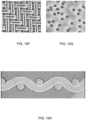
- FIG. 10A provides a photomicrograph that shows yarns of a woven fabric.
- the arrows in FIG. 10A are intended to denote the main liquid transport taking place across such a woven fabric. This main liquid transport may take place through yarns of the fabric.
- pores 159 in such a woven fabric may be defined by individual fibers that are closely packed.
- each of the pores 159 is not very circular, but rather approximates a triangular shape. Moreover, the "end" of such a pore 159 may be poorly defined. The water-air surface needs to "anchor" itself to the pore 159 in order to withstand its full potential in (breaking) pressure. These characteristics, in other words pore shape and pore rim, are considered to have a significant influence on breaking pressure, as described in more detail herein below.
- a pore diameter of a woven fabric was determined by running soiled water through the fabric, with the soiled water containing particles of specified particle size. It was determined that the pores 159 constituting this woven fabric, i.e. cloth, were less than 5 ⁇ m.
- a theoretical model of a pore 159 was developed.
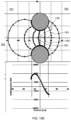
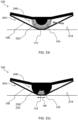
- a pore 159 is described by the center of a donut-shaped element, referring to FIGs 10C and 10D .
- the model uses the following parameters: (i) geometrical information concerning the pore 159 (fiber and pore diameter); (ii) surface tension of water; and (iii) contact angle between water base material, in other words the material constituting the porous layer 114.
- the surface to be cleaned side 160 is separated from the dirt inlet(s) 142A, 142B side 161 by the modelled pore 159, whose cross-section is denoted by the patterned circles.
- Reference numeral 162 denotes liquid, e.g. water. Different positions of water-air membranes are represented by the lines between the patterned circles. The lower graph shown in FIG. 10E shows the pressure difference required to maintain this position.
- the present disclosure concerns definition of the porous layer's 114 pores 159.
- such pores 159 extend across the porous layer's 114 thickness and open out at opposite sides of the porous layer 114, with a linear central axis 163 of each pore 159 extending across the thickness and passing through an intermediate point 164 surrounded by a pore wall 165 of the respective pore 159.
- the pore wall 165 is arranged about the linear central axis 163.
- Each pore 159 of the porous layer 114 can thus be regarded as a through-hole that axially extends through the thickness of the porous layer 114.
- a path of least resistance to fluid flow across the porous layer 114 is defined along the linear central axes 163 of the pores 159.
- Pores 159 of the porous layer 114 whose linear central axis 163 extends across the porous layer's 114 thickness and passes through the intermediate point 164 surrounded by the pore wall 165 of the respective pore 159, are considered to be better defined than, for example, pores 159 defined between fibers of a woven fabric.
- the present disclosure is at least partly based on the insight that such better-defined pores 159 can be selected to be physically larger than less well-defined pores 159 of other types of porous materials, but still provide a comparable breaking pressure. Since the better-defined pores 159 can be made physically larger while achieving a given breaking pressure, they may be less liable to become clogged by dirt particles.
- the pore diameter or D pore of the porous layer 114 is less than 18 ⁇ m.
- the porous layer 114 is a mesh, e.g. a monofilament mesh.
- a mesh e.g. a monofilament mesh.
- FIG. 10F An example of such a mesh, in particular a monofilament mesh, is shown in FIG. 10F .
- the pores 159 may be defined by the manner in which the wires, e.g. polymer wires, of the mesh are woven and/or welded.
- the porous layer 114 is a plain weave woven mesh or a twill weave woven mesh. An example of the latter is shown in FIG. 10F . Both plain weave and twill weave may provide pores 159 with a polygonal, e.g. square, cross-sectional shape.
- plain weave may provide a higher breaking pressure than twill weave.
- the plain weave mesh may allow for larger pores 159 than the twill weave mesh.
- the porous layer 114 is perforate membrane. An example of this is shown in FIG. 10G .
- pores 159 may for example be defined by subjecting a membrane, e.g. a polymer membrane, to laser ablation.
- the pores 159 may have a polygonal, e.g. square, or circular cross-sectional shape.
- Such a mesh for example a monofilament mesh shown in the photomicrograph of FIG. 10H , or perforate membrane may represent a relatively straightforward way of providing pores 159 with the above-mentioned well-defined geometry.
- meshes and perforate membranes may contain significantly better-defined pores 159 than those of a woven fabric (referring again to FIG. 10A ).
- the shape of the pores 159 of the meshes and perforate membranes may be closer to that of the model pore 159 shown in FIGs. 10C to 10E and their rims (anchoring) may be much better defined.
- Table 1 Pore shape Relative physical pore size Example value for physical pore size/ ⁇ m Theoretical pore 159 shown in FIGs. 10C to 10E 1 28.5 Woven plain weave mesh 1.25 22.8 Woven Twill weave mesh 1.55 18.4 Woven fabric 9.5 3
- the porous layer's 114 capability to provide sufficient breaking pressure is captured by its limiting pore diameter, as measured using ASTM F316 - 03, 2019, Test A, being equal to or less than 105 ⁇ m.
- the 105 ⁇ m upper limit for the limiting pore diameter equivalent to a minimum bubble point pressure of 2000 Pa, may assist to ensure that sufficient underpressure is maintainable by the porous layer 114, as explained in more detail herein below.
- the well-defined pores 159 of the porous layer 114 contrast with the pores 159 defined between fibers of a woven fabric in which a range of contact angles are effectively provided around the surfaces delimiting a given pore 159.
- the shapes of the upstream and downstream openings of such a woven fabric pore 159 are also not as well-defined as the upstream and downstream rims of the porous layer 114. This means that in the case of a pore 159 of a woven fabric, there may always be a place in the pore 159 where the contact angle reaches its limit so that the liquid barrier can no longer maintain its position.
- the resultant barrier movement may enlarge the surface area on which the pressure acts; the total force on the barrier increasing, making it harder for the rest of the barrier to maintain its position, with further movement resulting, and so on.
- This issue may be addressed by the well-defined pore geometry of each of the pores 159 of the porous layer 114 according to the present disclosure.
- a contact angle between liquid and the surface of the porous layer 114 may always be present; an increase in pressure may move an edge of the barrier to a new position of equilibrium; if this shifting occurs while the barrier remains relatively small, higher breaking pressures can be obtained; if the shifting occurs while significantly increasing the surface area of the barrier, the breaking pressure may be lower.
- Pores 159 of the porous layer 114 may each have a polygonal or circular cross-sectional shape perpendicular to the linear central axis 163.
- pores 159 of the porous layer 114 may each have a square cross-sectional shape perpendicular to the linear central axis 163.
- Such a polygonal, e.g. square, or circular cross-sectional shape perpendicular to the linear central axis 163 may mean that the pore wall 165 provides a consistent surface, in particular a relatively well-defined rim between a surface of the pore wall 165 and exterior surface(s) of one or both sides of the porous layer 114. This can assist to increase the breaking pressure.
- the rim between a surface of the pore wall 165 and an exterior surface of the porous layer 114 may, for example, have a radius of curvature of 0.1 ⁇ m to 3 ⁇ m.
- Such a radius of curvature which may be significantly smaller than the pore radius, may assist to prevent the size of the liquid-air interface/surface from growing when pressure is applied. This may prevent the increase in force on the surface (force being equal to pressure multiplied by area), hence may prevent the surface's edge from being overloaded sooner, thereby keeping the surface from collapsing/"exploding".
- the pores 159 having the polygonal, e.g. square, or circular cross-sectional shape may provide a higher breaking pressure even with a relatively large pore size. This larger pore size, in turn, can assist to alleviate pore blockages by dirt particles.
- a circular cross-sectional shape with the pore 159 being generally cylindrical, or a polygonal, e.g. square, cross-sectional shape, with the pore being generally prismatic, e.g. cubic or cuboidal, can assist to provide a pore geometry-related increase in breaking pressure (referring again to Table 1 above).
- the porous layer 114 is formed from a material having a water contact angle less than 90°. Such a contact angle may mean that the porous layer 114 is suitably wettable by aqueous liquid on the surface to be cleaned.
- the porous layer 114 is formed from a polyester and/or a polyamide. Such materials have been found to be suitably hydrophilic to enable the porous layer to be adequately wetted by water, e.g. water received from the surface being cleaned.
- the hydrophilicity of polyamide e.g. nylon, may be particularly suitable for the porous layer.
- Polyester may also provide suitable hydrophilicity, particularly following plasma treatment of the polyester.
- the porous layer 114 e.g. mesh, is formed from Nylon 6,6.
- the relatively high hydrophilicity of this particular polyamide may assist its performance in wet surface cleaning using an aqueous cleaning liquid.
- a polyamide e.g. Nylon 6,6, mesh with a physical pore size of 18 ⁇ m may achieve a comparable level of breaking pressure as woven fabric, in other words cloth.
- a polyamide e.g. Nylon 6,6, mesh with a physical pore size of 11 ⁇ m is included as the porous layer 114 in the cleaner head member.
- material forming the porous layer 114 may be selected to be as hydrophilic as possible, as robust as possible, as chemically inert as possible, as well as the requisite pore size being available. Such demands may be satisfied by, for example, meshes and perforate membranes formed from polyester and/or polyamide.
- the further porous layer 156 may, for example, be washable after every use, while the cleaner head member may remain attached to/part of the wet cleaning apparatus. Ideally the cleaner head member may therefore require little or no maintenance. Hence it is desirable to minimize the risk of dirt particles clogging the pores 159 of the porous layer 114 included in the cleaner head member.
- pores 159 of the porous layer 114 may have a pore size distribution that can be selected to be separate from, in other words not overlapping with, a pore size distribution of the further porous layer 156 arranged on the porous layer 114.
- the pore size distribution of the porous layer 114 may be shifted to larger pore sizes than the pore size distribution of the further porous layer 156.
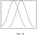
- FIG. 101 shows an overlapping pore size distribution of two woven fabric layers, which resulted in clogging of the downstream woven fabric layer by dirt particles that had initially passed through the upstream woven fabric layer.
- Clogging of the further porous layer 156 by such dirt particles may be addressed by, for example, detachment of the further porous layer 156 from the porous layer 114 to enable cleaning and/or replacement of the further porous layer 156.
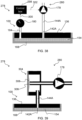
- FIG. 11 schematically depicts an exemplary test arrangement 166 for testing the breaking pressure characteristics of the porous material 168, for example the porous layer 114.
- the porous material 168 is clamped between a clamping member 170 and base plate 172.
- the clamping member 170 delimits holes for bolts 174, which bolts 174 are received in threaded holes in the base plate 172. Turning of the bolts 174 in the appropriate direction enables clamping/releasing of the porous material 168.
- the clamping member 170 is an aluminium ring having a thickness of 10 mm
- the base plate 172 is made of poly (methyl methacrylate) having a thickness of 10 mm.
- the sample of the porous material is a circular disk having a diameter of 140 mm. The sample is secured using eight bolts 174.
- the dirt inlet 142A in this test arrangement 166 is defined by an opening of a transport duct 176 provided in the base plate 172.
- the above-described liquid transporting support structure 154 is provided, in this case in the form of a coarse mesh with a diameter of 80 mm.
- the test arrangement 166 comprises an underpressure generator 178 for generating an underpressure in the dirt inlet 142A, and a pressure sensor 180, e.g. a pressure gauge, arranged to measure the pressure in the dirt inlet 142A.
- a pressure sensor 180 e.g. a pressure gauge
- the pressure sensor 180 in this specific example comprises a pressure gauge in combination with a data acquisition unit (LabQuest ® 2) to enable monitoring of the pressure as a function of time.
- LabQuest ® 2 a data acquisition unit
- the underpressure generator 178 in this specific example is in the form of a peristaltic pump or a syringe pump, e.g. a 250 mL syringe pump.
- the peristaltic pump can provide a pulsed water flow.
- the syringe pump was found to permit more precise measurements than the peristaltic pump.
- the test arrangement 166 also comprises a pressure line filter 182 in the form of a chamber arranged to prevent liquid from entering the pressure sensor line 184 connecting the pressure line filter 182 with the pressure sensor 180. Downstream of the pressure line filter 182 and the pump 178 is a collection reservoir 186 for collecting the liquid pumped through the porous material 168.
- the testing procedure comprises clamping the sample of the porous material 168 between the clamping member 170 and the base plate 172, and then setting the pump 178 to deliver a flow rate of 100 cm 3 /minute.
- the pressure line filter 182 is checked to ensure that it is empty, the pressure gauge of the pressure sensor 180 is zeroed and reconnected before each measurement.
- 25 cm 3 of water is then poured onto the sample of the porous material 168, leaving a layer of water on the porous material having a depth of approximately 4 mm.
- a flushing run is then implemented by starting the pump 178 such that the water is pulled through the sample of the porous material 168.
- the pump 178 is stopped and 25 cm 3 of water is poured onto the sample of the porous material 168, and a measurement run is implemented by triggering the data acquisition unit to start the data acquisition and starting the pump 178.
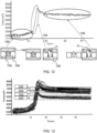
- FIG. 12 A typical graph of underpressure vs time from the data acquisition is provided in FIG. 12 , together with schematic diagrams of the porous material 168.
- the above-described "liquid transport state” 188 is adopted in which the liquid 190, in this example water, is transported through the (pre-wetted) pore 159.
- the recorded "transport pressure” in this case corresponds to the pressure difference required to transport the liquid 190 through the porous material 168 and the coarse mesh liquid transporting support structure 154.
- an intermediate regime 194 is adopted in which almost all of the liquid 190 has been removed from the surface of the sample of the porous material 168, such that most of the pores are in the above-described "fluid block state” in which the surface tension of the (residual) liquid 190 retained in the wetted pore(s) of the porous material 168 prevents air 196 from being transported through the pore 159.
- An ever decreasing number of pores 159 may be in the "liquid transport state” in the intermediate regime 194.
- the "fluid block state” allows a significantly higher underpressure, so during the intermediate regime 194 the underpressure increases relatively rapidly, as shown.
- an end regime 198 is adopted in which all free water has been removed from the surface of the porous material 168, and all the pores 159 are initially in the "fluid block state". Since the pump 178 continues drawing water through the porous material 168, hence increasing the underpressure, this may cause some of the fluid blocks to break such that air 196 is transported through the respective pores 159 in an "air transport state". The associated ingress of air may come to an equilibrium in the end regime 198 in which the applied flow results in an underpressure which causes no more fluid blocks to break. The latter corresponds to the "breaking pressure" of the porous material 168 being investigated.
- the air transport pressure (e.g. 0.18 Pa) and the water transport pressure (e.g. 10. 1 Pa) may both be significantly smaller, e.g. negligible, in comparison to the surface tension-derived pressure difference (e.g. 14600 Pa).
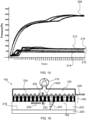
- FIG. 13 provides several pressure vs time graphs for porous materials 168 tested using the above-described test arrangement 166 and test procedure.
- Plots 200 are for a porous material 168 having only a layer of woven fabric;
- plots 202 are for a porous material 168 having the layer of woven fabric and the first further porous layer 156;
- plots 204 are for a porous material 168 having the layer of woven fabric, the first further porous layer 156, and the second further porous layer 158;
- plots 206 are for a porous material 168 having the layer of woven fabric and three further porous layers.
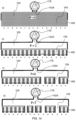
- FIG. 14 schematically depicts the above-described "liquid transport state” 188 in which liquid is being drawn through all of the pores 159 in a), the end of the "liquid transport state” 188 in b), the intermediate regime 194 in c), and the end regime 198 in d).
- the porous material 168 is shown in FIG. 14 covering the dirt inlet(s) 142A, 142B connected to the underpressure generator 178, e.g. pump.
- the porous material 168 has pores 159, e.g. micropores, each having a different breaking pressure.
- the latter is represented in FIG. 14 by the number provided underneath each pore 159. For the sake of simplicity, each number is rounded to a single digit.
- the underpressure generator 178 is a fixed flow-pump, and hence continued operation of the pump may increase the underpressure.
- the underpressure in the dirt inlet 142A behind the porous material 168 may rise to the level, such as "4", of the breaking pressure of the weakest pores 159, the pores' breaking pressure will be exceeded and air may start to be transported therethrough. Since the pressure in the dirt inlet 142A behind the porous material 168 may already be significant when these first pores 159 "break", the air transported by these pores 159 at this point may be significant.
- Step c) in FIG. 14 can thus be regarded as schematically representing the intermediate regime 194.
- pores 159 may be getting blocked while other pores 159 are still transporting liquid from further regions (further away from the dirt inlet(s) 142A), hence creating more underpressure close to the dirt inlet(s) 142A. This can make the underpressure rise relatively slowly until all free liquid is gone. This may all be influenced by the pump rate and, in at least some examples, the properties of the liquid transporting support structure 154, together with the flexibility of all elements, deforming when underpressure is applied.
- the intermediate regime 194 may be a vertical line in FIG. 12 , digitally moving from the "liquid transport state" 188 to the end regime 198.
- Step d) in FIG. 14 can thus be regarded as schematically representing the above-described end regime 198.
- the pressure measured in the test arrangement 166 may define the breaking pressure of the porous material 168.
- Different flow rates, such as 150 cm 3 /minute, have been tested but showing the same breaking pressure, noting that more pores 159 may "break" to compensate for the increased flow.
- the pore size, in other words pore diameter, of the pores 159 of the porous material 168 may be selected in order to balance a relatively high underpressure with a relatively low resistance to transport of liquid through/liquid transport pressure of the porous material 168.
- Smaller pores 159 can increase the underpressure that can be generated in the dirt inlet 142A, e.g. with a relatively low power underpressure generator 178, e.g. pump. Also with the aim of investigating the lower limit of pore size, an investigation was carried out using the above-described test arrangement 166 and test procedure using, as the porous material 168, beer filters specified according the size of particles which they can retain: 0.25 ⁇ m, 3 ⁇ m, 10 ⁇ m and 25 ⁇ m filters were tested.
- plots 208 are for the 0.25 ⁇ m filter; plot 210 is for the 3 ⁇ m filter; plot 212 is for the 10 ⁇ m filter; plot 214 is for the 25 ⁇ m filter; and plot 216 is for a reference microfiber fabric.
- porous size/diameter of the porous material 168 exerts a significant influence on performance.
- the 0.25 ⁇ m filter may lead to the water transport pressure being significantly higher than in the case of the 3 ⁇ m filter.
- the underpressure may rise to about 23000 Pa during water transport.
- the time to reach a dry state may be significantly longer for the 0.25 ⁇ m filter, meaning that it may take significantly more time to transport liquid/water from the surface to be cleaned.
- FIG. 15 appears to show that there is a finite difference between the liquid/water transport pressure and the breaking pressure of the porous material 168.
- Relatively small pores 159 may result in an increase in the breaking pressure, e.g. up to 39000 Pa in the case of the 0.25 ⁇ m filter, but also the water/liquid transport pressure, e.g. 33000 Pa in the case of the 0.25 ⁇ m filter.
- this difference between the water transport pressure and the breaking pressure is similar to that of a reference microfiber fabric (1000 Pa water transport pressure; 7000 Pa breaking pressure).
- Bacteria tends to be characterized by having a relatively small size.
- an Escherichia coli cell which can be regarded as an "average" sized bacterium, is about 2 ⁇ m long and 0.5 ⁇ m in diameter.
- porous materials 168 whose pore size is larger than 2 ⁇ m may permit such bacteria to pass therethrough. In this way, bacteria can be removed from the surface to be cleaned.
- porous material 168 Depending on the porous material 168 selected, up to 99.9% of bacteria can be drawn through the porous material 168, away from the surface to be cleaned.
- such a porous material 168 may have a distribution of pore size/diameter in the above-mentioned 0.25 ⁇ m to 40 ⁇ m range, and an average pore size of 20 to 40 ⁇ m, e.g. about 35 ⁇ m. Since the pore dimensions are significantly larger than the size of bacteria, the bacteria can be pass through the porous material 168, and thus be removed from the surface to be cleaned.
- porous material 168 may be in contact with the surface to be cleaned, and moved across the surface to be cleaned at a certain speed.
- FIG. 16 shows an exemplary cleaner head 100 comprising the dirt inlet 142A covered with the porous material 168 on the surface to be cleaned 218.
- the surface to be cleaned 218 is the surface of a floor 220, and a layer of liquid 222, e.g. water, is present between the surface to be cleaned 218 and the porous material 168.
- the underpressure generator 178 e.g.
- the pump is intended to draw fluid through the pores 159 of the porous material 168 in the direction of the arrows 224.
- the arrow 226 represents the internal underpressure pulling the liquid towards the dirt inlet 142A.
- the arrow 228 represents the velocity of the cleaner head 100.
- FIG. 16 schematically depicts the velocity distribution 234 in the fluid layer 222.
- the arrow 230 represents the fluid shear force on the porous material 168, as generated by the velocity distribution 234 in the fluid layer 222.
- the arrow 232 represents the shear force pulling water towards the floor 220.
- ⁇ P 1125 Pa
- ⁇ P 5000 Pa
- the movement of the cleaner head 100 may create a shear-flow in the layer of liquid 222, creating the shear force 232 acting on liquid present in the porous material 168 which pulls the liquid towards the surface to be cleaned 218.
- the water is also being forced via the underpressure 226 in the direction of the dirt inlet 142A.
- the underpressure may be selected such that the force causing the liquid 222 to move towards the dirt inlet(s) 142A exceeds the shear force 232.
- a further advantage of the liquid pick-up principle described herein may be the lower power consumption, particularly in examples in which the underpressure generator 178 is powered.
- a conventional vacuum cleaner that is capable of picking up water needs to generate significant airspeed and/or brushpower in order to generate enough shear force on water droplets to cause them to enter the vacuum cleaner.
- Typical power consumption values for such vacuum cleaners are several hundred watts.
- the power is 8.3 ⁇ 10 -3 watts.
- the underpressure generator 178 be powered using, for instance, a conventional battery providing a runtime of 28 minutes in a wet cleaning apparatus whose mechanical power consumption is around 50 watts, the runtime in the present case would be 168000 minutes, in other words more than 100 days.
- a powered wet cleaning apparatus having the cleaner head 100 according to the present disclosure may therefore only rarely require recharging of its battery (in examples in which such a battery is included to power the wet cleaning apparatus), and/or may be made more lightweight, due to the minimal battery capacity needed for, for example, a 1 hour runtime. Regarding the latter, it is noted that a battery for a conventional handheld wet cleaning apparatus may weigh around 0.5 kg, and may thus contribute significantly to the overall weight of the wet cleaning apparatus.
- Table 3 provides a mechanical power comparison between a conventional vacuum cleaner and the various states described above in respect of the wet cleaning apparatus according to the present disclosure.
- Table 3 System ⁇ P Pa Flow m 3 /s Mechanical Power W Conventional vacuum cleaner 20000 30 ⁇ 10 -3 600 According to the present disclosure; "fluid transport state” 500 3 ⁇ 10 -6 0.0015 According to the present disclosure; “fluid block state” (only instantaneous, if no pressure sensor is included) 7500 3 ⁇ 10 -6 0.23 According to the present disclosure; "air transport state” 7500 3 ⁇ 10 -6 0.23
- the blocked pores 159 may allow an underpressure to build up inside the wet cleaning apparatus without the need for high power consumption.
- Liquid, e.g. water, that needs to be picked up from the surface to be cleaned may remove the air-water surface locally, and requires only a relatively small underpressure to be sucked into the pores 159.
- the underpressure that has been built up is now capable of picking up the liquid that's on the surface to be cleaned, e.g. floor.
- the present disclosure provides a wet cleaning apparatus comprising the cleaner head member that comprises, e.g. is defined by the porous layer 114, and an underpressure generator 178 for subjecting the porous layer 114 to an underpressure.
- the underpressure generator 178 is configured to provide a pressure difference between an inside of the wet cleaning apparatus and atmospheric pressure for drawing fluid through the porous layer 114, wherein the pressure difference is in a range of 2000 Pa to 15000 Pa, preferably 2000 Pa to 13500 Pa.
- the 2000 Pa lower limit reflects that the cleaner head 100 will typically be moved over a surface to be cleaned, e.g. a floor, and as the speed of the cleaner head 100 over the floor increases, the concomitant drop in static pressure means that liquid is pulled towards the floor. Such behaviour can be approximated by a Bernoulli equation, as described above.
- the 2000 Pa minimum underpressure is correspondingly set according to a minimum typical speed with which a user moves the cleaner head 100 over the surface to be cleaned, thereby to ensure that the underpressure is sufficient to pull liquid into the inside of the wet cleaning apparatus without requiring that the user has to significantly slow or cease movement of the cleaner head 100 over the surface to be cleaned in order for the liquid to be picked up.
- the 15000 Pa, preferably 13500 Pa, upper limit is defined for the purpose of ensuring that liquid transport through the porous material 168 is sufficiently rapid.
- the pressure difference is 5000 Pa to 9000 Pa, and most preferably 7000 Pa to 9000 Pa. These ranges may reflect particularly enhanced liquid pick-up observed during movement of the cleaner head 100, combined with relatively low flow resistance through the porous material 168.
- the pressure difference can be directly and positively verified in a given wet cleaning apparatus by, for example, drilling a hole in a tube of the wet cleaning apparatus which is fluidly connected with the dirt inlet(s) 142A, 142B and using the hole to couple to a pneumatic pressure sensor itself having a tube with a membrane covering an end thereof; the sensor being thus connected using an airtight connection.
- the sensor may be arranged to avoid disturbing the flow, hence the skilled person will arrange the sensor to avoid, for instance, creating a bypass flow. No flow may be towards or from the sensor: only pressure is transmitted. In this way, the flow of the appliance may never be compromised (hence may remain at the set level in spite of the sensor installation).
- the pressure sensor is connected between the porous material 168 and the underpressure generator 178 and as close to the porous material 168 as possible, to minimise the influence of other factors, such as flow resistance etc., on the sensed pressure difference.
- the sensing element/membrane of the pressure sensor/gauge is ideally arranged/positioned in the pressure sensor so that the sensing element can be placed directly (without the requirement for connecting tubes) in the tube, or in the cavity 150 behind the porous material 168.
- membrane pressure gauge By positioning the membrane of the pressure sensor, in other words membrane pressure gauge, with the membrane positioned at, in other words in line with, the wall of the tube (or exposed to the cavity 150), measurement errors may be minimized, as will be appreciated by a person skilled in the art.
- air bubbles inside narrow tubes may generate resistance (capillary/surface tension effects), and hence may influence the measurement.
- care is also to be taken that air bubbles (water-air surfaces) do not unduly influence the pressure difference measurement.
- a column of water present between the pressure sensor and the porous material 168 should be deducted from the measurement result (if such a column of water is present during the measurement), to compensate for the static pressure generated by the column of water.
- the pressure sensor is arranged as described above, it may be ascertained that maintenance of the underpressure is due to the porous material 168 and not some other element, such as a valve. Any such element that influences the underpressure that is presented to the porous material 168 should be rendered inoperable for the purpose of performing the measurement.
- Component(s) that dispense cleaning liquid (should the wet cleaning apparatus be configured to deliver cleaning liquid) is/are disengaged when performing the pressure difference measurement.
- the wet cleaning apparatus is turned on (in the desired setting), so that the pick-up system comprising the underpressure generator 178 is activated. Recording of data from the pressure sensor is started.
- the pick-up area of the cleaner head 100 is suspended in a layer of water, at max. 5 mm depth.
- the pick-up area is then lifted from the water without tilting it in any way (so that the cleaner head 100 remains in a cleaning position, as if it were positioned to clean the floor), so that the water is no longer touching the porous material 168.
- "free water” will be removed from the porous material 168, all pores will go into their "blocked state", and the breaking pressure is determinable.
- the measurement result will resemble the graph shown in FIG. 12 , once again noting that an equilibrium is established in the end regime 198 in which the applied flow results in an underpressure which causes no more fluid blocks to break.
- the breaking pressure obtained from this measurement result is the "pressure difference between the inside of the wet cleaning apparatus and atmospheric pressure for drawing fluid through the porous material 168 and into the at least one dirt inlet 142A, 142B.” It is verified from the measurement result whether or not the 2000 Pa to 15000 Pa range or the 2000 Pa to 13500 range is satisfied.
- the porous material 168 may be arranged to contact liquid on the surface to be cleaned, as previously described.
- the porous material 168 may be defined from an exterior surface of the porous material 168 exposable to liquid on a surface to be cleaned to an interior surface of the porous material 168 exposed to the at least one dirt inlet.
- ASTM F316 - 03, 2019, Test A provides a bubble point pressure measurement. Whilst this standard method was developed for nonfibrous membrane filters, the procedure can be replicated for the porous material 168, e.g. the porous layer 114 and the further porous layer(s) 156, 158, according to the present disclosure.
- the bubble point test for determining the limiting pore diameter is, in summary, performed by prewetting the sample of the porous material 168, increasing the pressure of gas upstream of the porous material 168 at a predetermined rate, and watching for gas bubbles downstream to indicate the passage of gas through the maximum diameter pores of the porous material 168.
- the porous material 168 may be approximated in some cases or, in the case of the porous layer 114, be regarded as having discrete pores extending from one side of the porous material 168 to the other, similarly to capillary tubes.
- the bubble point test is based on the principle that a wetting liquid is held in these capillary pores by capillary attraction and surface tension, and the minimum pressure required to force liquid from these pores is a function of pore diameter. The pressure at which a steady stream of bubbles appears in this test is termed the "bubble point pressure".
- ASTM F316 - 03, 2019, Test A is based on an approximation of the pores as capillary pores having circular cross-sections, and hence the limiting pore diameter should be regarded as merely an empirical estimate of the maximum pore diameter based on this premise.
- the porous layer 114 has a limiting pore diameter, as measured using ASTM F316 - 03, 2019, Test A, equal to or less than 105 ⁇ m.
- the 105 ⁇ m upper limit for the limiting pore diameter equivalent to a minimum bubble point pressure of 2000 Pa, may assist to ensure that sufficient underpressure is maintainable by the porous layer.
- the limiting pore diameter of the porous layer 114 as measured using ASTM F316 - 03, 2019, Test A is at least 6 ⁇ m, preferably at least 8 ⁇ m, most preferably at least 11 ⁇ m.
- a limiting pore diameter equal to or greater than 6 ⁇ m may assist to maintain a relatively large underpressure whilst ensuring that pores still enable efficient liquid transport therethrough.
- the latter may also be assisted by minimizing the thickness of the porous layer 114, for example to less than 200 ⁇ m, preferably less than 150 ⁇ m.
- the physical pore size of pores of the porous layer 114 may be larger than that of pores of the further porous layer 156, e.g. woven fabric layer(s), e.g. around 3 ⁇ m.
- the limiting pore diameter of the porous layer 114 as measured using ASTM F316 - 03, 2019, Test A is 11 to 15 ⁇ m.
- the thickness of the porous layer 114 is less than 200 ⁇ m, preferably less than 100 ⁇ m. Such a maximum thickness may contribute to minimizing of flow resistance through the porous layer 114.
- the thickness of the porous layer 114 can be determined by using a precision gauge and two ground metal plates (with the upper plate by which the normal pressure is applied being 70 mm x 30 mm, and the lower plate on which the sample of the porous material is supported having a larger area than the 70 mm x 30 mm surface of the upper plate for ease of alignment) for receiving the porous layer 114 therebetween.
- the arrangement is configured to apply a pressure normal to the sample of the porous layer 114 (70 mm x 30 mm) of 864.2 N/m 2 .
- Table 5 Metal plate parameters Length 70 mm Area of sample 2100 mm 2 Width 30 mm Total mass 185 g mass 85 g Total force 1.81 N Fn (gauge force) 100 g Pressure 864.2 N/m 2
- the further porous layer 156 may comprise one or more woven fabric layers.
- the further porous layer 156 e.g. woven fabric layer(s)
- a limiting pore diameter of the further porous layer 156 e.g. woven fabric layer(s), as measured using ASTM F316 - 03, 2019, Test A equal to or greater than 15 ⁇ m may assist to maintain a relatively large underpressure whilst ensuring that pores are sufficiently large for efficient liquid transport through the further porous layer 156.
- a bubble point pressure of the further porous layer 156 as measured using ASTM F316 - 03, 2019, Test A may be equal to or less than 13500 Pa.
- a limiting pore diameter of the further porous layer 156 as measured using ASTM F316 - 03, 2019, Test A is equal to or less than 105 ⁇ m. This upper limit for the limiting pore diameter assists to ensure that sufficient underpressure is maintainable by the further porous layer 156.
- a bubble point pressure of the further porous layer 156 as measured using ASTM F316 - 03, 2019, Test A may be equal to or greater than 2000 Pa.
- the bubble point pressure of the further porous layer is 7000 Pa to 9000 Pa.
- the further porous material 156 comprising a porous woven fabric, and most preferably a woven microfiber fabric.
- microfiber fabric as used herein may refer to a fabric formed of synthetic fibers, with the fabric being formed of threads whose titre is less than 1 decitex.
- microfiber fabrics can comprise, for example, polyester fibers, polyamide fibers, and combinations of polyester and polyamide fibers.
- the microfiber fabric may, for example, be a microfiber chamois.
- Such a porous woven fabric, and in particular such a woven microfiber fabric, can be configured, in particular via the tightness of its weave, to satisfy the above ranges for the limiting pore diameter.
- Table 6 Specifications of a particularly suitable woven fabric are provided in Table 6 as an illustrative non-limiting example.
- the underpressure generator 178 is configured to provide a flow rate through the porous material 168, e.g. through the porous layer 114, which is less than or equal to 2000 cm 3 /minute.
- Such a flow rate may be significantly lower than for the conventional wet vacuum cleaners mentioned above. Since power is equal to flow rate multiplied by the pressure difference, by combining this maximum 2000 cm 3 /minute flow rate with the above-described maximum 15000 Pa pressure difference as a maximum power consumption scenario, the power consumption of the wet cleaning apparatus may be minimised. Referring to Table 3 above, this may enable the wet cleaning apparatus to made relatively compact, e.g. using a smaller battery, and/or to have a relatively long runtime.
- the underpressure generator 178 may be configured to provide a flow rate through the porous material 168, e.g. through the porous layer 114, which is equal to or greater than 15 cm 3 /minute. This may contribute to the pick-up of liquid from the surface to be cleaned being sufficiently rapid.
- the 15 cm 3 /minute lower limit may, in some embodiments, be set to equal or exceed a flow rate of a cleaning liquid from cleaning liquid outlet(s) 104 also included in the cleaner head 100.
- the underpressure generator 178 is configured to provide a flow rate through the porous material 168, e.g. through the porous layer 114, which is equal to or greater than 40 cm 3 /minute. As well as contributing to efficient liquid pick-up, this 40 cm 3 /minute may, in some embodiments, be set to equal or exceed a flow rate of a cleaning liquid from cleaning liquid outlet(s) also included in the cleaner head 100, with the minimum cleaning liquid flow rate being set to ensure plentiful supply of the cleaning liquid to the surface to be cleaned.
- the underpressure generator 178 may be configured to provide a flow rate through the porous material 168, e.g. through the porous layer 114, in the range of 80 to 750 cm 3 /minute, more preferably 100 to 300 cm 3 /minute, and most preferably 150 to 300 cm 3 /minute.
- a flow rate may capitalise on the underpressure-maintaining capability of the porous material 168, and may ensure sufficient liquid pick-up whilst limiting energy consumption.
- a fluid transport pressure at 200 cm 3 /minute flow through the porous material 168, e.g. through the porous layer 114, is less than 0.25 multiplied by the bubble point pressure as determined by ASTM F316 - 03, 2019, Test A.
- the wet cleaning apparatus may operate with the breaking pressure being higher than the transport flow pressure, but for the purpose of enabling pick-up at higher speed, the breaking pressure may be at least twice the transport flow pressure.
- the cleaner head 100 may deliver cleaning liquid at a flow rate of 40 cm 3 /minute. With a flow rate through the porous material 168 of 85% of this cleaning liquid flow rate on a smooth surface to be cleaned, i.e. a pick-up rate of 34 cm 3 /minute, the pick-up rate is comparable to the 31 cm 3 /minute estimated above for sample number 24.
- FIGs. 17 to 23 schematically depict examples of how the porous material 168, e.g. the porous layer 114, may be mounted in the cleaner head 100 or in a cleaner head member for such a cleaner head 100.
- the cleaner head 100 or cleaner head member comprises a support member 236, for example a rigid support member 236, for supporting the porous material 168, e.g. the porous layer 114.
- the support member 236 can be formed of any suitable material, such as an engineering thermoplastic.
- the cleaner head 100 or the cleaner head member comprises a pliable material 238 on which the porous material 168 is arranged.
- Deformation, e.g. resilient deformation, of such a pliable material 238 may lessen the risk of damage to the porous material 168, e.g. the porous layer 114, should, for example, a relatively hard protrusion be present on the surface to be cleaned 218 which comes into contact with the porous material 168.
- the pliable material 238 may assist the porous material 168, e.g. the porous layer 114, to follow any contours of the surface to be cleaned 218.
- the pliable material 238 can, for instance, be or comprise an elastomeric material, e.g. silicone rubber.
- Other pliable material such as a polydiene, e.g. polybutadiene, a thermoplastic elastomer, and so on, can also be contemplated for inclusion in, or defining of, the pliable material 238.
- silicone rubber and ethylene-vinyl acetate in other words a copolymer of ethylene and vinyl acetate, for the pliable material 238.
- the pliable material 238 is formed from a closed cell foam material, for example an ethylene-vinyl acetate closed cell foam material.
- pliability may be provided, at least in part, by the foam structure, with the closed cell structure of the foam providing the a liquid barrier.
- the pliable material 238 can be less than 50 Shore A, preferably less than 20 Shore A, most preferably less than 10 Shore A.
- the pliable material 238 is 4 Shore A silicone rubber.
- the pliable material 238 can be provided between the support member 236 and the porous material 168, e.g. between the support member 236 and the porous layer 114. An example of this is shown in FIG. 17 .
- the porous layer 114 may be affixed, e.g. adhered, to the support member 236.
- the protruding element may comprise the pliable material 238, as will be described in more detail herein below.
- the impermeable portion 146 is in the form of a polymer, e.g. thermoplastic, film, with the seal 152 being provided between the polymer film and the porous layer 114 included in the porous material 168.
- the liquid transporting support structure 154 included in this particular example is in the form of a coarse mesh or a stack of coarse mesh layers.
- the impermeable portion 146 is defined by impermeable sealing portion(s), e.g. pieces of polymer film, extending from the pliable material 238 to the porous layer 114 of the porous material 168. In this case, there may be no need for a polymer film to extend laterally over the internal surface of the porous layer 114.
- the pliable material 238 comprises the impermeable portion 146 sealed onto the porous layer 114 of the porous material 168.
- the above-described polymer film and pieces of polymer film are therefore obviated in this example, and can be omitted. In this manner, the number of components in the cleaner head 100 may be reduced, thereby facilitating manufacture.
- the liquid transporting support structure 154 is at least partly, or entirely, provided by a surface pattern on and/or in the surface of the pliable material 238 facing the porous layer 114 of the porous material 168. Replacing the coarse mesh(es) with the surface pattern on the surface of the pliable material 238 may assist in terms of reducing the number of components in the cleaner head 100.
- the example shown in FIG. 19 corresponds to that depicted in FIG. 18 .
- the support member 236 comprises the impermeable portion 146 sealed against the porous layer 114 of the porous material 168.
- the seal present between the support member 236 and the porous material 168 is provided by protruding portions of the support member 236 which seal against the porous material 168.
- the above-described polymer film is not necessary in this example because the seal can be created using a direct connection between the porous layer 114 and the support member 236.
- the example shown in FIG. 20 corresponds to that depicted in FIG. 17 .
- FIG. 21 corresponds to that shown in FIG. 20 other than the liquid transporting support structure 154 being at least partly, or entirely, provided by a surface pattern on and/or in the surface of the pliable material 238 facing the porous layer 114 of the porous material 168.
- FIG. 22 corresponds to that shown in FIG. 18 other than the pliable material 238 being arranged within the cavity 150 provided between a polymer film as the impermeable portion 146 and the porous layer 114 of the porous material 168.
- FIG. 23 corresponds to that shown in FIG. 22 other than the liquid transporting support structure 154 being at least partly, or entirely, provided by a surface pattern on and/or in the surface of the pliable material 238 facing the porous layer 114 of the porous material 168.
- the above-described liquid pick-up region PR of the porous layer 114 (delimited by sealing attachment of the porous layer 114 around the, e.g. each of the, at least one dirt inlet 142A, 142B) may be arranged relative to each of the at least one cleaning liquid outlet 104 such as to allow the cleaning liquid to bypass the liquid pick-up region PR to reach, or at least be directed towards, the surface to be cleaned 218.
- Such arrangement of the liquid pick-up region PR relative to each of the cleaning liquid outlet(s) 104 can be achieved in any suitable manner.
- each of the cleaning liquid outlets 104 are arranged in one or more dispensing parts which are spatially separated from the porous layer 114.
- the cleaning liquid outlet(s) 104 By arranging the cleaning liquid outlet(s) 104 in such a separate dispensing part or parts, the cleaning liquid can be delivered towards the surface to be cleaned 218, in the direction of the arrows 240 in FIG. 24 , without initially contacting the porous layer 114.
- the dispensing parts correspond to the above-described cleaning liquid distribution strips 108, 124.
- gaps 242 e.g. air gaps 242, provided between the porous layer 114 and the cleaning liquid distribution strips 108, 124.
- the porous material 168 comprises the above-described one or more further porous layers 156.
- a cleaning material 244 may comprise the one or more further porous layers 156, e.g. with detachment of the cleaning material 244 separating the one or more further porous layers 156 from the porous layer 114.
- the cleaning material 244 is made solely from fabric, e.g. with the cleaning material 244 only being required to be in fluid connection with the wet cleaning apparatus, without special seals/connections being needed. Attachment of the cleaning material 244 to the wet cleaning apparatus, e.g. to the cleaner head 100, can be implemented using relatively simple fastening, e.g. a hooks-loops fastening only.
- the cleaning material 244 e.g. mop
- the cleaning material 244 may be straightforwardly washable, e.g. in a washing machine, and may be inexpensive to produce.
- the porous layer 114 of the cleaner head member may be primarily responsible for maintaining the requisite underpressure, hence may be sealingly attached around the dirt inlet(s) 142A, 142B, as previously described. Moreover, the porous layer 114 may be free from worn areas and relatively large holes in order for the underpressure to be maintainable. On the other hand, the cleaning material 244/further porous layer 156 may not be required to hold the underpressure, and may instead only be required to create a capillary connection between the surface to be cleaned and the porous layer 114.
- the pick-up functionality may not operate in the vicinity of such holes but it may where the further porous layer 156 is in contact with the porous layer 114 and the surface to be cleaned, since the further porous layer 156 need only provide a fluid connection.
- the cleaning material 244 comprises the above-described cleaning liquid applicator material 126, 128.
- the one or more further porous layers 156 can be straightforwardly replaced at the same time as replacing the cleaning liquid applicator material 126, 128.
- the cleaning liquid applicator material 126, 128 can be attached, e.g. adhered, to the one or more further porous layers 156 in the cleaning material 244.
- the cleaning liquid applicator material 126, 128 comprises the above-described first and second applicator portions 126, 128, with a first attachment 246A connecting the one or more further porous layers 156 to the first applicator portion 126, and a second attachment 246B connecting the one or more further porous layers 156 to the second applicator portion 128.
- the present disclosure provides a surface cleaning assembly comprising the porous layer 114-comprising cleaner head member 248 according to any of the embodiments described herein, and a cleaning material 244 for contacting a surface to be cleaned, the cleaning material comprising the further porous layer 156 for arranging on the porous layer 114.
- the cleaner head 100 comprises a support for supporting the porous layer 114 included in the cleaner head member 248.
- the cleaner head member 248 may be attachable to and/or detachable from the cleaner head 100, which may for example involve the porous layer 114 being joined to and/or separated from the support included in the cleaner head 100.
- the cleaner head member 248 may comprise, in addition to the porous layer 114, the above-described impermeable portion 146, e.g. comprising or in the form of a polymer film, with the at least one dirt inlet 142A being defined by an aperture or apertures in the impermeable portion 146.
- the cleaner head member 248 further comprises the above-described liquid transporting support structure 154.
- liquid transporting support structure 154 may be provided in the cavity 150 between the porous layer 114 and the impermeable portion 146.
- the cleaning material 244 may, for instance, be detachable independently of the cleaner head member 248, and the cleaner head member 248 may be detachable independently of the cleaning material 244.
- the cleaner head member 248 further comprises the cleaning liquid applicator material 126, 128.
- the cleaning liquid applicator material 126, 128 may be attached, e.g. adhered, to the impermeable portion 146.
- the cleaning liquid applicator material 126, 128 comprises the above-described first and second applicator portions 126, 128, with a first connection 250A connecting a first side of the impermeable portion 146 to the first applicator portion 126, and a second connection 250B connecting a second side of the impermeable portion 146 to the second applicator portion 128.
- FIG. 28 schematically depicts an exemplary cleaner head 100 comprising the cleaner head member 248, which cleaner head member 248 does not including the cleaning liquid applicator material 126, 128.
- the cleaning liquid applicator material 126, 128 is nonetheless detachable, with each of the first and second applicator portions 126, 128 in this example being detachable from the cleaning liquid outlets 104 independently of each other and independently of the cleaner head member 248.
- the cleaner head member 248 comprises the porous layer 114.
- the cleaner head member 248 may be suitable for attaching to a wet cleaning apparatus having an underpressure generator 178.
- one or more dirt inlet(s) 142A, 142B is or are defined in the cleaner head member 248, with the porous layer 114 covering the one or more dirt inlet(s) 142A, 142B.
- the dirt inlet(s) may fluidly connect the underpressure generator 178 with the pores 159 of the porous layer 114.
- a liquid pick-up region PR of the porous layer 114 may be delimited by sealing attachment of the porous layer 114 around the at least one dirt inlet 142A, 142B.
- the sealing attachment of the porous layer 114 around the dirt inlet(s) may assist to maintain an underpressure in the dirt inlet(s) 142A, 142B with or without the flow being applied by the underpressure generator 178 included in the wet cleaning apparatus.
- the sealing attachment can be implemented in any suitable manner, such as by gluing or welding the porous layer 114 around the, e.g. each of, the at least one dirt inlet 142A, 142B, for example gluing and/or welding the porous layer 114 around one or more tubes whose opening(s) define the dirt inlet(s) 142A, 142B.
- Such a cleaner head member 248 may enable replacement of the porous layer 114 without requiring re-sealing of the porous layer 114 to the dirt inlet(s) 142A, 142B.
- the cleaner head member 248 comprises an impermeable portion 146, and the at least one dirt inlet 142A, 142B is defined by an aperture or apertures provided in the impermeable portion 146 and/or between the impermeable portion 146 and the porous layer 114.
- Such a cleaner head member 248 may enable replacement of the porous layer 114 without requiring re-sealing of the impermeable portion 146 to the porous layer 114.
- the at least one dirt inlet 142A, 142B is exposed to a cavity 150 between the porous layer 114 and the impermeable portion 146, with a liquid transporting support structure 154 being arranged in the cavity 150, and providing one or more flow paths in the liquid pick-up region PR between the porous layer 114 and the at least one dirt inlet 142A, 142B.
- the wet cleaning apparatus e.g. the cleaner head 100 included in the wet cleaning apparatus, may comprise at least one cleaning liquid outlet 104 through which cleaning liquid is deliverable, as previously described.
- the liquid pick-up region PR may be arranged relative to each of the at least one cleaning liquid outlet 104 such that the liquid pick-up region PR is bypassed by the cleaning liquid delivered towards the surface to be cleaned 218.
- FIG. 29 schematically depicts an exemplary cleaner head 100 comprising the cleaning material 244, which cleaning material 244 consists in this example of the one or more further porous layers 156. Moreover, in this non-limiting example, each of the first and second applicator portions 126, 128 in this example is detachable from the cleaning liquid outlets 104 independently of each other and independently of the cleaning material 244.
- FIG. 30 shows an exemplary cleaner head 100 in which the porous material, in this case the porous layer 114, contacts the cleaning liquid applicator fabric 126, 128.
- this configuration may assist to prevent an excess of cleaning liquid building up in the cleaning liquid applicator material 126, 128, and thus may assist to minimise excessive wetting of the surface to be cleaned 218, for instance by dripping of the cleaning liquid from the cleaning liquid applicator material 126, 128 onto the surface to be cleaned 218.
- enhanced control over the wetness of the cleaning liquid applicator material 126, 128 may be achieved due to the edge portion 134 of the porous layer 114 abutting an opposing edge portion 136 of the cleaning liquid applicator material 126, 128.
- the cleaning liquid applicator material 126, 128 comprises the first applicator portion 126 and the second applicator portion 128, such that the opposing edge portion 136 of the cleaning liquid applicator material is included in the first applicator portion 126, as shown.
- the further edge portion 138 of the porous layer 114 abuts a further opposing edge portion 140 of the second applicator portion 128.
- the liquid pick-up region PR of the porous layer 114 (delimited by sealing attachment of the porous layer 114 around the, e.g. each of the, at least one dirt inlet 142A, 142B) is nonetheless arranged relative to each of the cleaning liquid outlets 104 in the example shown in FIG. 30 such as to allow the cleaning liquid to bypass the liquid pick-up region PR.
- the cleaning liquid outlets 104 in this example are arranged in dispensing parts, in this example in the form of cleaning liquid distribution strips 108, 124, which are spatially separated from the porous layer 114. The latter is reflected by the gaps 242, e.g. air gaps 242, provided between the porous layer 114 and the dispensing parts 108, 124.
- the cleaner head 100 comprises the portion 120 for facing the surface to be cleaned 218, with a protruding element 252 being mounted adjacent the portion 120.
- the protruding element 252 is thus an element mounted separately with respect to the portion 120.
- the protruding element 252 protrudes from the cleaner head 100 in the direction of the surface to be cleaned 218.
- the cleaner head 100 can be rocked on the protruding element 252 in a first direction to cause the portion 120 to contact the surface to be cleaned, and rocked on the protruding element 252 in a second direction opposite to the first direction to cause the portion 120 to be separated from the surface to be cleaned 218, as previously explained.
- the cleaner head 100 comprises the support member 236, e.g. a rigid support member 236, and the protruding element 252 is mounted via attachment to the support member 236.
- the cleaner head 100 can be attached or may be attachable to a suitable handle (not visible) to assist moving the cleaner head 100.
- the cleaner head 100 may comprise a coupling point 254 to which such a handle may be coupled, e.g. pivotably coupled.
- movement of the cleaner head 100 over the surface to be cleaned 218 by application of a force, F move may not be without resistance.
- the weight of the cleaner head 100, F gravity , and/or the user pressing the cleaner head 100 towards the surface to be cleaned 218 may create a force, F n , normal to the surface to be cleaned 218.
- the cleaner head 100 may be wet, and therefore may operate in a viscous friction regime and a dry regime; the former resulting in a viscous friction force, F v , and the latter resulting in coulombic friction, F c , governed by the normal force, F n , and the coefficient of friction, f.
- the resulting resistance force, F r is approximated in the following equation.
- ⁇ the dynamic viscosity in Pa ⁇ s
- A the area of contact in m 2
- u the velocity in m/s
- y the thickness of liquid layer in m.
- the relatively large contact area, A that is needed for effective liquid pick-up on uneven surfaces to be cleaned 218, may result in a relatively high resistance force F r , especially on relatively flat/smooth surfaces to be cleaned 218.
- the protruding element 252 comprises the porous material 168, e.g. the porous layer 114. Resistance to motion of the cleaner head 100 across the surface to be cleaned may therefore be lessened due to the limited area of contact A between the porous material 168, e.g. the porous layer 114, and the surface to be cleaned 218.
- the liquid pick-up region PR of the porous layer 114 is included in the protruding element 252 and terminates between the protruding element 252 and the portion 120. In this manner, the area of the porous layer 114 to which suction is applied is confined to the protruding element 252, thereby assisting to alleviate resistance to motion.
- the at least one dirt inlet 142A, 142B may be defined in the protruding element 252.
- suction may be applied to the part of the cleaner head 100, in other words the protruding element 252, whose contact with the surface to be cleaned 218 is lessened, e.g. due to its rocking function.
- the protruding element 252 may be mounted between the portion 120 and the further portion 122. In this way, the cleaner head 100 can be rocked forwards on the protruding element 252 to cause the portion 120 to contact the surface to be cleaned 218, as shown in FIG. 31 , and backwards to cause the further portion 122 to contact the surface to be cleaned 218.
- the liquid pick-up region PR of the porous layer 114 may extend between the portion 120 and the further portion 122, and terminate between the protruding element 252 and the portion 120, and between the protruding element 252 and the further portion 122.
- the abutting opposing edge portions 134, 136 of the porous material 168 and the cleaning liquid applicator material 126, 128 are positioned between the protruding element 252 and the portion 120.
- excess cleaning liquid caused to be squeezed from the cleaning liquid applicator material 126, 128 between the protruding element 252 and the cleaning liquid applicator material 126, 128, e.g. by rocking of the cleaner head 100 may be efficiently transported into the dirt inlet(s) 142A, 142B via the porous material 168.
- the portion 120 shown in FIG. 31 comprises the first applicator portion 126
- the further portion 122 comprises the second applicator portion 128.
- the abutting opposing edge portions 134, 136 of the porous material 168 and the first applicator portion 126 in this example are positioned between the protruding element 252 and the portion 120
- the abutting opposing further edge portions 138, 140 of the porous material 168 and the second applicator portion 128 are positioned between the protruding element 252 and the further portion 122.
- the protruding element 252 has a curved surface arranged to contact the surface to be cleaned 218.
- Such a curved, e.g. rounded, surface of the protruding element 252 may further assist to minimise the area of contact of the protruding element 252 with the surface to be cleaned 218, and thereby assist to minimise resistance to motion of the cleaner head 100 across the surface to be cleaned 218.
- the curved surface of the protruding element 252 may, for example, curve between the portion 120 and further portion 122, as shown in FIG. 31 .
- the protruding element 252 comprises the above-described pliable material 238 on which the porous material 168 is arranged.
- the pliable material 238 can, for instance, be or comprise silicone rubber and/or have a hardness less than 50 Shore A, preferably less than 20 Shore A, most preferably less than 10 Shore A.
- the pliable material 238 may be arranged between the support member 236, e.g. the rigid support member 236, and the porous material 168.
- Such a pliable material 238 may lessen the risk of damage to the porous material 168 should, for example, a relatively hard protrusion be present on the surface to be cleaned 218 which comes into contact with the porous material 168.
- the pliable material 238 may assist the porous material 168 to follow any contours of the surface to be cleaned 218.
- the protruding element 252 may be resiliently mounted adjacent the portion 120.
- the protruding element 252 may be spring-mounted to the support member 236. This may assist the porous material 168 to follow any contours of the surface to be cleaned 218, thereby facilitating liquid pick-up.
- the curvature of a curved surface of the pliable material 238, e.g. arcing between the portion 120 and the further portion 122, may be followed by the porous material 168 to provide the curved surface of the protruding element 252.
- the protruding element 252 may further comprise the above-described impermeable portion 146 comprising or in the form of a polymer film sealed onto the porous layer 114 and around the dirt inlets 142A, 142B.
- the underpressure present behind the porous material 168 during use of the cleaner head 100 may not be present in the pliable material 238, but rather is contained within the sealed cavity 150 between the porous layer 114 and the impermeable portion 146. This may assist to ensure that the pliable material 238 is substantially unaffected by the underpressure, particularly in examples in which the pliable material 238 is itself porous and may therefore otherwise be prone to compaction due to the underpressure.
- the pliable material 238 is itself non-porous or has a closed cell foam structure, such that the pliable material 238 can be included in the impermeable portion 146 sealed onto the porous layer 114 of the porous material 168, e.g. as described above in relation to FIG. 18 .
- the above-described liquid transporting support structure 154 is also provided between the porous material 168, in particular the porous layer 114, and the impermeable portion 146.
- the liquid transporting support structure 154 can be defined by or include, for example, one or more coarse mesh layers and/or a surface pattern on and/or in the surface, e.g. curved surface, of the pliable material 238.
- the protruding element 252 can comprise a liquid transporting support structure 154, e.g. arranged between the porous layer 114 and the at least one dirt inlet 142A, 142B.
- the porous material 168 may be arranged on the pliable material 238, e.g. on a curved surface of the pliable material 238, in any suitable manner.
- FIGs. 32A and 32B schematically depict an example of sealing attachment of the porous layer 114 around the dirt inlets 142A, 142B to define the liquid pick-up region PR. Further evident in FIGs. 32A and 32B are the impermeable portion 146, in this case in the form of a polymer film, and the liquid transporting support structure 154, in this case in the form of a coarse mesh or a plurality of stacked coarse mesh layers.
- the porous material 168 in this example comprises, or is defined by, the porous layer 114 and the further porous layers 156, 158.
- a laminate comprises the further porous layers 156, 158, the porous layer 114, the liquid transporting support structure 154, and the impermeable portion 146, with the tubes 144A, 144B providing the dirt inlets 142A, 142B being partially trapped between the impermeable portion 146 and the porous layer 114.
- the impermeable portion 146, the porous layer 114, and the further porous layers 156, 158 extend beyond the liquid transporting support layer 154 in the direction of the tubes 144A, 144B.
- the seal 152 in this case a heat seal, also extends beyond the liquid transporting support layer 154 in the direction of the tubes 144A, 144B.
- the seal 152 i.e. an airtight seal, is provided between the porous layer 114 and the impermeable portion 146 by introducing clay in the area between the porous layer 114 and the impermeable portion 146 through which the tubes 144A, 144B are led.
- a piece of tape is then wound around the porous layer 114, impermeable portion 146, tubes 144A, 144B and the clay, to envelope the clay, to avoid it sticking to another obj ect.
- This laminate may be sufficiently pliable to be arranged on a curved surface of, for instance, the pliable material 238.
- the laminate may, for instance, be provided with a suitable fastener or fasteners 256A-D, in this case in the form of Velcro ® strips, for securing the laminate in the cleaner head 100.
- FIGs. 33A and 33B a laminate similar to that described above in relation to FIGs. 32A and 32B , comprising the porous layer 114 and a first further porous layer 156 is arranged on the curved surface 258 of the pliable material 238, and secured to the support member 236 via the fastener(s) 256A-D, e.g. Velcro ® .
- the protruding element 252 in this example comprises the pliable material 238 and the porous layers 114, 156.
- the protruding element 252 itself comprises a curved surface arranged to contact the surface to be cleaned 218.
- the protruding element 252 is mounted adjacent the portion 120 (and in particular between the portion 120 and the further portion 122 in this example) by the pliable material 238 being attached to the support member 236 of the cleaner head 100.
- this attachment is achieved at least partly by the pliable material 238 comprising a projection 260 which is received within and engages a slot 262 defined in the support member 236.
- the projection 260 may, for instance, be a push-fit in the slot 262.
- FIG. 33A shows deformation of the cleaning liquid applicator material 126, 128 to bring at least part of the cleaning liquid applicator material 126, 128 into contact with the porous material. In this way, some of the cleaning liquid can be transferred from the cleaning liquid applicator material 126, 128 to the porous material in a particularly controlled manner.
- the cleaning liquid applicator material 126, 128 comprises tufts formed from fibers, and a backing layer (not visible) supporting the tufts. As shown, such tufts may be deformable to contact the porous material, e.g. upon contact with the surface to be cleaned and/or upon being wetted by liquid, e.g. water.
- a wet cleaning apparatus comprises the cleaner head 100, and an underpressure generator 178 (not visible in FIGs. 33A and 33B ) fluidly connected to the at least one dirt inlet 142A, 142B.
- This fluid connection may be made via the tubes 144A, 144B, which, in this particular non-limiting example, extend to a single tube leading to the underpressure generator at a bifurcation point 266.
- the underpressure generator 178 may, for example, be or comprise a pump, such as a positive displacement pump (technical benefits of the latter being described in more detail herein below). Any suitable pump can be used, provided that the pump is capable of withstanding the operating pressures selected for the wet cleaning apparatus, e.g. about 5000 Pa (see Table 2 above).
- the underpressure generator 178 is configured to supply suction by providing a flow in the range of 40 to 2000 cm 3 /minute, more preferably 80 to 750 cm 3 /minute, and most preferably 100 to 300 cm 3 /minute.
- Such a flow i.e. flow rate, may capitalise on the underpressure-maintaining capability of the porous material 168, and may ensure sufficient liquid pick-up whilst limiting energy consumption.
- the wet cleaning apparatus may also include a dirty liquid collection tank (not visible in FIGs. 33A and 33B ).
- the underpressure generator may be arranged to draw liquid from the at least one dirt inlet 142A, 142B to the dirty liquid collection tank.
- the dirty liquid collection tank can be arranged in any suitable manner relative to, e.g. upstream or downstream of, the underpressure generator 178.
- the wet cleaning apparatus comprising the cleaner head 100 comprises a cleaning liquid supply (not visible in FIGs. 33A and 33B ) for supplying cleaning liquid to the cleaner head 100 for delivery towards the surface to be cleaned by the at least one cleaning liquid outlet(s) 104.
- a cleaning liquid supply may, for example, comprise a cleaning liquid reservoir and a delivery arrangement, e.g. a delivery arrangement comprising a pump, for transporting the cleaning liquid to and through the at least one cleaning liquid outlet 104.
- the cleaning liquid supply and the at least one cleaning liquid outlet 104 may be configured to provide a continuous delivery of the cleaning liquid towards the surface to be cleaned 218.
- the cleaning liquid supply and the underpressure generator 178 may, for instance, be configured such that the flow of the cleaning liquid delivered through the at least one cleaning liquid outlet 104 is lower than the flow provided to the at least one dirt inlet 142A, 142B by the underpressure generator 178. This may assist to ensure that the surface to be cleaned 218 does not become excessively wet with the cleaning liquid.
- the flow of cleaning liquid may be in the range of 20 to 60 cm 3 /minute
- the flow provided by the underpressure generator 178 may be in the range of 40 to 2000 cm 3 /minute, more preferably 80 to 750 cm 3 /minute, and most preferably 100 to 300 cm 3 /minute.
- a positive displacement pump is employed as the underpressure generator 178, at 1 or 2 liter/minute flows, such a pump may become relatively bulky and noisy, hence lower flow rates may assist in keeping the wet cleaning apparatus relatively small, quiet and lightweight.
- a flow rate of the underpressure generator 178 which is equal to the flow rate of the cleaning liquid provided by the cleaning liquid supply may suffice.
- the cleaning liquid is delivered, e.g. from the above-mentioned cleaning liquid reservoir, via a tube 268 which bifurcates to supply the cleaning liquid to the cleaning liquid outlets 104 of the cleaning liquid distribution strip 108 via a first tube 270A, and to the cleaning liquid outlets 104 of the further cleaning liquid distribution strip 124 via a second tube 270B.
- the underpressure generator may be configured to provide suction to the at least one dirt inlet 142A, 142B at the same time as, in other words simultaneously to, the cleaning liquid supply supplying the cleaning liquid to and through the at least one cleaning liquid outlet 104.
- the cleaning liquid distribution strips 108, 124 are joined to each other and to the support member 236 by the joining members 272A, 272B.
- the wet cleaning apparatus includes a handle (not visible in FIGs. 33A and 33B ) coupled or attachable to the cleaner head 100. Such a handle may facilitate movement of the cleaner head 100.
- the coupling point 254 to which such a handle may be coupled comprises a vertically extending slot for adjusting the height at which the coupling is provided.
- a coupling point 254 is provided in each of a pair of mounts 274A, 274B between which a handle engagement member 276 is pivotally mounted.
- the handle engagement member 276 may engage with, e.g. receive, the end of the handle.
- the handle may support or include at least part of the underpressure generator 178 fluidly connected to the at least one dirt inlet 142A, 142B and/or the dirty liquid collection tank.
- at least part of the cleaning liquid supply e.g. the cleaning liquid reservoir and/or the delivery arrangement, may be supported by or included in the handle.
- the above-described cleaner head member 248, e.g. in which the liquid pick-up region PR of the porous layer 114 may be delimited by sealing attachment of the porous layer 114 around the at least one dirt inlet 142A, 142B, comprises (or defines) the protruding element 252.
- the protruding element 252 comprises the pliable material 238 on which the porous layer 114 is arranged.
- the porous layer 114 is sealingly attached to the support member 236 via the seals 152, e.g. heat seals.
- the porous layer 114 is sealingly attached to the dirt inlet(s) 142A, which dirt inlet(s) 142A is or are, in this example, defined in, i.e. delimited by, the support member 236 and the pliable material 238.
- the dirt inlets 142A, 142B are in the form of channels extending through the support member 236 and the pliable material 238.
- the support member 236 to which the porous layer 114 is sealingly attached may be included in the cleaner head member 248.
- the support member 236 can be attachable to a support included in the (remainder of the) cleaner head 100.
- the cleaner head member 248 can be attached to the support in any suitable manner, such as by the cleaner head member 248, e.g. the support member 236, having a ridge member which push-fits into a slot defined in the support, or by the support having such a ridge member which push-fits into a slot defined in the cleaner head member 248, e.g. in the support member 236.
- Heat sealing e.g. ultrasonic welding, may, for instance, be employed to attach the porous layer 114 to the plastic support member 236.
- FIGs. 33C and 33D differ from each other in that the liquid transporting support structure 154 shown in FIG. 33C is defined by a surface pattern arranged on and/or in the surface of the pliable material 238, whereas the liquid transporting support structure 154 shown in FIG. 33D is in the form of a coarse mesh layer.
- FIG. 33E shows an exemplary cleaning material 244 comprising further porous layers 158A, 158B and the cleaning liquid applicator material 126, 128.
- This example has some similarity with the cleaning material 244 shown in FIG. 26 , other than in this case the cleaning liquid applicator material 126, 128 is mounted on the further porous layers 158A, 158B.
- porous layers 158A, 158B can be adhered to each other, e.g. via heat sealing, such as ultrasonic welding.
- FIG. 33E Further evident in FIG. 33E are the backing layer BL and tufts TU included in the cleaning liquid applicator material 126, 128.
- the backing layer BL supports the tufts TU, as previously described.
- FIG. 33F provides a perspective view of a cleaner head 100 comprising the protruding element 252/cleaner head member 248 shown in FIG. 33C or 33D and the cleaning material 244 shown in FIG. 33E .
- the porous material 168 comprises the porous layer 114 included in the cleaner head member 248, and the further porous layer(s) 158A, 158B included in the cleaning material 244.
- the cleaning material 244 can be detachably coupled to the remainder of the cleaner head 100 in any suitable manner, for example by the cleaning material 244 comprising a set of shoes arranged along one lengthways side of the cleaning material 244 and a Velcro ® strip arranged on an opposing lengthways side.
- the set of shoes each receive and engage a foot provided on one lengthways side of the remainder of the cleaner head 100
- the Velcro ® strip can be joined to a complementary Velcro ® strip arranged on an opposing lengthways side of the remainder of the cleaner head 100.
- This set of feet-set of shoes arrangement can assist to minimise unwanted movement of the cleaning material 244 relative to the remainder of the cleaner head 100 in both widthways and lengthways directions.
- FIG. 33F Further evident in FIG. 33F is the label LA of the cleaning material 244. This label may provide attachment/detachment and/or washing instructions for washing the cleaning material 244 following its detachment from the remainder of the cleaner head 100.
- the porous layer 114 may be generally connected to an underpressure generator 178, e.g. pump, that generates a flow that is larger than needed. In this way, the system may be enabled to get rid of "excess liquid” relatively quickly and rapidly reach a state of equilibrium. This may mean that the porous layer 114 may be continuously in a state of "breaking" when at equilibrium.
- general pick-up of woven fabric may mean that all "free" liquid present in and on top of the fabric can reach the cloth's entire surface since there may be many horizontal capillary paths, denoted in FIG. 33G by the arrows, present in the fabric.
- a pore 159 is "broken", it may be continuously surrounded by free water that enables the pore 159 to repair itself when possible, for example when there is a local pressure drop. This may minimize the risk of broken pores 159 staying open and creating excess air leakage.
- the pore wall 165 of such pores is arranged about the linear central axis 163 that extends across the thickness of the porous layer 114, there may be diminished capability of such a porous layer 114 to distribute liquid that is present.
- liquid may not being able to flow through the monofilaments.
- the further porous layer 156 has a porous structure configured to enable lateral fluid transport in a first direction within the further porous layer 156 as well as fluid transport in a second direction across a thickness of the further porous layer 156 towards the porous layer 114.
- the lateral fluid transport provided in the further porous layer 156 e.g. the woven fabric layer(s) of the further porous layer 156, can assist to keep the porous layer 114 supplied with liquid, thereby helping to repair broken pores of the porous layer 114.
- a pore 159 may remain “broken” as long as the underpressure to which the porous layer 114 is subjected is above the pore's 159 breaking pressure. Should the underpressure fall below the breaking pressure, the pore 159 may draw liquid from its surroundings to close itself up again, in other words so as to be "repaired, thereby reinstating the fluid block state.
- the self-repairability may be particularly effective when the porous layer 114 is in contact with a woven fabric layer as the further porous layer 156, as shown in FIG. 33H .
- porous layers 114 e.g. meshes, with a relatively small pore size may also be capable of repairing themselves.
- a mesh having a pore size of 11 ⁇ m may provide broken pore repairability that is almost identical to that of the woven fabric layer
- a mesh having a pore size of 15 ⁇ m may provide broken pore repairability that is close to that provided by a woven fabric layer, but may be less consistent.
- a mesh having a pore size of 18 ⁇ m may, however, provide significantly worse broken pore repairability than that provided by a woven fabric layer.
- the further porous layer 156 e.g. woven fabric, arranged on and in contact with the porous layer 114 may minimize the risk of the number of broken pores 159 growing indefinitely, since broken pores 159 can be repaired automatically by the wetted further porous layer 156.
- Such a further porous layer 156 e.g. woven fabric, may be capable of transporting liquid to all pore positions of the porous layer 114, e.g. mesh, resulting in a "self-repairing" porous layer 114.
- the further porous layer 156 may be arranged to provide "tenting" (see the arrow in FIG. 33I ) over portions of the porous layer 114.
- Such portions of the porous layer 114 may not receive liquid from the further porous layer 156, since these portions are not in contact with the further porous layer 156 and the porous structure of the porous layer 114 may preclude distribution of liquid to such portions by the porous layer 114 itself.
- fluid transporting pores 159 of the porous layer 114 and/or the liquid pick-up region PR may be exclusively arranged in a region of the porous layer 114 that remains in contact with the further porous layer 156 when the surface cleaning assembly is assembled with the further porous layer 156 being arranged on the respective side of the porous layer.
- the maintaining of contact between the further porous layer 156 and the porous layer 114 may mean that any "broken" pores in the porous layer 114 may be kept supplied with liquid from the further porous layer 156, and thereby "repaired". This can assist maintenance of the underpressure between the underpressure generator 178 and the porous layer 114.
- Arranging fluid transporting pores 159 of the porous layer 114 to remain in contact with the further porous layer 156 can be implemented in any suitable manner.
- the support member 236/protruding element 252 may be equipped with an active area AA in which the porous layer 114 is disposed, which active area AA is arranged and dimensioned, e.g. to be sufficiently narrow, to ensure that fluid transporting pores 159 of the porous layer 114 are exclusively arranged in a region of the porous layer 114 that remains in contact with the further porous layer 156.
- the cleaner head member 248 is fabricated by defining the active area AA, e.g. slit, in the support member 236; optionally inserting the fluid transporting support structure 154, e.g. in the form of a coarse mesh, in the active area, e.g. slit; and arranging the porous layer 114, e.g. in the form of a fine mesh, in the active area AA.
- the porous layer 114 may, for instance, be affixed, e.g. glued, on top of the fluid transporting support structure 154.
- a wet cleaning apparatus comprises an underpressure generator arrangement, and a cleaner head member 248 or a cleaner head 100 having at least one dirt inlet 142A, 142B, and a porous material 168 comprising a porous layer 114 sealingly attached to the at least one dirt inlet 142A, 142B.
- the cleaner head member 248 or cleaner head 100 may be, for example, according to any of the embodiments described herein.
- the underpressure generator arrangement comprises an underpressure generator 178 having an underpressure generator outlet, with the underpressure generator 178 being activatable to provide a flow from the at least one dirt inlet 242A, 242B to and through the underpressure generator outlet, and deactivatable to cease the flow.
- the underpressure generator arrangement is configured to restrict the passage of fluid from the underpressure generator outlet towards the at least one dirt inlet 242A, 242B at least when the underpressure generator is deactivated.
- the flow provided by the underpressure generator 178 may generate an underpressure in the at least one dirt inlet 142A, 142B.
- the porous material 168 in particular the wetted porous material 168, may assist to maintain the underpressure and liquid may be drawn through the porous material 168 and into the dirt inlet(s), as previously described.
- FIG. 34 schematically depicts an exemplary wet cleaning apparatus 278 before (left hand pane), during (centre pane), and after (right hand pane) drawing liquid 190 through the porous material 168.
- the left hand pane of FIG. 34 can be regarded as depicting a fully dry system, e.g. at the beginning of a cleaning cycle.
- the centre pane of FIG. 34 shows the wet cleaning apparatus 278 in operation, during which liquid 190, e.g. water, in contact with the porous material 168 is transported therethrough in the direction of the dirt inlet(s) 142A.
- the surface to be cleaned 218 may therefore become dry or at least drier, but not all the liquid 190 may be transported away from the cleaner head 100, e.g.
- the liquid 190 may remain in the flow path(s) of the liquid transporting support structure 154, as shown. During operation, this liquid 190 may be beneficial because it serves to keep the porous material 168 wet, even when no liquid 190 may be present on the surface to be cleaned 218.
- the residual liquid 190 in the pores 159 of the porous material 168 assists to maintain the underpressure, as previously described. While the underpressure is being maintained in the dirt inlet(s) 142A, the liquid 190 remains on the dirt inlet(s) side of the porous material 168, as shown in the centre pane of FIG. 34 .
- underpressure generator 178 when the underpressure generator 178 is deactivated, for example by being switched off after use of the wet cleaning apparatus 278, loss of the underpressure may be contributed to by fluid, e.g. ambient air, ingress via the underpressure generator outlet. This may cause liquid 190 to be released, for example to drip, from the porous material 168, as shown in the right hand pane of FIG. 34 .
- fluid e.g. ambient air
- the liquid 190 may be released through the porous material 168 upon deactivation of the underpressure generator 178, e.g. back onto the surface to be (or having been) cleaned 218 and/or during transport of the wet cleaning apparatus 278 to its storage location.
- the underpressure generator arrangement may be configured to restrict, for example block, the passage of fluid, for example ambient air, from the underpressure generator outlet towards the dirt inlet(s) at least when the underpressure generator 178 is deactivated, for example when the underpressure generator 178 is switched off. This may alleviate problematic liquid release from the porous material 168, for instance following cleaning of the surface to be cleaned 218 and/or during stowing of the wet cleaning apparatus in a storage area after use.
- fluid for example ambient air
- FIG. 35 schematically depicts an exemplary wet cleaning apparatus 278 comprising such an underpressure generator arrangement 280.
- the underpressure generator 178 in this example a pump, is activated. This is denoted by "Pump on”.
- the underpressure generator 178 is deactivated, as denoted by "Pump off'.
- the passage of fluid from the underpressure generator outlet towards the dirt inlet(s) 142A is restricted, e.g. blocked, as denoted in FIG. 35 by the cross 282. In this way, the underpressure can be better maintained following deactivation of the underpressure generator 178, thereby alleviating problematic liquid release from the porous material 168.
- any suitable way of configuring the underpressure generator arrangement 280 to restrict the passage of fluid from the underpressure generator outlet towards the dirt inlet(s) 142A at least when the underpressure generator 178 is deactivated can be contemplated.
- the underpressure generator 178 itself is configured to restrict backflow of fluid, e.g. air, from the underpressure generator outlet in the direction of the dirt inlet(s) 142A when the underpressure generator 178 is deactivated.
- fluid e.g. air
- the underpressure generator 178 is or comprises a positive displacement pump.
- the design of such a positive displacement pump means that backflow of fluid, e.g. air, from the underpressure generator outlet, in other words pump outlet, in the direction of the dirt inlet(s) 142A is inherently restricted.
- the underpressure generator 178 may comprise, or consist of, one or more of a peristaltic pump, a membrane pump, and a piston pump.
- the depicted peristaltic pump may comprise a compressible hose 284 between the pump/underpressure generator inlet 286 and the pump/underpressure generator outlet 288 which is compressed in at least one position when the peristaltic pump is deactivated.
- backflow of fluid e.g. air
- the peristaltic pump may minimise the loss of underpressure in the dirt inlet(s), and thereby minimise problematic liquid release to the outside of the cleaner head 100 via the porous material 168.
- the peristaltic pump may, for instance, include a rotatable compressing shoe assembly 290 comprising at least one compressing shoe 292, with rotation of the compressing shoe assembly 290 and concomitant compressing of the compressible hose 284 by the at least one compressing shoe 292 providing the flow.
- the underpressure generator arrangement 280 comprises a valve assembly, e.g. represented by the cross 282 in FIG. 35 , configured to restrict the passage of fluid from the underpressure generator outlet 288 towards the at least one dirt inlet 142A.
- valve assembly is configured to restrict said passage of fluid between the underpressure generator inlet 286 and the at least one dirt inlet 142A.
- the passage of fluid may be restricted between the underpressure generator outlet 288 and the underpressure generator inlet 186, e.g. as described above in relation to the positive displacement pump being included in or defining the underpressure generator 178.
- the valve assembly may have any suitable design.
- the valve assembly is configured to, responsive to the underpressure generator 178 being deactivated, restrict said passage of air. This may be regarded as an "active" valve which is triggered to close the system (by restricting the passage of fluid from the underpressure generator outlet 288 towards the dirt inlet(s) 142A) by the underpressure generator 178 being deactivated.
- the valve assembly comprises a one-way valve configured to prevent fluid being transported in the direction of the at least one dirt inlet 142A.
- the one-way valve may be regarded as a "passive" valve.
- Such a one-way valve may be arranged to permit flow of fluid, e.g. air and/or liquid, away from the porous material 168, but prevent fluid, e.g. air and/or liquid, from returning towards the dirt inlet(s) 142A upon and after deactivation of the underpressure generator 178.
- Any suitable one-way valve design can be contemplated, such as a ball check valve.
- an additional porous material part e.g. made of microfiber fabric, is arranged between the porous layer 114 and the underpressure generator outlet 288.
- the additional porous material part can permit flow of fluid, e.g. air and/or liquid, away from the porous layer 114, but restrict fluid, e.g. air and/or liquid, from returning towards the porous layer 114 (at least) when the underpressure generator 178 is deactivated.
- the underpressure generator 178 may be configured such that the flow, when the flow is being provided by the (activated) underpressure generator 178, is in the range of 40 to 2000 cm 3 /minute, more preferably 80 to 750 cm 3 /minute, even more preferably 100 to 300 cm 3 /minute, and most preferably 150 to 300 cm 3 /minute.
- Such a flow i.e. flow rate, may capitalise on the underpressure-maintaining capability of the porous material 168, and may ensure sufficient liquid pick-up whilst limiting energy consumption.
- the wet cleaning apparatus 278 may comprise a dirty liquid collection tank (not visible in FIGs. 35 and 36 ) for collecting the dirty liquid, with the underpressure generator arrangement 280 being arranged such that the flow to and through the underpressure generator outlet 288 draws the dirty liquid from the at least one dirt inlet 142A to the dirty liquid collection tank.
- the above-described valve assembly can be arranged in any suitable manner relative to, e.g. upstream or downstream of, the dirty liquid collection tank.
- a sealed flow path is defined between the dirt inlet(s) 142A and the underpressure generator outlet 288.
- fluid, e.g. air, ingress may be via one or more regions of the wet cleaning apparatus 278 other than the underpressure generator outlet 288 and pores 159 of the porous material 168.
- the configuration of the underpressure generator arrangement 280 may nonetheless assist to maintain the underpressure by (at least) restricting the passage of fluid from the underpressure generator outlet 288 in the direction of the dirt inlet(s) 142A.
- the underpressure generator arrangement 280 comprises a valve assembly 282, e.g. the valve assembly 282 described above, positioned between the one or more regions and the dirt inlet(s) 142A thereby to restrict backflow from the one or more regions towards the dirt inlet(s) 142A.
- the valve assembly 142A can, for instance, restrict the backflow from the one or more regions in addition to restricting the passage of fluid from the underpressure generator outlet 288 in the direction of the dirt inlet(s) 142A.
- a wet cleaning apparatus comprises an underpressure generator arrangement 280, and a cleaner head member 248 or a cleaner head 100 having at least one dirt inlet 142A, 142B, and a porous material 168 covering the at least one dirt inlet 142A, 142B.
- the porous material 168 comprises a porous layer 114 sealingly attached to the at least one dirt inlet 142A, 142B.
- the cleaner head member 248 or the cleaner head 100 may be, for example, according to any of the embodiments described herein.
- the underpressure generator arrangement 280 comprises an underpressure generator 178 configured to provide a flow inside the wet cleaning apparatus for drawing fluid into the at least one dirt inlet(s) through the porous material 168, with the underpressure generator arrangement 280 being configured to control the flow based on a pressure on the inside of the wet cleaning apparatus between the porous material 168 and the underpressure generator 178, e.g. in the at least one covered dirt inlet 142A, 142B.
- underpressure generator arrangement 280 controlling the flow based on the pressure on the inside of the wet cleaning apparatus between the porous material 168 and the underpressure generator 178, fluid transport through the porous material 168 can be advantageously controlled. In some non-limiting examples, such control can minimise foam build-up in, and downstream of, the porous material 168.
- the underpressure generator arrangement 280 is configured to control the flow such that the pressure is maintained at or above a predetermined pressure threshold.
- maintaining the pressure at or above the predetermined threshold may mean that the underpressure generator 178 can be operated more efficiently, for example by being intermittently deactivated/switched-off, thus taking advantage of the above-described capability of the porous material 168 to assist in maintaining the underpressure in the covered dirt inlet(s) 142A, 142B.
- Control over the flow can also assist to control wetness of the surface to be cleaned, as previously described.
- FIG. 37A schematically depicts the pores 159, e.g. micropores 159, of the porous material 168 being filled with liquid 190, e.g. water.
- the thus retained liquid 190 can assist to maintain an underpressure in the dirt inlet(s) 142A, with or without a flow being applied by the underpressure generator 178, as previously described.
- each pore 159 of the porous material 168 may have a certain breaking pressure, at which the surface tension of the (residual) liquid 190 residing in the pore 159 can no longer withstand the internal underpressure, and gives way. When this happens, the pore 159 may no longer be effectively closed off by liquid contained therein, but may instead start transporting air into the dirt inlet(s) 142A.
- a typical pump being used as the underpressure generator 178 may be, for example, a flow driven pump or positive displacement pump, such as a piston pump, and may move towards its maximum operating pressure, e.g. 20000 Pa, when the porous material 168 is blocked.
- the latter may be higher than the average breaking pressure of the porous material 168, e.g. about 5000 Pa, such that the porous material 168 may start, at a certain point, to permit air to pass therethough.
- a pump of the above-mentioned cleaning liquid supply (not visible in FIG. 37B ) delivers a flow of cleaning liquid of 40 cm 3 /minute. With this, there may be only 40 cm 3 of cleaning liquid, e.g. water, available to pick up.
- a 400 cm 3 capacity dirty liquid collection tank is included in the wet cleaning apparatus 278, this can reach capacity in about 4 minutes (or 10 minutes with a 40 cm 3 /minute pick-up rate).
- the above-mentioned predetermined pressure threshold may, for example, be set to avoid the breaking pressure of at least some of the pores 159, e.g. the majority or all of the pores 159, of the porous material 168 being reached. This may assist to avoid foam-related operating issues when detergent is being used.
- the pressure threshold may be set/predetermined according to the breaking pressure of the porous material 168 (as measured using the test arrangement 166 and test procedure described above).
- the predetermined pressure threshold may accordingly be set to limit the underpressure, in other words a pressure difference between the inside of the wet cleaning apparatus between the porous material and the underpressure generator and the exterior of the cleaner head 100, e.g. atmospheric pressure, to being (e.g. at most) a value in the range of 2000 Pa to 15000 Pa, more preferably 2000 to 13500, even more preferably 5000 Pa to 9000 Pa, most preferably 7000 Pa to 9000 Pa.
- Table 7 provides a specific non-limiting example of operating parameters of an exemplary wet cleaning apparatus 278.
- Table 7 Cleaning liquid supply pump flow 40 cm 3 /minute Flow delivered by underpressure generator 178, e.g. pump 150 cm 3 /minute Breaking pressure of porous material 168 6500 Pa Operating pressure 5000 Pa
- the above parameters may reflect that the porous material 168 can exhibit favourable surface drying capability at 5000 Pa, and may only start "breaking" at 6500 Pa.
- foaming can be minimised or prevented by regulating the pressure, in other words selecting the above-mentioned pressure threshold, such that the underpressure behind the porous material 168 does not reach the breaking pressure of the porous material 168.
- FIG. 37C graphically illustrates an operating window of the wet cleaning apparatus, in particular at start-up of the wet cleaning apparatus.
- FIG. 37C shows the pressure relative to atmospheric pressure vs time.
- the breaking pressure BP of the porous material 168 can be regarded as being negative (with reference to atmospheric pressure).
- the pressure inside the wet cleaning apparatus between the porous material 168 and the underpressure generator 178 may accordingly be maintained above this negative pressure BP.
- the breaking pressure of the porous material be an absolute pressure (with reference to vacuum, 0 Pa)
- the pressure inside the wet cleaning apparatus between the porous material 168 and the underpressure generator 178 may be maintained above such an absolute pressure, in particular via the flow being controlled such as to maintain the pressure at or above the predetermined threshold PT.
- FIG. 37C also shows a "safe zone" SZ at or above the predetermined threshold PT at which the wet cleaning apparatus can be operated without approaching the breaking pressure BP of the porous material 168. Moreover, FIG. 37C shows an optimal operation zone OZ at which the requirement to avoid reaching the breaking pressure BP of the porous material 168 is combined with achieving sufficient liquid pick-up from the surface to be cleaned.
- the underpressure generator arrangement 280 comprises a sensor 180 arranged to sense a measure of the pressure on the inside of the wet cleaning apparatus between the porous material 168 and the underpressure generator 178, and a controller 298 configured to control the underpressure generator 178 to provide the flow based on the sensed measure of the pressure.
- the controller 298, e.g. microcontroller, may receive a sensor signal from the sensor 180, as represented in FIG. 38 by the arrow 300, and, based on the sensor signal, send a control signal 302 to the underpressure generator 178.
- the control signal 302 may, for instance, trigger the underpressure generator 178 to activate to provide the flow or deactivate to cease the flow. Alternatively or additionally, the control signal 302 may, depending on the sensor signal 300, increase or decrease the flow. Deactivation or decreasing of the flow provided by the underpressure generator 178 in this manner may assist to reduce power consumption of the wet cleaning apparatus 278. This may assist to preserve battery power in examples in which the wet cleaning apparatus is battery powered/powerable, and thereby increase runtime.
- Control over the flow can also assist to control wetness of the surface to be cleaned, as previously described.
- the controller 298 is configured to control the flow provided by the underpressure generator 178 such that the pressure on the inside of the wet cleaning apparatus between the porous material 168 and the underpressure generator 178 is maintained at or above the above-mentioned predetermined pressure threshold.
- the underpressure generator 178 may control the underpressure generator 178 to deactivate to cease, or decrease, the flow should the sensed measure of the pressure indicate that the pressure is below the predetermined pressure threshold.
- the controller 298, e.g. comprising or in the form of a proportional integral controller, is configured to compare the sensed measure of the pressure to a desired operating pressure (e.g. set with reference to the breaking pressure of the porous material 168, as previously described), and control the underpressure generator 178 based on the comparison.
- a desired operating pressure e.g. set with reference to the breaking pressure of the porous material 168, as previously described
- the senor 180 is arranged to sense the measure of the pressure in at least one of: a cavity 150 between the porous material 168 and the at least one dirt inlet 142A, and a tube 144A (or tubes 144A, 144B) connecting the at least one dirt inlet 142A with the underpressure generator 178.
- Sensing the measure of the pressure in the cavity 150 may be particularly advantageous since the flow can be tuned more directly to the properties of the porous material 168 during use.
- Arranging the sensor 180 such that the measure of the pressure is sensed in the tube(s) 144A, 144B may provide a relatively straightforward way of incorporating the sensor 180 in the wet cleaning apparatus.
- the senor 180 can also be positioned in the dirty liquid collection tank.
- this noise can be compensated by including an angle sensor, e.g. accelerometer, in the sensor 180.
- the senor 180 can be any suitable type of sensor provided that the sensor is capable of sensing the measure of the pressure on the inside of the wet cleaning apparatus between the porous material 168 and the underpressure generator 178.
- the sensor comprises a pressure sensor, e.g. a microelectromechanical system (MEMS) pressure sensor.
- MEMS microelectromechanical system
- the underpressure generator arrangement 280 comprises a mechanical regulator 304 configured to control the flow based on the pressure on the inside of the wet cleaning apparatus between the porous material 168 and the underpressure generator 178.
- the mechanical regulator 304 may, for example, comprise a valve 306, 308 arranged to control fluid communication between the underpressure generator 178 and the at least one dirt inlet 142A according to the pressure in the at least one covered dirt inlet 142A.
- the valve 306, 308 comprises a valve seat 306, and a valve member 308 configured to adopt an initial position in which the valve member 308 is separated from the valve seat 306 such as to permit fluid communication between the underpressure generator 178 and the at least one dirt inlet 142A, and a closed position in which the valve member 308 is against the valve seat 306 to restrict fluid communication between the underpressure generator 178 and the at least one dirt inlet 142A.
- valve 306, 308 is configured such that the valve member 308 is caused by the pressure in the at least one covered dirt inlet 142A to be moved against the valve seat 306 when the pressure is below the above-mentioned predetermined pressure threshold.
- the valve member 308 may, for example, be in the form of a flexible rubber membrane which adopts a flat profile in the initial position, and is accordingly spatially removed from the valve seat 306, when there is no underpressure in the covered dirt inlet(s) 142A.
- the underpressure generator 178 e.g. pump
- an underpressure may be generated in the covered dirt inlet(s) 142A and the mechanical regulator 304.
- the underpressure may act on the exposed surface of the rubber membrane in the mechanical regulator 304, which may therefore start to deflect inwards in the direction of the valve seat 306.
- the threshold pressure can be set/predetermined by the distance between the flexible rubber membrane and the valve seat 306. The larger the distance, the higher the underpressure (or equivalently the lower the pressure) in the covered dirt inlet(s) 142A needed to deform the rubber membrane to contact the valve seat 306.
- the underpressure generator 178 may remain operating at the same rate, towards its maximum operating underpressure.
- the flexible membrane may move back towards the above-mentioned flat state, thereby opening the valve 306, 308 and allowing the underpressure generator 178 to restore the desired underpressure level.
- the mechanical regulator 304 comprises a switch whose actuation controls the underpressure generator 178, and a deflectable member, e.g. a membrane, configured to actuate the switch in response to the pressure.
- a deflectable member e.g. a membrane
- Such a mechanical regulator in this case an electro-mechanical regulator, can be configured such that the actuation of the switch, e.g. to deactivate the underpressure generator 178, by the membrane takes place when, for instance, the pressure is at or above the predetermined pressure threshold.
- This switch-membrane arrangement may provide a simple and inexpensive way of controlling the flow based on the pressure without the requirement for an additional controller, e.g. microcontroller.
- the underpressure generator 178 itself comprises a pump configured to, responsive to the pressure in the at least one covered dirt inlet 142A, control the flow.
- Such a pump can be regarded as a pressure-limited pump.
- a pressure limited pump is capable of generating a certain pressure difference over the tube to which it is connected. In principle, this pump pressure can be tuned to the pressure needed for the porous material 168 covering the dirt inlet(s) 142A.
- the pressure-limited pump can comprise or be, for example, a centrifugal pump.
- the pump e.g. centrifugal pump, may be or comprise a liquid pump.
- Such a liquid pump may, for instance, be arranged between the dirt inlet(s) 142A and a dirty liquid collection tank 310.
- the underpressure generator 178 e.g. centrifugal and/or liquid pump, is arranged in the cleaner head 100.
- the pump e.g. centrifugal pump
- the pump may be or comprise an air pump.
- Such an air pump may, for instance, be arranged downstream of a dirty liquid collection tank 310.
- the pressure variation on the porous material 168 may be equal to its operating pressure.
- the latter may be addressed by attaching the tube 144A at a fixed height relative to the floor, regardless of the position of the handle, e.g. by attaching (a part of) the dirty liquid collection tank 310 directly to the porous material 168.
- FIG. 41 schematically depicts a wet cleaning apparatus 278 in which the pressure is regulated using an underpressure generator 178 pressure limited air pump, e.g. a centrifugal air pump.
- an underpressure generator 178 pressure limited air pump e.g. a centrifugal air pump.
- This may provide start-up benefits relative to the example shown in FIG. 40 , since the pump may always be operating using air, thereby ensuring that the pump is capable of generating the required underpressure at start-up (with the porous material 168 fully dry).
- the underpressure generator 178 irrespective of its design, is configured such that the flow, when the flow is being provided, is in the range of 40 to 2000 cm 3 /minute, more preferably 80 to 750 cm 3 /minute, even more preferably 100 to 300 cm 3 /minute, and most preferably 150 to 300 cm 3 /minute.
- Such a flow i.e. flow rate
- the wet cleaning apparatus 278 may be or comprise, for example, a wet mopping device, a window cleaner, a sweeper, or a wet vacuum cleaner, such as canister-type, stick type, or upright type wet vacuum cleaner.
- the wet cleaning apparatus 278 is a battery-powered (or battery-powerable) wet cleaning apparatus, such as a battery-powered (or battery-powerable) wet mopping device, in which the underpressure generator 178, e.g. pump, is powered (or powerable) by a battery electrically connected (or connectable) thereto.
- the underpressure generator 178 e.g. pump
- the underpressure generator 178 is powered (or powerable) by a battery electrically connected (or connectable) thereto.
- the porous material 168 covering the dirt inlet(s) 142A, 142B to which the suction of the underpressure generator 178 is provided.
- FIG. 42 schematically depicts an exemplary wet cleaning apparatus 278 in the form of a wet vacuum cleaner.
- the wet cleaning apparatus 278 comprises the above-described dirty liquid collection tank 310, and the cleaning liquid reservoir 313.
- the cleaner head 100 included in the wet vacuum cleaner can be moved over the surface to be cleaned 218, in this example assisted by the wheels 314 included in the wet vacuum cleaner.
- the wet cleaning apparatus 278 may in some examples be or comprise a robotic wet vacuum cleaner or a robotic wet mopping device configured to autonomously move the cleaner head 100 on the surface to be cleaned, such as the surface of a floor.
- FIG. 43 schematically depicts an exemplary wet cleaning apparatus 278 in the form of a robotic wet vacuum cleaner.
- the robotic wet vacuum cleaner may move autonomously on the surface to be cleaned 218, e.g. via automated control over the wheels 314.
- the cleaning liquid stored in the cleaning liquid reservoir 313 can be delivered to the surface to be cleaned, and liquid can be picked up via the covered dirt inlet(s) 142A of the cleaner head 100 and collected in the dirty liquid collection tank 310, during autonomous movement of the robotic wet vacuum cleaner.
- the underpressure generator 178/underpressure generator arrangement 280 and/or cleaning liquid supply may also be under automated control.
Landscapes
- Engineering & Computer Science (AREA)
- Mechanical Engineering (AREA)
- Cleaning Implements For Floors, Carpets, Furniture, Walls, And The Like (AREA)
Priority Applications (5)
| Application Number | Priority Date | Filing Date | Title |
|---|---|---|---|
| EP23185129.6A EP4491083A1 (fr) | 2023-07-12 | 2023-07-12 | Élément de tête de nettoyage, ensemble de nettoyage de surface et appareil de nettoyage humide |
| PCT/EP2024/066234 WO2025011856A1 (fr) | 2023-07-12 | 2024-06-12 | Élément de tête de nettoyeur, ensemble nettoyage de surface et appareil de nettoyage humide |
| CN202480046128.3A CN121487673A (zh) | 2023-07-12 | 2024-06-12 | 清洁器头构件、表面清洁组件和湿式清洁设备 |
| KR1020267004458A KR20260040616A (ko) | 2023-07-12 | 2024-06-12 | 청소기 헤드 부재, 표면 청소 조립체 및 습식 청소 장치 |
| AU2024296619A AU2024296619A1 (en) | 2023-07-12 | 2024-06-12 | Cleaner head member, surface cleaning assembly and wet cleaning apparatus |
Applications Claiming Priority (1)
| Application Number | Priority Date | Filing Date | Title |
|---|---|---|---|
| EP23185129.6A EP4491083A1 (fr) | 2023-07-12 | 2023-07-12 | Élément de tête de nettoyage, ensemble de nettoyage de surface et appareil de nettoyage humide |
Publications (1)
| Publication Number | Publication Date |
|---|---|
| EP4491083A1 true EP4491083A1 (fr) | 2025-01-15 |
Family
ID=87280195
Family Applications (1)
| Application Number | Title | Priority Date | Filing Date |
|---|---|---|---|
| EP23185129.6A Withdrawn EP4491083A1 (fr) | 2023-07-12 | 2023-07-12 | Élément de tête de nettoyage, ensemble de nettoyage de surface et appareil de nettoyage humide |
Country Status (5)
| Country | Link |
|---|---|
| EP (1) | EP4491083A1 (fr) |
| KR (1) | KR20260040616A (fr) |
| CN (1) | CN121487673A (fr) |
| AU (1) | AU2024296619A1 (fr) |
| WO (1) | WO2025011856A1 (fr) |
Citations (3)
| Publication number | Priority date | Publication date | Assignee | Title |
|---|---|---|---|---|
| US20090271938A1 (en) * | 2008-04-30 | 2009-11-05 | Kuraray Co., Ltd. | Cleaning fabric and window screen cleaner |
| EP3169210A1 (fr) * | 2014-07-14 | 2017-05-24 | Koninklijke Philips N.V. | Dispositif de nettoyage de surface |
| EP3366182A1 (fr) * | 2017-02-27 | 2018-08-29 | Koninklijke Philips N.V. | Dispositif de nettoyage |
Family Cites Families (1)
| Publication number | Priority date | Publication date | Assignee | Title |
|---|---|---|---|---|
| AU2010246496B2 (en) * | 2009-12-03 | 2013-11-07 | Bissell Inc. | Steam mop with shuttling steam distributor |
-
2023
- 2023-07-12 EP EP23185129.6A patent/EP4491083A1/fr not_active Withdrawn
-
2024
- 2024-06-12 CN CN202480046128.3A patent/CN121487673A/zh active Pending
- 2024-06-12 KR KR1020267004458A patent/KR20260040616A/ko active Pending
- 2024-06-12 WO PCT/EP2024/066234 patent/WO2025011856A1/fr active Pending
- 2024-06-12 AU AU2024296619A patent/AU2024296619A1/en active Pending
Patent Citations (3)
| Publication number | Priority date | Publication date | Assignee | Title |
|---|---|---|---|---|
| US20090271938A1 (en) * | 2008-04-30 | 2009-11-05 | Kuraray Co., Ltd. | Cleaning fabric and window screen cleaner |
| EP3169210A1 (fr) * | 2014-07-14 | 2017-05-24 | Koninklijke Philips N.V. | Dispositif de nettoyage de surface |
| EP3366182A1 (fr) * | 2017-02-27 | 2018-08-29 | Koninklijke Philips N.V. | Dispositif de nettoyage |
Also Published As
| Publication number | Publication date |
|---|---|
| WO2025011856A1 (fr) | 2025-01-16 |
| CN121487673A (zh) | 2026-02-06 |
| AU2024296619A1 (en) | 2026-02-26 |
| KR20260040616A (ko) | 2026-03-25 |
Similar Documents
| Publication | Publication Date | Title |
|---|---|---|
| EP4209159A1 (fr) | Appareil de nettoyage par voie humide et tête de dispositif de nettoyage | |
| EP4209163A1 (fr) | Tête de dispositif de nettoyage par voie humide et appareil de nettoyage par voie humide le comprenant | |
| EP4274461B1 (fr) | Tête de dispositif de nettoyage par voie humide et appareil de nettoyage par voie humide le comprenant | |
| EP4209160A1 (fr) | Appareil de nettoyage par voie humide | |
| EP4491083A1 (fr) | Élément de tête de nettoyage, ensemble de nettoyage de surface et appareil de nettoyage humide | |
| EP4209162A1 (fr) | Appareil de nettoyage par voie humide | |
| EP4209165A1 (fr) | Élément amovible, tête de dispositif de nettoyage et appareil de nettoyage par voie humide | |
| EP4209167A1 (fr) | Tête de nettoyage et appareil de nettoyage par voie humide la comprenant | |
| EP4209166A1 (fr) | Tête de dispositif de nettoyage par voie humide et appareil de nettoyage par voie humide le comprenant |
Legal Events
| Date | Code | Title | Description |
|---|---|---|---|
| PUAI | Public reference made under article 153(3) epc to a published international application that has entered the european phase |
Free format text: ORIGINAL CODE: 0009012 |
|
| STAA | Information on the status of an ep patent application or granted ep patent |
Free format text: STATUS: THE APPLICATION HAS BEEN PUBLISHED |
|
| AK | Designated contracting states |
Kind code of ref document: A1 Designated state(s): AL AT BE BG CH CY CZ DE DK EE ES FI FR GB GR HR HU IE IS IT LI LT LU LV MC ME MK MT NL NO PL PT RO RS SE SI SK SM TR |
|
| STAA | Information on the status of an ep patent application or granted ep patent |
Free format text: STATUS: THE APPLICATION IS DEEMED TO BE WITHDRAWN |
|
| 18D | Application deemed to be withdrawn |
Effective date: 20250716 |