EP4491136A1 - Dispositif d'électrodes à ondes de choc et système de cathéter à ondes de choc - Google Patents
Dispositif d'électrodes à ondes de choc et système de cathéter à ondes de choc Download PDFInfo
- Publication number
- EP4491136A1 EP4491136A1 EP23766114.5A EP23766114A EP4491136A1 EP 4491136 A1 EP4491136 A1 EP 4491136A1 EP 23766114 A EP23766114 A EP 23766114A EP 4491136 A1 EP4491136 A1 EP 4491136A1
- Authority
- EP
- European Patent Office
- Prior art keywords
- shock wave
- catheter
- printed circuit
- flexible printed
- electrode
- Prior art date
- Legal status (The legal status is an assumption and is not a legal conclusion. Google has not performed a legal analysis and makes no representation as to the accuracy of the status listed.)
- Pending
Links
Images


Classifications
-
- A—HUMAN NECESSITIES
- A61—MEDICAL OR VETERINARY SCIENCE; HYGIENE
- A61B—DIAGNOSIS; SURGERY; IDENTIFICATION
- A61B17/00—Surgical instruments, devices or methods
- A61B17/22—Implements for squeezing-off ulcers or the like on inner organs of the body; Implements for scraping-out cavities of body organs, e.g. bones; for invasive removal or destruction of calculus using mechanical vibrations; for removing obstructions in blood vessels, not otherwise provided for
- A61B17/22004—Implements for squeezing-off ulcers or the like on inner organs of the body; Implements for scraping-out cavities of body organs, e.g. bones; for invasive removal or destruction of calculus using mechanical vibrations; for removing obstructions in blood vessels, not otherwise provided for using mechanical vibrations, e.g. ultrasonic shock waves
- A61B17/22012—Implements for squeezing-off ulcers or the like on inner organs of the body; Implements for scraping-out cavities of body organs, e.g. bones; for invasive removal or destruction of calculus using mechanical vibrations; for removing obstructions in blood vessels, not otherwise provided for using mechanical vibrations, e.g. ultrasonic shock waves in direct contact with, or very close to, the obstruction or concrement
- A61B17/22022—Implements for squeezing-off ulcers or the like on inner organs of the body; Implements for scraping-out cavities of body organs, e.g. bones; for invasive removal or destruction of calculus using mechanical vibrations; for removing obstructions in blood vessels, not otherwise provided for using mechanical vibrations, e.g. ultrasonic shock waves in direct contact with, or very close to, the obstruction or concrement using electric discharge
-
- A—HUMAN NECESSITIES
- A61—MEDICAL OR VETERINARY SCIENCE; HYGIENE
- A61B—DIAGNOSIS; SURGERY; IDENTIFICATION
- A61B17/00—Surgical instruments, devices or methods
- A61B17/22—Implements for squeezing-off ulcers or the like on inner organs of the body; Implements for scraping-out cavities of body organs, e.g. bones; for invasive removal or destruction of calculus using mechanical vibrations; for removing obstructions in blood vessels, not otherwise provided for
- A61B2017/22001—Angioplasty, e.g. PCTA
-
- A—HUMAN NECESSITIES
- A61—MEDICAL OR VETERINARY SCIENCE; HYGIENE
- A61B—DIAGNOSIS; SURGERY; IDENTIFICATION
- A61B17/00—Surgical instruments, devices or methods
- A61B17/22—Implements for squeezing-off ulcers or the like on inner organs of the body; Implements for scraping-out cavities of body organs, e.g. bones; for invasive removal or destruction of calculus using mechanical vibrations; for removing obstructions in blood vessels, not otherwise provided for
- A61B17/22004—Implements for squeezing-off ulcers or the like on inner organs of the body; Implements for scraping-out cavities of body organs, e.g. bones; for invasive removal or destruction of calculus using mechanical vibrations; for removing obstructions in blood vessels, not otherwise provided for using mechanical vibrations, e.g. ultrasonic shock waves
- A61B17/22012—Implements for squeezing-off ulcers or the like on inner organs of the body; Implements for scraping-out cavities of body organs, e.g. bones; for invasive removal or destruction of calculus using mechanical vibrations; for removing obstructions in blood vessels, not otherwise provided for using mechanical vibrations, e.g. ultrasonic shock waves in direct contact with, or very close to, the obstruction or concrement
- A61B17/2202—Implements for squeezing-off ulcers or the like on inner organs of the body; Implements for scraping-out cavities of body organs, e.g. bones; for invasive removal or destruction of calculus using mechanical vibrations; for removing obstructions in blood vessels, not otherwise provided for using mechanical vibrations, e.g. ultrasonic shock waves in direct contact with, or very close to, the obstruction or concrement the ultrasound transducer being inside patient's body at the distal end of the catheter
- A61B2017/22021—Implements for squeezing-off ulcers or the like on inner organs of the body; Implements for scraping-out cavities of body organs, e.g. bones; for invasive removal or destruction of calculus using mechanical vibrations; for removing obstructions in blood vessels, not otherwise provided for using mechanical vibrations, e.g. ultrasonic shock waves in direct contact with, or very close to, the obstruction or concrement the ultrasound transducer being inside patient's body at the distal end of the catheter electric leads passing through the catheter
-
- A—HUMAN NECESSITIES
- A61—MEDICAL OR VETERINARY SCIENCE; HYGIENE
- A61B—DIAGNOSIS; SURGERY; IDENTIFICATION
- A61B17/00—Surgical instruments, devices or methods
- A61B17/22—Implements for squeezing-off ulcers or the like on inner organs of the body; Implements for scraping-out cavities of body organs, e.g. bones; for invasive removal or destruction of calculus using mechanical vibrations; for removing obstructions in blood vessels, not otherwise provided for
- A61B17/22004—Implements for squeezing-off ulcers or the like on inner organs of the body; Implements for scraping-out cavities of body organs, e.g. bones; for invasive removal or destruction of calculus using mechanical vibrations; for removing obstructions in blood vessels, not otherwise provided for using mechanical vibrations, e.g. ultrasonic shock waves
- A61B17/22012—Implements for squeezing-off ulcers or the like on inner organs of the body; Implements for scraping-out cavities of body organs, e.g. bones; for invasive removal or destruction of calculus using mechanical vibrations; for removing obstructions in blood vessels, not otherwise provided for using mechanical vibrations, e.g. ultrasonic shock waves in direct contact with, or very close to, the obstruction or concrement
- A61B2017/22025—Implements for squeezing-off ulcers or the like on inner organs of the body; Implements for scraping-out cavities of body organs, e.g. bones; for invasive removal or destruction of calculus using mechanical vibrations; for removing obstructions in blood vessels, not otherwise provided for using mechanical vibrations, e.g. ultrasonic shock waves in direct contact with, or very close to, the obstruction or concrement applying a shock wave
-
- A—HUMAN NECESSITIES
- A61—MEDICAL OR VETERINARY SCIENCE; HYGIENE
- A61B—DIAGNOSIS; SURGERY; IDENTIFICATION
- A61B17/00—Surgical instruments, devices or methods
- A61B17/22—Implements for squeezing-off ulcers or the like on inner organs of the body; Implements for scraping-out cavities of body organs, e.g. bones; for invasive removal or destruction of calculus using mechanical vibrations; for removing obstructions in blood vessels, not otherwise provided for
- A61B2017/22051—Implements for squeezing-off ulcers or the like on inner organs of the body; Implements for scraping-out cavities of body organs, e.g. bones; for invasive removal or destruction of calculus using mechanical vibrations; for removing obstructions in blood vessels, not otherwise provided for with an inflatable part, e.g. balloon, for positioning, blocking, or immobilisation
Definitions
- the present invention relates to the field of medical device technology, and in particular to a shock wave electrode device and a shock wave catheter system.
- An electrode is a component connected to both ends of a conductive medium (including solids, liquids, gases, plasmas, or vacuum) for charges to enter the medium or flow out of the medium.
- An electrode can be made of metal or non-metal, as long as it can exchange charges with the medium, it can become an electrode. Electrodes are divided into positive electrode and negative electrode. Positive and negative electrodes generally appear in pairs, and sometimes a pair of positive and negative electrodes connected to the same circuit are collectively referred to as electrodes. Under certain conditions, a large amount of charges accumulate at both ends of the positive and negative electrodes, generating a strong electric field. Neutral particles in the medium between the electrodes will be ionized into plasma under the action of the strong electric field, resulting in the phenomenon of discharge.
- the intense motion of particles in the medium produces pressure sound waves that propagate outward through the medium.
- shock waves can be generated.
- the medium between the electrodes is liquid
- the enormous energy within the plasma channel can rapidly vaporize the surrounding liquid to form bubbles, resulting in cavitation effects.
- the rapid expansion and rupture of cavitation bubbles accelerate the movement of particles in the medium, thereby generating powerful shock waves, a phenomenon known as the liquid electric effect.
- the liquid electric effect is one of the main methods for generating shock waves, which has the advantages of high shock wave energy, high energy efficiency, fast propagation speed, and wide frequency range, and has been widely used.
- Liquid electric shock wave lithotripsy is a technology that generates high-intensity shock waves based on the principle of liquid electric effect for crushing hard stones, which has applications in processing, mining, and medical fields. Based on similar principles, a new type of percutaneous angioplasty has recently been used to treat calcified stenosis of blood vessels.
- Chinese patent CN104582597B discloses a shock wave balloon catheter with multiple shock wave sources.
- the shock wave balloon catheter includes a balloon that can be filled with liquid medium and an electrode assembly that can emit shock waves.
- This type of catheter typically places one or more sets of electrode units inside the balloon and connects to an external high-voltage circuit through one or more wires passing through the catheter.
- pulse voltage is input into the electrodes through a wire to form liquid electricity, generating radial shock waves to break the calcification of the intima and media of the blood vessel, thereby achieving the effect of dilating the blood vessel.
- the catheter is too large and soft, with poor physical properties and vascular passability, making it still face challenges in terms of vascular adaptability, calcification removal effectiveness, and product safety, and limiting the further application of this technology in the field of vascular shaping.
- the present invention provides a shock wave electrode device, which has the characteristics of small size, high precision, simple manufacturing process, high production efficiency, easy assembly, etc., while having good shock wave performance and low production cost.
- the present invention provides a shock wave electrode device.
- the shock wave electrode device includes:
- the flexible printed circuit is a soft board portion of a single-layer board, double-sided board, multi-layer board, or soft-hard combination board.
- the flexible substrate, the conductive pattern layer and the covering layer are connected to each other using a pressing process, and the flexible substrate, the conductive pattern layer and the covering layer are fixedly connected to each other through an adhesive to enhance the bonding strength.
- a surface of the covering layer is coated with an electromagnetic shielding film to increase the resistance to electromagnetic interference;
- a bottom surface of the flexible printed circuit is pre-integrated with a backing adhesive to improve the fixing strength.
- the insulating material of the flexible substrate and/or the covering layer includes at least one or a combination of the following:
- the electrode assembly is integrated in the conductive pattern layer of the flexible printed circuit by one or a combination of etching, deposition, rolling, and electrolysis process, or by integrating conductive components on the surface of the flexible printed circuit by one or a combination of surface mounting, soldering, and lamination process.
- multiple pairs of positive and negative electrodes are connected in series, in parallel, or in a mixed form through the printed wires.
- the shock wave electrode device further includes a reinforcement device; the reinforcement device is a pre-integrated structure of the flexible printed circuit or an independent structure assembled on the flexible printed circuit; the reinforcement device is located on the surface or between internal lamination layers of the flexible printed circuit; a material of the reinforcement device includes at least one or a combination of the following:
- the present invention further provides a shock wave catheter system, including:
- one pair or multiple pairs of positive and negative electrodes of the electrode assembly are arranged along a circumferential and/or axial direction of the catheter in the independent chamber, forming one or more electrode gaps distributed in the circumferential and/or axial direction.
- a shape of the electrode gap in the independent chamber can be one or a combination of polygonal, circular, arc-shaped, and annular shape.
- a material of the catheter and the balloon structure is one or a combination of thermoplastic polymer compounds, silicone, rubber, and polymer fiber compounds.
- the liquid medium is at least one or a combination of physiological saline, contrast agent, and/or water for injection.
- the catheter further includes an extension wire, a starting end of the extension wire is connected to the printed wire of the shock wave electrode device, the extension wire extends to an outside of the catheter via the energy transmission channel of the catheter joint, and a distal end of the extension wire is connected to an external energy generator or control handle.
- the catheter further includes a high-voltage electrical plug connected to the energy transmission channel of the catheter joint, and the flexible printed circuit or the extension wire is connected to the external energy generator or control handle via the high-voltage electrical plug to achieve energy transmission.
- the shock wave catheter system further includes: a developing ring sleeved on the distal catheter portion or arranged in the balloon structure, configured as a developing marker for the working area of the balloon structure under X-rays.
- the developing ring is sleeved on an outer surface of the flexible printed circuit and configured for fixing the shock wave electrode device and the flexible printed circuit.
- an auxiliary support structure is further provided in the independent chamber, and the shock wave electrode device is fixed in the independent chamber by the auxiliary support structure;
- the auxiliary support structure is one or a combination of a support tube, stent, balloon, and probe.
- the auxiliary support structure can expand, open or move within the balloon structure to achieve the function of adjusting the position of the electrode assembly.
- the shock wave catheter system further includes: microdevices integrated in the flexible printed circuit using printed circuits, or integrated on the surface of the flexible printed circuit using flip chip film packaging.
- the microdevice includes at least one or a combination of the following:
- the miniaturization and integration of liquid electric generation electrodes is achieved, the manufacturing difficulty of liquid electric electrodes is reduced, the density of liquid electric electrodes is increased, and the uniformity of discharge energy release is improved.
- the shock wave electrode device using this type of liquid electric electrodes can accurately control the electrode gaps, accurately locate the position of the electrodes, and has the advantages of high discharge stability, balanced and controllable shock wave energy, etc.
- the shock wave catheter system made using the shock wave electrode device provided in the present invention has the advantages of miniaturization and integration, while improving the shock wave performance and stability of the catheter, simplifying the production process of the catheter, increasing the productivity, and reducing the production cost.
- the present invention mainly focuses on a shock wave electrode device and a shock wave catheter system based on a flexible printed circuit.
- the relevant embodiments are usually applied in the fields of angioplasty, valvuloplasty, etc., for impacting/loosening/shattering plaques and calcified tissues of blood vessels and heart valves.
- the device can also be used in other treatment locations and applications.
- the target tissue of the shock wave electrode device and the shock wave catheter system may be vascular wall plaques and calcified tissues of coronary arteries, peripheral and intracranial blood vessels.
- the target tissue may also be plaques and calcified tissue of heart valves.
- the target tissue is also suitable for stones or other intracavitary obstructions in the urinary, digestive, and respiratory systems.
- shock wave electrode device based on a flexible printed circuit as a simple and typical example to describe and explain the structural composition, characteristic elements, and basic principles of the present invention.
- FIG. 1 shows the top view of the shock wave electrode device in this embodiment.
- the shock wave electrode device 11 includes a flexible printed circuit 12, and an electrode assembly 13 and printed wires 14 that are integrated in the flexible printed circuit.
- the electrode assembly 13 includes at least one pair of positive and negative electrodes, for example, a total of six pairs of positive and negative electrodes located at locations A-A, B-B, and C-C, with a specific electrode gap 15 existed between each pair of positive and negative electrodes. This gap is defined as the minimum value of a distance between each pair of positive and negative electrodes in the electrode assembly 13.
- a covering layer 16 (represented by the slash shaded area in FIG.
- the flexible printed circuit 12 covers the upper surface of the flexible printed circuit 12 and forms an opening 17 (represented by a rounded rectangle in the figures) at the location of the electrode gap 15, so that the electrode gap 15 and part of the electrode assembly 13 are partially or wholly exposed from the surface of the flexible printed circuit 12.
- FIG. 2 is a cross-sectional view of the shock wave electrode device of FIG. 1 at location A-A.
- the flexible printed circuit 12 includes a single or multiple stacked flexible substrates 21 made of an insulating material, and a conductive pattern layer 22 (including the electrode assembly 13 and the printed wires 14), and/or a covering layer 16 made of an insulating material and covering on a surface of the flexible printed circuit, and an adhesive 23, etc.
- the flexible printed circuit 12 is a soft board portion of a single-layer board, double-sided board, multi-layer board, or soft-hard combination board; and a single-layer board will be taken as an example in the following for explanation and introduction of the flexible printed circuit 12.
- the flexible substrate 21 is a flexible insulation film made of polymer insulation materials such as polyimide, PET, and polyetheretherketone.
- the electrode assembly 13 and the printed wires 14 are printed on the upper surface of the flexible substrate 21 through processes such as etching, deposition, or lamination.
- the covering layer 16 covers the upper surface of the flexible substrate 21 that is integrated with the electrode assembly 13 and the printed wires 14.
- the adhesive 23 is applied between the flexible substrate 21 and the covering layer 16 to enhance the bonding strength.
- the electrode gap 15 is filled with the liquid medium due to the opening 17 of the covering layer 16.
- a high voltage current is applied between the positive and negative electrodes in the electrode assembly 13, a high-intensity electric field will be formed between the positive and negative electrodes, causing the liquid medium in the electrode gap 15 to be ionized and undergo cavitation, forming a liquid electric effect and generating shock waves.
- the flexible printed circuit 12 can be prepared by printing pin contacts of the electrode assembly 13 and other optional microdevices, and the printed wires 14 on the surface of the flexible substrate 21. After the initial pattern of the flexible printed circuit 12 is made, the electrode assembly 13 and other optional microdevices are integrated on the surface of the initial pattern using processes such as SMT, soldering, or lamination, and finally the flexible printed circuit 12 with the electrode assembly 13 is prepared. In this case, the electrode assembly 13 is usually located on the surface of the flexible printed circuit 12.
- the above two methods or their variants and combinations can be used as general methods for preparing the shock wave electrode device 11.
- different application scenarios and limitations should be considered in order to select a corresponding preparation method.
- the method in this embodiment should be preferred, while in scenarios where high shock wave energy and longer electrode lifespan are required, the second method should be preferred.
- the width of the electrode gap 15 is usually 0.025mm to 2.5mm, such as 0.05mm, 0.1mm, 0.12mm, 0.15mm, 0.18mm. In this embodiment, the nominal width of the electrode gap 15 is 0.2mm.
- the surface of the covering layer 16 of the flexible printed circuit 12 can be coated with an electromagnetic shielding film, and the bottom surface of the flexible printed circuit 12 can be pre-integrated with a backing adhesive.
- FIG. 3 to FIG. 5 respectively show the circumferential cross-sectional views of the shock wave electrode device in this embodiment at the electrode locations A-A, B-B, and C-C, as a supplement to FIGS. 1 and 2 .
- the auxiliary support structure is a cylindrical support tube 31 (equivalent to a catheter as described below).
- the adhesive 23 in FIG. 2 is not shown in FIG. 3 , which also conforms to the situation where the adhesive 23 may not be applicable in some other embodiments, and the flexible substrate 21 is directly laminated with the covering layer 16.
- the flexible printed circuit 12 can also be designed in any closed shape made of line segments, arcs, etc.
- the shape of the flexible printed circuit 12 is suitable for carrying the electrode assembly 13, the printed wires 14 and the covering layer 16.
- the specific shape of the flexible printed circuit 12 should correspond to the design of the shock wave electrode device 11, and will not be repeated here.
- the shock wave electrode device 11 in the present invention can be attached to the surface of an auxiliary support structure of any shape and imitate the shape of the structure.
- the description of the external shape of the auxiliary support structure in this embodiment and other embodiments of the present invention cannot constitute a limitation on the structural appearance of the shock wave electrode device 11 and the auxiliary support structure in the present invention.
- This embodiment provides a shock wave electrode device based on a flexible printed circuit with greater engineering value.
- the flexible printed circuit 12 in this embodiment has the same material composition and the controlled width of the electrode gap 15. Therefore, only the structural characteristics of a typical specification in this embodiment will be described in detail.
- the flexible printed circuit 12 of the shock wave electrode device 11 in this embodiment is constituted by a single-layer flexible substrate 21 and two conductive pattern layers 22 located on the upper and lower surfaces of the flexible substrate 21.
- the electrode assembly 13 and some printed wires 14 are integrated in the conductive pattern layer 22 on the upper surface of the flexible substrate 21, and the conductive pattern layer 22 on the lower surface of the flexible substrate 21 is formed by printed wires 14 for achieving circuit conduction.
- the covering layer 16 covers the surface of the flexible substrate 21 integrated with the electrode assembly 13 and the printed wires 14, and forms an opening 17 at the electrode gap 15, to expose the electrode gap 15 and a portion of the electrode assembly 13 from the surface of the flexible printed circuit 12.
- the unfolded front top view of the shock wave electrode device 11 with the typical specification in this embodiment is shown in FIG. 6 .
- the electrode assembly 13 of the shock wave electrode device 11 is comprised of five groups of positive and negative electrodes connected in parallel, which are located at locations A-A, B-B, C-C, D-D, and E-E of the shock wave electrode device 11.
- Each group of positive and negative electrodes is comprised of four pairs of positive and negative electrodes, which are evenly spaced from each other and connected in series, to form four electrode gaps 15 which are evenly spaced from each other, as shown in FIG. 6 .
- the direction along A-B-C-D-E is defined as the length direction of the shock wave electrode device 11, and when the shock wave electrode device 11 is symmetrically wrapped along the length direction and connected end-to-end from A-A to E-E, the four electrode gaps 15 can be evenly distributed at 90° angle in the circumferential direction.
- the unfolded back view (bottom view) of the shock wave electrode device 11 is shown in FIG. 7 .
- the conductive pattern layer 22 on the back side is formed by the printed wires 14, which mainly connect the electrodes to achieve conductivity of the electrode circuit.
- the hollow circular holes that appear at the same locations in both FIG. 6 and FIG. 7 are through holes 41, which are used to connect the printed wires 14 of the upper and lower conductive pattern layers 22 to form a conductive circuit.
- the shock wave electrode device 11 has a total of twenty pairs of positive and negative electrodes, and corresponding twenty electrode gaps 15. Due to the openings formed in the covering layer 16 corresponding to the electrode gaps 15, the shock wave electrode device 11 has a total of twenty shock wave generation points under the liquid electric effect.
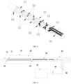
- the shock wave electrode device in this embodiment When the shock wave electrode device in this embodiment is applied to a shock wave catheter system, it needs to be wrapped around a cylindrical catheter 31, as shown in FIG. 8 .
- the shock wave electrode device 11 can be in a wrapping state along the length direction such that A-A to E-E are connected end-to-end, thereby completely covering the surface of the cylindrical catheter 31, with the four electrode gaps 15 at each location evenly distributed in the circumferential direction of the catheter 31.
- the two electrode gaps 15 are distributed and spaced at 180° interval in the circumferential direction of the catheter 31; when there are three electrode gaps 15 in the same cross-section, the electrode gaps 15 are distributed and spaced at 120° interval in the circumferential direction of the catheter 31, and so forth.
- the above interval setting method can maintain force balance of the catheter 31 during electrode discharge.
- this embodiment has a reinforcement device with an independent structure, and the reinforcement device is a metal circular ring 51.
- the inner diameter of the circular ring 51 is slightly greater than the diameter of the shock wave electrode device in the wrapping state of the shock wave electrode device 11, so that the circular ring 51 can be sleeved and fixed on the surface of the shock wave electrode device.
- the circular ring 51 is evenly distributed with four openings 52 in the circumferential direction, such that the electrode gaps 15 of the shock wave electrode device are aligned with the openings 52 of the circular ring 51 in the sleeving state to effectively expose the electrode gaps 15.
- FIG. 8 shows the situation where part of the electrode assembly 13 and electrode gaps 15 are sleeved by the circular rings 51, wherein the circular ring 53 is a circular ring 51 in the quarter section for better illustrating the positional relationship between the electrode assembly 13, the electrode gaps 15, and the circular ring 51.
- the distal end of the flexible printed circuit 12 is fixed using a developing ring 54.
- the size of the diameter of the catheter 31 and the composition of the electrode assembly 13, as well as the number and arrangement of the electrode gaps 15, can be determined according to the actual situations, wherein the electrode gap 15 can be one or a combination of polygonal, circular, arc-shaped, and annular shape, and will not be further described in this embodiment.
- this embodiment provides an implementation of a shock wave catheter system with the shock wave electrode device 11 described above, and a detailed explanation of this implementation is as follows.
- the shock wave catheter system in this embodiment is shown in FIG. 9 .
- the main components of the system include a shock wave electrode device 11 described above, a catheter 31, a developing ring 54, a balloon 61 and its independent channel 62, an independent chamber 63, a catheter joint 64, an extension wire 65, and a high-voltage electrical plug 66.
- the catheter 31 includes a proximal catheter portion located at the proximal end of the catheter 31 and a distal catheter portion extending axially to the distal end of the catheter 31.
- the balloon 61 in the form of an expandable balloon structure is arranged on the outer layer of the distal catheter portion of the catheter 31.
- a hollow portion of the balloon 61 and the independent channel 62 cooperate to form an expandable independent chamber 63.
- the flexible printed circuit 11 is disposed inside the independent chamber 63.
- the balloon 61 can withstand a relative pressure of at least one standard atmospheric pressure of the liquid medium without causing leakage of the liquid medium or rupture of the balloon 61.
- the shock wave electrode device 11 is provided with four electrode gaps 15 evenly distributed in the circumferential direction at the same cross-section of the catheter 31.
- multiple electrode gaps 15 on the same cross-section of the catheter 31 should be arranged at equal angular intervals from each other in the circumferential direction of the catheter 31.
- the two electrode gaps 15 are distributed and spaced at 180° interval in the circumferential direction of the catheter 31; when there are three electrode gaps 15 in the same cross-section, the electrode gaps 15 are distributed and spaced at 120° interval in the circumferential direction of the catheter 31, and so forth.
- the above interval setting method can maintain force balance of the catheter 31 during electrode discharge.
- the hollow portion inside the balloon 61 extends axially from the distal end of the catheter 31 to the proximal end of the catheter 31 through the independent channel 62, and is connected to the catheter joint 64.
- the liquid medium can be injected into the independent chamber 63 formed between the balloon 61 and the catheter 31 through an injection chamber in the catheter joint 64.
- the liquid medium includes water, physiological saline, contrast agent, or a mixed solution of the above liquids.
- the extension wire 65 passes through the catheter joint 64 to connect the shock wave electrode device 11 with an external energy generator 67.
- the developing ring 54 is installed on the catheter 31, and the developing ring 54 is sleeved on the catheter 31 and located inside the balloon 61.
- the sleeved developing ring 54 is located on both ends of the flexible printed circuit 12 to reinforce and protect the flexible printed circuit 12.
- the shock wave catheter system further comprises an auxiliary support structure for installing the shock wave electrode device 11, the auxiliary support structure is provided in the independent chamber 63, and the shock wave electrode device 11 is installed on the auxiliary support structure.
- the auxiliary support structure is usually one or a combination of a support tube, stent, balloon, and probe.
- the support structure can expand, open, or move within the balloon structure to achieve the function of adjusting the position of the electrode assembly 13.
- the shock wave electrode device further includes microdevices, which are integrated in the flexible printed circuit using printed circuits, or integrated on the surface of the flexible printed circuit using flip chip film packaging.
- the number of the microdevices can be any natural number such as 0, 1, 2, 3, etc.
- the microdevices can be sensors (such as temperature sensors, potential sensors, pressure sensors, impedance sensors, etc.), therapeutic devices (such as thermocouples, ablation devices, etc.), imaging devices (such as intravascular ultrasound imaging transducers, etc.), or a combination thereof.
- the shock wave electrode device 11 in this embodiment is the same as the shock wave electrode device in the second embodiment of the typical specifications.
- the flexible printed circuit 12 of the shock wave electrode device 11 is constituted by a single-layer flexible substrate 21 and two conductive pattern layers 22 located on the upper and lower surfaces of the flexible substrate 21.
- the electrode assembly 13 and some printed wires 14 are integrated in the conductive pattern layer 22 on the upper surface of the flexible substrate 21, and the conductive pattern layer 22 on the lower surface of the flexible substrate 21 is formed by printed wires 14 for achieving circuit conduction.
- the electrode assembly 13 and the printed wires 14 are printed on the surface of the flexible substrate 21 through processes such as etching, deposition, or lamination.
- the covering layer 16 covers the surface of the flexible substrate 21 integrated with the electrode assembly 13 and the printed wires 14, and forms an opening 17 at the electrode gap 15, to expose the electrode gap 15 and a portion of the electrode assembly 13 from the surface of the flexible printed circuit 12.
- the shock wave electrode device 11 is fixed to the catheter 31 by adhesion, and the upper surface of the flexible printed circuit 12 should be exposed to the internal space of the independent chamber 63, such that the electrode gap 15 can be in contact with the medium in the independent chamber 63.
- FIG. 10 shows a schematic cross-sectional view of the shock wave catheter system at the location of the electrode assembly 13.
- the shock wave catheter system includes an extension wire 65.
- a starting end of the extension wire 65 is connected to the distal end of the printed wire 14 of the shock wave electrode device 11 and extends to the outside of the catheter 31 via an energy transmission channel of the catheter joint 64.
- the other end of the extension wire 65 is connected to an external energy generator or control handle 67 via a high-voltage electrical plug 66.
- a longer flexible printed circuit 12 can be directly extended to the high-voltage electrical plug 66 through the catheter joint 64, and directly connected to channel pins 71 in the high-voltage electrical plug 66, for ultimately being connected to the external energy generator or control handle 67.
- the partial schematic diagram of this connection method is shown in FIG. 11 .
- the electrode gaps 15 can be separately connected to an energy generator 67 to achieve individual control of each shock wave generation point, for applying different voltages or currents according to the severity of the lesion site.
- multiple electrode gaps 15 can be connected together in series/parallel/mixed form and then connected to the energy generator 67 to jointly generate shock waves, for achieving a wider range of therapeutic effects.
- the shock wave electrode device in the present invention replaces the complex wires, electrodes, and other components and the arrangements of traditional intravascular shock wave generation devices through a flexible printed circuit, achieving the miniaturization and integration of liquid electric generation electrodes, reducing the manufacturing difficulty of liquid electric electrodes, increasing the density of liquid electric electrodes, and improving the uniformity of discharge energy release.
- the shock wave electrode device using this type of liquid electric electrodes can accurately control the electrode gaps, accurately locate the position of the electrodes, and has the advantages of high discharge stability, balanced and controllable shock wave energy, etc.
- the shock wave catheter system made using the shock wave electrode device provided in the present invention has the advantages of miniaturization and integration, while improving the shock wave performance and stability of the catheter, simplifying the production process of the catheter, increasing the productivity, and reducing the production cost.
Landscapes
- Health & Medical Sciences (AREA)
- Surgery (AREA)
- Life Sciences & Earth Sciences (AREA)
- Engineering & Computer Science (AREA)
- Biomedical Technology (AREA)
- Public Health (AREA)
- Vascular Medicine (AREA)
- Orthopedic Medicine & Surgery (AREA)
- Veterinary Medicine (AREA)
- Heart & Thoracic Surgery (AREA)
- Medical Informatics (AREA)
- Molecular Biology (AREA)
- Animal Behavior & Ethology (AREA)
- General Health & Medical Sciences (AREA)
- Nuclear Medicine, Radiotherapy & Molecular Imaging (AREA)
- Mechanical Engineering (AREA)
- Surgical Instruments (AREA)
- Electrotherapy Devices (AREA)
- Measurement And Recording Of Electrical Phenomena And Electrical Characteristics Of The Living Body (AREA)
Applications Claiming Priority (2)
| Application Number | Priority Date | Filing Date | Title |
|---|---|---|---|
| CN202210234318.0A CN114569194B (zh) | 2022-03-09 | 2022-03-09 | 一种冲击波电极装置及冲击波导管系统 |
| PCT/CN2023/080629 WO2023169537A1 (fr) | 2022-03-09 | 2023-03-09 | Dispositif d'électrodes à ondes de choc et système de cathéter à ondes de choc |
Publications (2)
| Publication Number | Publication Date |
|---|---|
| EP4491136A1 true EP4491136A1 (fr) | 2025-01-15 |
| EP4491136A4 EP4491136A4 (fr) | 2026-03-04 |
Family
ID=81775847
Family Applications (1)
| Application Number | Title | Priority Date | Filing Date |
|---|---|---|---|
| EP23766114.5A Pending EP4491136A4 (fr) | 2022-03-09 | 2023-03-09 | Dispositif d'électrodes à ondes de choc et système de cathéter à ondes de choc |
Country Status (4)
| Country | Link |
|---|---|
| EP (1) | EP4491136A4 (fr) |
| JP (1) | JP7645597B1 (fr) |
| CN (1) | CN114569194B (fr) |
| WO (1) | WO2023169537A1 (fr) |
Families Citing this family (12)
| Publication number | Priority date | Publication date | Assignee | Title |
|---|---|---|---|---|
| CN114569194B (zh) * | 2022-03-09 | 2024-09-03 | 江苏朴芃医疗科技有限公司 | 一种冲击波电极装置及冲击波导管系统 |
| CN115105158B (zh) * | 2022-06-15 | 2024-05-03 | 上海百心安生物技术股份有限公司 | 一种封闭电极脉冲球囊扩张导管 |
| CN117481743A (zh) * | 2022-07-26 | 2024-02-02 | 苏州生科智能科技有限公司 | 一种冲击波球囊导管装置 |
| CN117503265B (zh) * | 2022-07-26 | 2025-08-22 | 苏州生科智能科技有限公司 | 一种冲击波球囊导管装置 |
| CN116999118A (zh) * | 2022-09-20 | 2023-11-07 | 苏州润迈德智能科技发展有限公司 | 一种冲击波球囊导管装置 |
| CN115414089B (zh) * | 2022-10-10 | 2025-04-08 | 江苏朴芃医疗科技有限公司 | 冲击波治疗导管系统 |
| CN118252573A (zh) * | 2022-12-20 | 2024-06-28 | 苏州生科智能科技有限公司 | 一种冲击波球囊导管装置 |
| CN119454211A (zh) * | 2023-07-31 | 2025-02-18 | 苏州生科智能科技有限公司 | 一种冲击波球囊导管装置 |
| US12496078B2 (en) | 2023-08-24 | 2025-12-16 | Shockwave Medical, Inc. | Lithotripsy catheters having electrodes formed in metallization layers |
| WO2025117776A1 (fr) * | 2023-11-30 | 2025-06-05 | Shockwave Medical, Inc. | Systèmes, dispositifs et procédés de traitement de matériau cible dans une lumière corporelle avec des ondes de choc |
| CN119235410B (zh) * | 2024-03-22 | 2025-09-02 | 睿伏医疗科技(北京)有限公司 | 冲击波电极及冲击波盲端球囊导管 |
| CN119770124B (zh) * | 2025-01-23 | 2025-11-04 | 深圳纯和医药有限公司 | 一种电极可移动的冲击波球囊导管及医疗设备 |
Family Cites Families (12)
| Publication number | Priority date | Publication date | Assignee | Title |
|---|---|---|---|---|
| EP2076194B1 (fr) * | 2006-10-18 | 2013-04-24 | Vessix Vascular, Inc. | Système pour induire des effets thermiques désirables sur un tissu anatomique |
| WO2010056771A1 (fr) * | 2008-11-11 | 2010-05-20 | Shifamed Llc | Ensemble d’électrodes à faible profil |
| US9642673B2 (en) | 2012-06-27 | 2017-05-09 | Shockwave Medical, Inc. | Shock wave balloon catheter with multiple shock wave sources |
| EP3777703B1 (fr) * | 2013-02-08 | 2023-04-05 | Acutus Medical Inc. | Ensemble cathéter extensible doté d'une carte de circuit imprimé souple |
| US9485873B2 (en) * | 2013-03-15 | 2016-11-01 | Lawrence Livermore National Security, Llc | Depositing bulk or micro-scale electrodes |
| US10070880B2 (en) * | 2013-04-15 | 2018-09-11 | Actuated Medical, Inc. | Miniature device platform for navigation on moving organs |
| CN203386506U (zh) * | 2013-07-30 | 2014-01-08 | 中国科学院上海技术物理研究所 | 低漏热柔性电缆 |
| CN113951973A (zh) * | 2020-12-16 | 2022-01-21 | 深圳市赛禾医疗技术有限公司 | 一种压力波球囊导管 |
| CN112932651B (zh) * | 2021-03-24 | 2025-02-21 | 上海微创旋律医疗科技有限公司 | 电极部件及电极球囊导管 |
| CN113440215A (zh) * | 2021-07-23 | 2021-09-28 | 上海佳沐垚医疗科技有限公司 | 一种冲击波发生装置及导管系统 |
| CN113633346B (zh) * | 2021-08-31 | 2024-05-03 | 苏州中荟医疗科技有限公司 | 一种电极装置及冲击波发生系统 |
| CN114569194B (zh) * | 2022-03-09 | 2024-09-03 | 江苏朴芃医疗科技有限公司 | 一种冲击波电极装置及冲击波导管系统 |
-
2022
- 2022-03-09 CN CN202210234318.0A patent/CN114569194B/zh active Active
-
2023
- 2023-03-09 EP EP23766114.5A patent/EP4491136A4/fr active Pending
- 2023-03-09 JP JP2024553716A patent/JP7645597B1/ja active Active
- 2023-03-09 WO PCT/CN2023/080629 patent/WO2023169537A1/fr not_active Ceased
Also Published As
| Publication number | Publication date |
|---|---|
| CN114569194B (zh) | 2024-09-03 |
| JP2025508284A (ja) | 2025-03-25 |
| CN114569194A (zh) | 2022-06-03 |
| EP4491136A4 (fr) | 2026-03-04 |
| JP7645597B1 (ja) | 2025-03-14 |
| WO2023169537A1 (fr) | 2023-09-14 |
Similar Documents
| Publication | Publication Date | Title |
|---|---|---|
| EP4491136A1 (fr) | Dispositif d'électrodes à ondes de choc et système de cathéter à ondes de choc | |
| US12303190B2 (en) | Catheter distal end made of plastic tube and flexible printed circuit boards | |
| EP4134022A1 (fr) | Systèmes de ballonnet de lithoplastie, dispositifs et procédés avec des paires d'électrode dotées de plusieurs espaces d'allumage | |
| US20260114887A1 (en) | Systems, devices and methods for generating patterns of voltage pulses and electrical arcs between spaced-apart electrode pairs in intravascular lithotripsy | |
| CN115463317B (zh) | 一种冲击波球囊导管 | |
| US11801066B2 (en) | Systems, devices and methods for selection of arc location within a lithoplasty balloon spark gap | |
| US20230038388A1 (en) | Lithoplasty balloon systems, devices and methods with electrode pairs having multiple spark gaps | |
| EP3949884A1 (fr) | Dispositif médical | |
| WO2024060518A1 (fr) | Dispositif de cathéter à ballonnet à ondes de choc | |
| WO2024021604A1 (fr) | Dispositif cathéter a ballonnet à ondes de choc | |
| CN117503265B (zh) | 一种冲击波球囊导管装置 | |
| CN114795386B (zh) | 冲击波发生组件、电极球囊导管及制作方法 | |
| CN218832829U (zh) | 一种冲击波球囊导管装置 | |
| CN118252573A (zh) | 一种冲击波球囊导管装置 | |
| WO2023137079A1 (fr) | Adaptateur pour système de cathéter modulaire électrique | |
| CN119970156A (zh) | 冲击波发生装置及冲击波治疗导管系统 | |
| WO2025043092A1 (fr) | Cathéters de lithotripsie avec des électrodes formées dans des couches de métallisation | |
| CN120241179A (zh) | 冲击波球囊导管和冲击波系统 | |
| HK40011281A (en) | Steerable medical device and the preparing method thereof | |
| HK40011281B (en) | Steerable medical device and the preparing method thereof |
Legal Events
| Date | Code | Title | Description |
|---|---|---|---|
| STAA | Information on the status of an ep patent application or granted ep patent |
Free format text: STATUS: THE INTERNATIONAL PUBLICATION HAS BEEN MADE |
|
| PUAI | Public reference made under article 153(3) epc to a published international application that has entered the european phase |
Free format text: ORIGINAL CODE: 0009012 |
|
| STAA | Information on the status of an ep patent application or granted ep patent |
Free format text: STATUS: REQUEST FOR EXAMINATION WAS MADE |
|
| 17P | Request for examination filed |
Effective date: 20240904 |
|
| AK | Designated contracting states |
Kind code of ref document: A1 Designated state(s): AL AT BE BG CH CY CZ DE DK EE ES FI FR GB GR HR HU IE IS IT LI LT LU LV MC ME MK MT NL NO PL PT RO RS SE SI SK SM TR |
|
| DAV | Request for validation of the european patent (deleted) | ||
| DAX | Request for extension of the european patent (deleted) | ||
| A4 | Supplementary search report drawn up and despatched |
Effective date: 20260202 |
|
| RIC1 | Information provided on ipc code assigned before grant |
Ipc: A61B 17/22 20060101AFI20260127BHEP |