EP4491162A1 - Un dispositiv portable de froid et de chaud - Google Patents
Un dispositiv portable de froid et de chaud Download PDFInfo
- Publication number
- EP4491162A1 EP4491162A1 EP23184565.2A EP23184565A EP4491162A1 EP 4491162 A1 EP4491162 A1 EP 4491162A1 EP 23184565 A EP23184565 A EP 23184565A EP 4491162 A1 EP4491162 A1 EP 4491162A1
- Authority
- EP
- European Patent Office
- Prior art keywords
- layer
- fan
- belt
- cold
- thermoelectric module
- Prior art date
- Legal status (The legal status is an assumption and is not a legal conclusion. Google has not performed a legal analysis and makes no representation as to the accuracy of the status listed.)
- Pending
Links
Images





Classifications
-
- A—HUMAN NECESSITIES
- A61—MEDICAL OR VETERINARY SCIENCE; HYGIENE
- A61F—FILTERS IMPLANTABLE INTO BLOOD VESSELS; PROSTHESES; DEVICES PROVIDING PATENCY TO, OR PREVENTING COLLAPSING OF, TUBULAR STRUCTURES OF THE BODY, e.g. STENTS; ORTHOPAEDIC, NURSING OR CONTRACEPTIVE DEVICES; FOMENTATION; TREATMENT OR PROTECTION OF EYES OR EARS; BANDAGES, DRESSINGS OR ABSORBENT PADS; FIRST-AID KITS
- A61F7/00—Heating or cooling appliances for medical or therapeutic treatment of the human body
- A61F7/007—Heating or cooling appliances for medical or therapeutic treatment of the human body characterised by electric heating
-
- A—HUMAN NECESSITIES
- A61—MEDICAL OR VETERINARY SCIENCE; HYGIENE
- A61F—FILTERS IMPLANTABLE INTO BLOOD VESSELS; PROSTHESES; DEVICES PROVIDING PATENCY TO, OR PREVENTING COLLAPSING OF, TUBULAR STRUCTURES OF THE BODY, e.g. STENTS; ORTHOPAEDIC, NURSING OR CONTRACEPTIVE DEVICES; FOMENTATION; TREATMENT OR PROTECTION OF EYES OR EARS; BANDAGES, DRESSINGS OR ABSORBENT PADS; FIRST-AID KITS
- A61F7/00—Heating or cooling appliances for medical or therapeutic treatment of the human body
- A61F2007/0001—Body part
- A61F2007/0018—Trunk or parts thereof
- A61F2007/0023—Waist
-
- A—HUMAN NECESSITIES
- A61—MEDICAL OR VETERINARY SCIENCE; HYGIENE
- A61F—FILTERS IMPLANTABLE INTO BLOOD VESSELS; PROSTHESES; DEVICES PROVIDING PATENCY TO, OR PREVENTING COLLAPSING OF, TUBULAR STRUCTURES OF THE BODY, e.g. STENTS; ORTHOPAEDIC, NURSING OR CONTRACEPTIVE DEVICES; FOMENTATION; TREATMENT OR PROTECTION OF EYES OR EARS; BANDAGES, DRESSINGS OR ABSORBENT PADS; FIRST-AID KITS
- A61F7/00—Heating or cooling appliances for medical or therapeutic treatment of the human body
- A61F7/007—Heating or cooling appliances for medical or therapeutic treatment of the human body characterised by electric heating
- A61F2007/0075—Heating or cooling appliances for medical or therapeutic treatment of the human body characterised by electric heating using a Peltier element, e.g. near the spot to be heated or cooled
-
- A—HUMAN NECESSITIES
- A61—MEDICAL OR VETERINARY SCIENCE; HYGIENE
- A61F—FILTERS IMPLANTABLE INTO BLOOD VESSELS; PROSTHESES; DEVICES PROVIDING PATENCY TO, OR PREVENTING COLLAPSING OF, TUBULAR STRUCTURES OF THE BODY, e.g. STENTS; ORTHOPAEDIC, NURSING OR CONTRACEPTIVE DEVICES; FOMENTATION; TREATMENT OR PROTECTION OF EYES OR EARS; BANDAGES, DRESSINGS OR ABSORBENT PADS; FIRST-AID KITS
- A61F7/00—Heating or cooling appliances for medical or therapeutic treatment of the human body
- A61F2007/0093—Heating or cooling appliances for medical or therapeutic treatment of the human body programmed
-
- A—HUMAN NECESSITIES
- A61—MEDICAL OR VETERINARY SCIENCE; HYGIENE
- A61F—FILTERS IMPLANTABLE INTO BLOOD VESSELS; PROSTHESES; DEVICES PROVIDING PATENCY TO, OR PREVENTING COLLAPSING OF, TUBULAR STRUCTURES OF THE BODY, e.g. STENTS; ORTHOPAEDIC, NURSING OR CONTRACEPTIVE DEVICES; FOMENTATION; TREATMENT OR PROTECTION OF EYES OR EARS; BANDAGES, DRESSINGS OR ABSORBENT PADS; FIRST-AID KITS
- A61F7/00—Heating or cooling appliances for medical or therapeutic treatment of the human body
- A61F7/02—Compresses or poultices for effecting heating or cooling
- A61F2007/0225—Compresses or poultices for effecting heating or cooling connected to the body or a part thereof
- A61F2007/0228—Compresses or poultices for effecting heating or cooling connected to the body or a part thereof with belt or strap, e.g. with buckle
-
- A—HUMAN NECESSITIES
- A61—MEDICAL OR VETERINARY SCIENCE; HYGIENE
- A61F—FILTERS IMPLANTABLE INTO BLOOD VESSELS; PROSTHESES; DEVICES PROVIDING PATENCY TO, OR PREVENTING COLLAPSING OF, TUBULAR STRUCTURES OF THE BODY, e.g. STENTS; ORTHOPAEDIC, NURSING OR CONTRACEPTIVE DEVICES; FOMENTATION; TREATMENT OR PROTECTION OF EYES OR EARS; BANDAGES, DRESSINGS OR ABSORBENT PADS; FIRST-AID KITS
- A61F7/00—Heating or cooling appliances for medical or therapeutic treatment of the human body
- A61F7/02—Compresses or poultices for effecting heating or cooling
- A61F2007/0295—Compresses or poultices for effecting heating or cooling for heating or cooling or use at more than one temperature
Definitions
- the challenge is to develop a device that allows the benefits of cold and heat therapy to be combined in a comfortable and flexible way. This requires that the heat energy is transferred directly to the body part without disturbing the contact with additional elements such as splayed fingers.
- thermoelectric element a material layer is applied to the top of the thermoelectric element.
- the material layer can consist of an aluminum plate, for example.
- the fan is used to increase airflow over a heat sink and improve cooling performance.
- the fan dissipates heat by blowing the surrounding air over the heat sink, thus assisting in cooling the thermoelectric element.
- caloric materials such as magnetocaloric and electrocaloric materials can also be used. These materials use the caloric effects to generate or dissipate heat energy.
- the electrocaloric principle uses the change in the electric field strength to generate temperature changes in a material. By applying or removing an electrical voltage, heat energy is generated or dissipated.
- the cold and heat device comprises a control device and a battery device to operate the thermoelectric module and the fan.
- the control device can, for example, be configured to control the treatment in terms of duration, temperature ranges and cycles.
- thermoelectric module and/or the fan can be attached only to the first layer. This structure ensures maximum flexibility.
- thermoelectric module and/or the fan can be attached to the first layer and to the second layer. This ensures good alignment of the thermoelectric module and the fan to each other. This can optimize the cooling of the thermoelectric module.
- centrifugal fan is a type of fan that moves air or gas radially from the center of the fan outward. Unlike axial fans, where the air flows parallel to the axis of rotation of the fan, radial fans move the air perpendicular to the axis of rotation. Radial fans are also known by the term “centrifugal fan” or “centrifugal fan.”
- a radial fan typically consists of a housing in which an impeller or rotor is located.
- the impeller in one example, consists of curved blades arranged radially. When the impeller rotates, it creates a centrifugal force that pushes the air outward from the center of the fan. The air then flows through the housing and is expelled sideways or forwards.
- the use of radial fans enables a particularly flat design of the device in contrast to axial fans.
- the fan is oriented to generate an air flow between the first and second layers.
- the fan can be designed as a radial fan and the inlet opening of the radial fan can be arranged at the first and/or second layer.
- the fan can be designed as an axial fan and the inlet opening of the axial fan can be arranged between the first and second length. This allows a direct cooling air flow to the thermoelectric module, in particular to the heat-dissipating elements such as heat sinks.
- the space between the first and second layers is essentially defined by the height of the thermoelectric module and the fan.
- an outlet opening is arranged downstream of the air, wherein the outlet opening is arranged in the second layer or between the first and second layers.
- the outlet opening is arranged downstream of the thermoelectric module.
- Downstream airflow refers to the airflow direction from the fan to the outlet, with the thermoelectric module essentially being arranged between the fan and the outlet opening.
- Arranging the outlet opening between the first and second layers has the advantage that the heat of the thermoelectric module can be better dissipated when the user wears the device under clothing.
- the width of the fan is approximately the same size, so that the flexibility of the belt when attached or wrapped to a part of the body is determined by the width of the thermoelectric module and the flexibility.
- the width of the fan and the thermoelectric module is the length that runs along the longitudinal or circumferential direction of the belt.
- the first layer and/or the second layer of the belt have recesses in order to arrange the thermoelectric module and/or the fan on the belt.
- thermoelectric module is attached to the first layer and/or second layer of the belt in a material-locking manner, preferably glued, and/or form-fitting manner, preferably by a snap fastener, and/or the fan is glued to the first layer and/or second layer of the belt and/or attached by a snap fastener.
- the first layer has a lower buckling stiffness than the second layer.
- thermoelectric elements preferably Peltier elements
- Flexibility can also be understood as low buckling stiffness.
- thermoelectric modules and fans with respective outlet openings are arranged along the circumferential direction of the belt in a temperature transfer region at a distance of at least 0.1 cm to at most 10 cm, preferably 1 cm - 3 cm.
- thermoelectric element especially a Peltier element
- thermoelectric element preferably the Peltier element
- the tensioning device has spacer elements to adjust the contact pressure along the belt.
- the cold and heat device has a temperature distribution layer which can be attached to a side of the first layer of the belt facing the body part. This enables a broad and even distribution of the thermal energy of the thermoelectric module to the temperature distribution layer and thus to the body part to be treated.
- the temperature distribution layer can also be referred to as a flexible heat transfer layer and can consist of a heat-conducting polymer, e.g. heat-conducting silicone, or heat-conducting TPU.
- thermoelectric element has at least two Peltier elements. This allows the heat energy that can be generated by the thermoelectric module to be increased and greater temperature differences between the cold and heat cycles and thus greater efficiency to be achieved.
- thermoelectric module further comprises a heat sink which is fixed to the thermoelectric element by a frame.
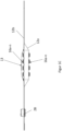
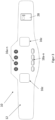
- Figure 1A shows a front side and Figure 1B a rear side of a portable cold and heat device 10 for tempering a body part, comprising a belt 12 consisting of at least two essentially at least partially superimposed layers 12a, 12b (see Figure 1C ) and at least one thermoelectric module 14a-n having at least one thermoelectric element 141, preferably a Peltier element.
- the device also has at least one fan 16a-n, preferably a radial fan.
- the belt 12 has a first layer 12a, which faces the body part, and a second layer 12b, which faces away from the body part.
- thermoelectric module 14a-n and/or the fan 16a-n are attached at least to the first layer 12a and/or second layer 12b, wherein the thermoelectric module 14a-n and the fan 16a-n are arranged separately from one another on the belt 12.
- the belt 12 has a fastening area 26 (eg Velcro fastener) to fix it after it has been tied or wrapped around a body part (not shown).
- a fastening area 26 eg Velcro fastener
- thermoelectric modules 14a-n are arranged in two rows each running parallel in the circumferential direction UR, each with four thermoelectric modules 14a-n.
- the temperature transfer area A is defined by the arrangement of the thermoelectric modules 14a-n.
- thermoelectric module 14a-n and the at least one fan 16a-n are located on a straight line G transverse to the circumferential direction UR.
- thermoelectric module 14a-n This arrangement allows maximum flexibility of the belt 12 to be achieved, since this is determined by the width B of the thermoelectric module 14a-n.
- the width B of the radial fan shown here as an example is smaller than or equal to the width of the thermoelectric module in order to ensure the flexibility of the belt 12 in the region of the temperature transfer area A.
- several small thermoelectric modules 14a-n distributed across the temperature transfer area A in terms of width increase the flexibility of the belt without reducing the transfer of heat energy to the body part.
- the width B of the fan 16a-n with respect to the circumferential direction UR of the belt 12 is dimensioned by -5% to 50%, preferably -5% to 25%, particularly preferably -5% to 5% compared to the width B of the thermoelectric module 14a-n.
- the air flow guide rails 24 are attached to the first layer 12a and the second layer 12b such that they form an air flow channel transverse to the circumferential direction in the direction of the respective fan 16a-n and the respective outlet opening 18a-n between the first layer 12a and the second layer 12b.
- Figure 1B shows the device from the back or from the side that does not face the body part or is facing away from the body part.
- outlet openings 18a-n are provided which direct the air flow that cools the thermoelectric module to the outside.
- These outlet openings 18a-n are preferably also arranged on the same straight line G as the thermoelectric module 14a-n and the fan 16a-n.
- the respective outlet opening 18a-n can be arranged in the second layer 12b so that the exhaust air is guided to the outside via the side facing away from the body part.
- the outlet openings 18a-n can be arranged between the first layer 12a and the second layer 12b (not shown). This has the advantage that the exhaust air is not partially blocked by external means, such as clothing. This ensures that the device 10 can also be worn under clothing in everyday life.
- Figure 1C shows the device in a side view.
- the first layer 12a is arranged partially over the second layer 12b.
- the first layer 12a and/or the second layer 12b are connected, for example sewn together, in such a way that they form a front side.
- the inlet openings and the outlet openings can be arranged on the front side (not shown).
- the inlet openings of the fan 16a-n can be arranged on the first and second layers. This ensures maximum air flow generation of the fan 16a-n.
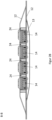
- FIG 2A shows a sectional view AA transverse to the circumferential direction UR.
- the thermoelectric module 14 has two Peltier elements 141a, 141b.
- the thermoelectric modules are connected to the control device 28 (not shown) via cables.
- the thermoelectric modules 14a-n are connected to the second layer 12b via the rear side.
- the thermoelectric modules 14a-n are connected to the second layer 12b via a plate 30 (see also Figure 7 ).
- the screws can, for example, be screwed directly into the heat sink 142 using self-tapping screws.
- the top of the thermoelectric element is in direct contact with the body part and is designed to be slightly offset or flush with the first layer 12a.
- an outlet opening 18 is provided on the second layer 12b.
- the back of the device 10 may have a cover layer 13, wherein an opening is provided with the outlet opening 18 of the second layer 12b.
- fan 16a-n preferably a radial fan, is oriented to generate an air flow between the first 12a and second layer 12b.
- the first layer 12a and/or the second layer 12b of the belt 12 have recesses in order to arrange the thermoelectric module 14a-n and/or the fan 16a-n on the belt (12).
- This allows the top side of the thermoelectric element 141 in particular to come into direct contact with the body part to be treated, so that the thermal energy of the thermoelectric element 141, preferably Peltier element, can be transferred directly to the body part and does not have to first diffuse through the fabric layer of the first layer 12a.
- thermoelectric element 141 can be further increased by arranging at least one further fan 16z at each end of the temperature transfer region A along the circumferential direction UR.
- Figure 4 also shows, by way of example, a tensioning device 20 so that the belt 12 can be pressed against the body part at least in the temperature transfer area A.
- the tensioning device 20 has spacer elements 21 in order to adjust the contact pressure along the temperature transfer area A at a body part K.
- the flexible air flow guide rails 24 are designed to be so flexible that they adapt to the contour of the body part to be treated. This can improve the cooling of the device without sacrificing flexibility for the belt.
- the device 10 can have a temperature distribution layer 22, which can be attached to a side of the first layer 12a of the belt 12 facing the body part. This enables a broad and even distribution of the thermal energy of the thermoelectric module to the temperature distribution layer and thus to the body part to be treated.
- the temperature distribution layer 22 can also be referred to as a flexible heat transfer layer and can consist of a thermally conductive polymer, eg thermally conductive silicone, or thermally conductive TPU.
- thermoelectric module 14 comprising a thermoelectric element 141, a heat sink 142 and a frame 143.
- the thermoelectric element 141 can comprise at least two Peltier elements 141a, 141b as shown here by way of example.
- the thermoelectric module 14 can further comprise a heat sink 142 which is fixed to the thermoelectric element 141 by a frame 143.
- the device has a plate 30 which is applied to the second layer 12b from the outside and is connected to the heat sink 142 of the thermoelectric module via a screw connection, preferably self-tapping screws.
- thermoelectric module 14a-n and an axial fan are connected to each other and attached to the belt 12 via the back of the axial fan.
- the axial fan and the thermoelectric module are designed as a unit and attached to the belt 12 like a bell.
- the thermoelectric modules hang down freely and are flexibly attached via a fastening can be swiveled on the belt.
- the belt is arranged on the back of the axial fan and thus presses the thermoelectric modules in the wound state efficiently to the part of the body.
Landscapes
- Health & Medical Sciences (AREA)
- Engineering & Computer Science (AREA)
- Biomedical Technology (AREA)
- Heart & Thoracic Surgery (AREA)
- Vascular Medicine (AREA)
- Life Sciences & Earth Sciences (AREA)
- Animal Behavior & Ethology (AREA)
- General Health & Medical Sciences (AREA)
- Public Health (AREA)
- Veterinary Medicine (AREA)
- Thermotherapy And Cooling Therapy Devices (AREA)
Priority Applications (2)
| Application Number | Priority Date | Filing Date | Title |
|---|---|---|---|
| EP23184565.2A EP4491162A1 (fr) | 2023-07-10 | 2023-07-10 | Un dispositiv portable de froid et de chaud |
| PCT/EP2024/054228 WO2025011783A1 (fr) | 2023-07-10 | 2024-02-20 | Dispositif portable de refroidissement et de chauffage |
Applications Claiming Priority (1)
| Application Number | Priority Date | Filing Date | Title |
|---|---|---|---|
| EP23184565.2A EP4491162A1 (fr) | 2023-07-10 | 2023-07-10 | Un dispositiv portable de froid et de chaud |
Publications (1)
| Publication Number | Publication Date |
|---|---|
| EP4491162A1 true EP4491162A1 (fr) | 2025-01-15 |
Family
ID=87245749
Family Applications (1)
| Application Number | Title | Priority Date | Filing Date |
|---|---|---|---|
| EP23184565.2A Pending EP4491162A1 (fr) | 2023-07-10 | 2023-07-10 | Un dispositiv portable de froid et de chaud |
Country Status (2)
| Country | Link |
|---|---|
| EP (1) | EP4491162A1 (fr) |
| WO (1) | WO2025011783A1 (fr) |
Citations (5)
| Publication number | Priority date | Publication date | Assignee | Title |
|---|---|---|---|---|
| US4741338A (en) * | 1986-10-06 | 1988-05-03 | Toshiaki Miyamae | Thermoelectric physical remedy apparatus |
| EP3975948A1 (fr) * | 2019-06-03 | 2022-04-06 | Cooler Heads Care, Inc. | Ensemble bonnet de refroidissement et unité de refroidissement |
| WO2022133209A1 (fr) | 2020-12-17 | 2022-06-23 | Therabody, Inc. | Vêtement thérapeutique vibrant à température commandée |
| DE102021125746A1 (de) * | 2021-02-08 | 2022-08-11 | Chin-Hwa Hwang | Flexible Kalt- und Warmkompresse |
| WO2023031245A1 (fr) * | 2021-09-01 | 2023-03-09 | Markus Hintennach | Dispositif de refroidissement |
Family Cites Families (4)
| Publication number | Priority date | Publication date | Assignee | Title |
|---|---|---|---|---|
| GB201510279D0 (en) * | 2015-06-12 | 2015-07-29 | Swellaway Ltd | Therapeutic apparatus |
| CN116648223A (zh) * | 2020-12-17 | 2023-08-25 | 泰乐博迪股份有限公司 | 具有振动和温度控制的气动压缩装置 |
| US20220287873A1 (en) * | 2021-03-14 | 2022-09-15 | Aleksandr Taslagyan | Body temperature regulation |
| CN217908142U (zh) * | 2022-05-18 | 2022-11-29 | 吴金轩 | 一种输液固定板 |
-
2023
- 2023-07-10 EP EP23184565.2A patent/EP4491162A1/fr active Pending
-
2024
- 2024-02-20 WO PCT/EP2024/054228 patent/WO2025011783A1/fr not_active Ceased
Patent Citations (5)
| Publication number | Priority date | Publication date | Assignee | Title |
|---|---|---|---|---|
| US4741338A (en) * | 1986-10-06 | 1988-05-03 | Toshiaki Miyamae | Thermoelectric physical remedy apparatus |
| EP3975948A1 (fr) * | 2019-06-03 | 2022-04-06 | Cooler Heads Care, Inc. | Ensemble bonnet de refroidissement et unité de refroidissement |
| WO2022133209A1 (fr) | 2020-12-17 | 2022-06-23 | Therabody, Inc. | Vêtement thérapeutique vibrant à température commandée |
| DE102021125746A1 (de) * | 2021-02-08 | 2022-08-11 | Chin-Hwa Hwang | Flexible Kalt- und Warmkompresse |
| WO2023031245A1 (fr) * | 2021-09-01 | 2023-03-09 | Markus Hintennach | Dispositif de refroidissement |
Also Published As
| Publication number | Publication date |
|---|---|
| WO2025011783A1 (fr) | 2025-01-16 |
Similar Documents
| Publication | Publication Date | Title |
|---|---|---|
| DE19715461B4 (de) | Vorrichtung zur Behandlung des menschlichen Körpers | |
| AT407480B (de) | Heizeinrichtung zum erwärmen einer hautoberfläche bzw. teilbereiche eines menschlichen körpers | |
| DE102012210275B4 (de) | Haartrockner | |
| EP1462073B1 (fr) | Dispositif de chauffage et de refroidissement | |
| AT516054B1 (de) | Tragbare Vorrichtung zur Kühlung | |
| DE29914199U1 (de) | Multifunktionale Augenmaske | |
| WO2012156052A2 (fr) | Dispositif de stimulation | |
| EP4000567A1 (fr) | Dispositif de traitement thérapeutique par la chaleur d'une zone corporelle sélectionnée d'un humain ou d'un animal et procédé de fonctionnement dudit appareil | |
| EP4491162A1 (fr) | Un dispositiv portable de froid et de chaud | |
| WO1984002071A1 (fr) | Dispositif de compresses froides ou chaudes | |
| DE2613776A1 (de) | Schutzdecke fuer pferde oder dergleichen tiere | |
| EP3337440B1 (fr) | Appareil de therapie | |
| EP2991466A2 (fr) | Dispositif de regulation de la temperature dans une piece et armoire electrique equipee d'un tel dispositif de regulation de la temperature | |
| EP1940330A2 (fr) | Dispositif de maintien pour cage thoracique | |
| EP4395722A1 (fr) | Dispositif de refroidissement | |
| DE3410413A1 (de) | Temperiersystem | |
| DE202013102909U1 (de) | Apparat für die Wärme- und Kältebehandlung der Augen | |
| DE102017108840B4 (de) | Stützkörper mit Massagewirkung und Bandage | |
| AT526059B1 (de) | Mobile elektrische vorrichtung zur abgabe von strahlungswärme für die wärmeanwendung | |
| EP2194940B1 (fr) | Dispositif de régulation de la température servant à réguler la température de parties cutanées du corps humain | |
| DE102024124471A1 (de) | Eine tragbare Kälte- und Wärmevorrichtung mit einer Temperaturverteilereinrichtung | |
| DE102017101625B4 (de) | Blaulicht-Therapiegerät | |
| DE102016003630A1 (de) | Modulare Funktionsbandage zur Einstellung eines Wirkparameters und dazugehöriges Verfahren | |
| DE3707756C2 (fr) | ||
| DE102019102007B4 (de) | Therapeutische Kopfbedeckung |
Legal Events
| Date | Code | Title | Description |
|---|---|---|---|
| STAA | Information on the status of an ep patent application or granted ep patent |
Free format text: STATUS: UNKNOWN |
|
| PUAI | Public reference made under article 153(3) epc to a published international application that has entered the european phase |
Free format text: ORIGINAL CODE: 0009012 |
|
| STAA | Information on the status of an ep patent application or granted ep patent |
Free format text: STATUS: THE APPLICATION HAS BEEN PUBLISHED |
|
| AK | Designated contracting states |
Kind code of ref document: A1 Designated state(s): AL AT BE BG CH CY CZ DE DK EE ES FI FR GB GR HR HU IE IS IT LI LT LU LV MC ME MK MT NL NO PL PT RO RS SE SI SK SM TR |
|
| STAA | Information on the status of an ep patent application or granted ep patent |
Free format text: STATUS: REQUEST FOR EXAMINATION WAS MADE |
|
| 17P | Request for examination filed |
Effective date: 20250715 |