EP4491164A2 - Système et procédé chirurgicaux laser ophtalmique pour l'extraction de lenticule cornéen guidée par front d'onde pour la correction de la vision - Google Patents
Système et procédé chirurgicaux laser ophtalmique pour l'extraction de lenticule cornéen guidée par front d'onde pour la correction de la vision Download PDFInfo
- Publication number
- EP4491164A2 EP4491164A2 EP24207471.4A EP24207471A EP4491164A2 EP 4491164 A2 EP4491164 A2 EP 4491164A2 EP 24207471 A EP24207471 A EP 24207471A EP 4491164 A2 EP4491164 A2 EP 4491164A2
- Authority
- EP
- European Patent Office
- Prior art keywords
- cornea
- spherical
- wavefront map
- eye
- wavefront
- Prior art date
- Legal status (The legal status is an assumption and is not a legal conclusion. Google has not performed a legal analysis and makes no representation as to the accuracy of the status listed.)
- Pending
Links
- 238000000034 method Methods 0.000 title claims abstract description 46
- 238000012937 correction Methods 0.000 title claims description 58
- 238000000605 extraction Methods 0.000 title abstract description 19
- 230000004438 eyesight Effects 0.000 title description 5
- 210000004087 cornea Anatomy 0.000 claims abstract description 200
- 238000005259 measurement Methods 0.000 claims abstract description 24
- 230000003287 optical effect Effects 0.000 claims description 80
- 230000008878 coupling Effects 0.000 claims description 17
- 238000010168 coupling process Methods 0.000 claims description 17
- 238000005859 coupling reaction Methods 0.000 claims description 17
- 238000004590 computer program Methods 0.000 claims 5
- 208000001491 myopia Diseases 0.000 abstract description 5
- 230000004379 myopia Effects 0.000 abstract description 5
- 230000015572 biosynthetic process Effects 0.000 abstract 1
- 210000001519 tissue Anatomy 0.000 description 15
- 230000006870 function Effects 0.000 description 11
- 230000004075 alteration Effects 0.000 description 9
- 230000005499 meniscus Effects 0.000 description 9
- 239000000463 material Substances 0.000 description 8
- 101100129500 Caenorhabditis elegans max-2 gene Proteins 0.000 description 7
- 238000010586 diagram Methods 0.000 description 6
- 238000003860 storage Methods 0.000 description 5
- 230000007704 transition Effects 0.000 description 5
- 230000009466 transformation Effects 0.000 description 4
- 230000008901 benefit Effects 0.000 description 3
- 238000004364 calculation method Methods 0.000 description 3
- 201000006318 hyperopia Diseases 0.000 description 3
- 230000004305 hyperopia Effects 0.000 description 3
- 230000004048 modification Effects 0.000 description 3
- 238000012986 modification Methods 0.000 description 3
- 230000002093 peripheral effect Effects 0.000 description 3
- WANLLPADDCXPGO-UHFFFAOYSA-N Cyl-2 Natural products N1C(=O)C(CCCCCC(=O)C2OC2)NC(=O)C2CCCCN2C(=O)C(C(C)CC)NC(=O)C1CC1=CC=C(OC)C=C1 WANLLPADDCXPGO-UHFFFAOYSA-N 0.000 description 2
- 108010063406 Cyl-2 Proteins 0.000 description 2
- 206010020675 Hypermetropia Diseases 0.000 description 2
- 201000009310 astigmatism Diseases 0.000 description 2
- 210000003683 corneal stroma Anatomy 0.000 description 2
- 238000005516 engineering process Methods 0.000 description 2
- 210000000981 epithelium Anatomy 0.000 description 2
- 238000003384 imaging method Methods 0.000 description 2
- 230000007246 mechanism Effects 0.000 description 2
- 230000000644 propagated effect Effects 0.000 description 2
- 210000001747 pupil Anatomy 0.000 description 2
- 208000014733 refractive error Diseases 0.000 description 2
- WANLLPADDCXPGO-WMKJBNATSA-N (6r,9s,12s)-3-[(2s)-butan-2-yl]-6-[(4-methoxyphenyl)methyl]-9-[6-(oxiran-2-yl)-6-oxohexyl]-1,4,7,10-tetrazabicyclo[10.4.0]hexadecane-2,5,8,11-tetrone Chemical compound C([C@@H]1C(=O)NC(C(N2CCCC[C@H]2C(=O)N[C@@H](CCCCCC(=O)C2OC2)C(=O)N1)=O)[C@@H](C)CC)C1=CC=C(OC)C=C1 WANLLPADDCXPGO-WMKJBNATSA-N 0.000 description 1
- 208000002177 Cataract Diseases 0.000 description 1
- 241000700608 Sagitta Species 0.000 description 1
- 238000002679 ablation Methods 0.000 description 1
- 230000002411 adverse Effects 0.000 description 1
- 238000013459 approach Methods 0.000 description 1
- 230000009286 beneficial effect Effects 0.000 description 1
- 230000015556 catabolic process Effects 0.000 description 1
- 230000008859 change Effects 0.000 description 1
- 238000010226 confocal imaging Methods 0.000 description 1
- 230000006735 deficit Effects 0.000 description 1
- 238000009795 derivation Methods 0.000 description 1
- 238000013461 design Methods 0.000 description 1
- 238000011161 development Methods 0.000 description 1
- 230000018109 developmental process Effects 0.000 description 1
- 238000006073 displacement reaction Methods 0.000 description 1
- 239000000835 fiber Substances 0.000 description 1
- 239000011521 glass Substances 0.000 description 1
- 238000010191 image analysis Methods 0.000 description 1
- 238000011065 in-situ storage Methods 0.000 description 1
- 230000003993 interaction Effects 0.000 description 1
- 238000002430 laser surgery Methods 0.000 description 1
- 239000007788 liquid Substances 0.000 description 1
- 230000001404 mediated effect Effects 0.000 description 1
- 238000012544 monitoring process Methods 0.000 description 1
- 230000008569 process Effects 0.000 description 1
- 238000012545 processing Methods 0.000 description 1
- 230000005855 radiation Effects 0.000 description 1
- 230000003252 repetitive effect Effects 0.000 description 1
- 230000004044 response Effects 0.000 description 1
- 238000001356 surgical procedure Methods 0.000 description 1
- 230000002123 temporal effect Effects 0.000 description 1
- 238000012795 verification Methods 0.000 description 1
- 238000012800 visualization Methods 0.000 description 1
Images




Classifications
-
- A—HUMAN NECESSITIES
- A61—MEDICAL OR VETERINARY SCIENCE; HYGIENE
- A61F—FILTERS IMPLANTABLE INTO BLOOD VESSELS; PROSTHESES; DEVICES PROVIDING PATENCY TO, OR PREVENTING COLLAPSING OF, TUBULAR STRUCTURES OF THE BODY, e.g. STENTS; ORTHOPAEDIC, NURSING OR CONTRACEPTIVE DEVICES; FOMENTATION; TREATMENT OR PROTECTION OF EYES OR EARS; BANDAGES, DRESSINGS OR ABSORBENT PADS; FIRST-AID KITS
- A61F9/00—Methods or devices for treatment of the eyes; Devices for putting in contact-lenses; Devices to correct squinting; Apparatus to guide the blind; Protective devices for the eyes, carried on the body or in the hand
- A61F9/007—Methods or devices for eye surgery
- A61F9/008—Methods or devices for eye surgery using laser
- A61F9/00825—Methods or devices for eye surgery using laser for photodisruption
- A61F9/00827—Refractive correction, e.g. lenticle
- A61F9/00829—Correction of higher orders
-
- A—HUMAN NECESSITIES
- A61—MEDICAL OR VETERINARY SCIENCE; HYGIENE
- A61F—FILTERS IMPLANTABLE INTO BLOOD VESSELS; PROSTHESES; DEVICES PROVIDING PATENCY TO, OR PREVENTING COLLAPSING OF, TUBULAR STRUCTURES OF THE BODY, e.g. STENTS; ORTHOPAEDIC, NURSING OR CONTRACEPTIVE DEVICES; FOMENTATION; TREATMENT OR PROTECTION OF EYES OR EARS; BANDAGES, DRESSINGS OR ABSORBENT PADS; FIRST-AID KITS
- A61F9/00—Methods or devices for treatment of the eyes; Devices for putting in contact-lenses; Devices to correct squinting; Apparatus to guide the blind; Protective devices for the eyes, carried on the body or in the hand
- A61F9/007—Methods or devices for eye surgery
- A61F9/008—Methods or devices for eye surgery using laser
- A61F9/00825—Methods or devices for eye surgery using laser for photodisruption
- A61F9/00827—Refractive correction, e.g. lenticle
-
- A—HUMAN NECESSITIES
- A61—MEDICAL OR VETERINARY SCIENCE; HYGIENE
- A61F—FILTERS IMPLANTABLE INTO BLOOD VESSELS; PROSTHESES; DEVICES PROVIDING PATENCY TO, OR PREVENTING COLLAPSING OF, TUBULAR STRUCTURES OF THE BODY, e.g. STENTS; ORTHOPAEDIC, NURSING OR CONTRACEPTIVE DEVICES; FOMENTATION; TREATMENT OR PROTECTION OF EYES OR EARS; BANDAGES, DRESSINGS OR ABSORBENT PADS; FIRST-AID KITS
- A61F9/00—Methods or devices for treatment of the eyes; Devices for putting in contact-lenses; Devices to correct squinting; Apparatus to guide the blind; Protective devices for the eyes, carried on the body or in the hand
- A61F9/007—Methods or devices for eye surgery
- A61F9/013—Instruments for compensation of ocular refraction ; Instruments for use in cornea removal, for reshaping or performing incisions in the cornea
-
- A—HUMAN NECESSITIES
- A61—MEDICAL OR VETERINARY SCIENCE; HYGIENE
- A61F—FILTERS IMPLANTABLE INTO BLOOD VESSELS; PROSTHESES; DEVICES PROVIDING PATENCY TO, OR PREVENTING COLLAPSING OF, TUBULAR STRUCTURES OF THE BODY, e.g. STENTS; ORTHOPAEDIC, NURSING OR CONTRACEPTIVE DEVICES; FOMENTATION; TREATMENT OR PROTECTION OF EYES OR EARS; BANDAGES, DRESSINGS OR ABSORBENT PADS; FIRST-AID KITS
- A61F9/00—Methods or devices for treatment of the eyes; Devices for putting in contact-lenses; Devices to correct squinting; Apparatus to guide the blind; Protective devices for the eyes, carried on the body or in the hand
- A61F9/007—Methods or devices for eye surgery
- A61F9/008—Methods or devices for eye surgery using laser
- A61F2009/00844—Feedback systems
- A61F2009/00848—Feedback systems based on wavefront
-
- A—HUMAN NECESSITIES
- A61—MEDICAL OR VETERINARY SCIENCE; HYGIENE
- A61F—FILTERS IMPLANTABLE INTO BLOOD VESSELS; PROSTHESES; DEVICES PROVIDING PATENCY TO, OR PREVENTING COLLAPSING OF, TUBULAR STRUCTURES OF THE BODY, e.g. STENTS; ORTHOPAEDIC, NURSING OR CONTRACEPTIVE DEVICES; FOMENTATION; TREATMENT OR PROTECTION OF EYES OR EARS; BANDAGES, DRESSINGS OR ABSORBENT PADS; FIRST-AID KITS
- A61F9/00—Methods or devices for treatment of the eyes; Devices for putting in contact-lenses; Devices to correct squinting; Apparatus to guide the blind; Protective devices for the eyes, carried on the body or in the hand
- A61F9/007—Methods or devices for eye surgery
- A61F9/008—Methods or devices for eye surgery using laser
- A61F2009/00861—Methods or devices for eye surgery using laser adapted for treatment at a particular location
- A61F2009/00872—Cornea
-
- A—HUMAN NECESSITIES
- A61—MEDICAL OR VETERINARY SCIENCE; HYGIENE
- A61F—FILTERS IMPLANTABLE INTO BLOOD VESSELS; PROSTHESES; DEVICES PROVIDING PATENCY TO, OR PREVENTING COLLAPSING OF, TUBULAR STRUCTURES OF THE BODY, e.g. STENTS; ORTHOPAEDIC, NURSING OR CONTRACEPTIVE DEVICES; FOMENTATION; TREATMENT OR PROTECTION OF EYES OR EARS; BANDAGES, DRESSINGS OR ABSORBENT PADS; FIRST-AID KITS
- A61F9/00—Methods or devices for treatment of the eyes; Devices for putting in contact-lenses; Devices to correct squinting; Apparatus to guide the blind; Protective devices for the eyes, carried on the body or in the hand
- A61F9/007—Methods or devices for eye surgery
- A61F9/008—Methods or devices for eye surgery using laser
- A61F2009/00878—Planning
- A61F2009/0088—Planning based on wavefront
Definitions
- This invention relates to ophthalmic laser surgical systems and methods, and in particular, it relates to a wavefront-guided corneal lenticule extraction procedure for vision correction.
- Vision impairments such as myopia (near-sightedness), hyperopia (far-sightedness) and astigmatism can be corrected using eyeglasses or contact lenses.
- the cornea of the eye can be reshaped surgically to provide the needed optical correction.
- Eye surgery has become commonplace with some patients pursuing it as an elective procedure to avoid using contact lenses or glasses to correct refractive problems, and others pursuing it to correct adverse conditions such as cataracts. And, with recent developments in laser technology, laser surgery is becoming the technique of choice for ophthalmic procedures.
- Ultra-short pulsed lasers emit radiation with pulse durations as short as 10 femtoseconds and as long as 3 nanoseconds, and a wavelength between 300 nm and 3000 nm.
- Prior surgical approaches for reshaping the cornea include laser assisted in situ keratomileusis (LASIK), photorefractive keratectomy (PRK) and corneal lenticule extraction.
- LASIK laser assisted in situ keratomileusis
- PRK photorefractive keratectomy
- corneal lenticule extraction Prior surgical approaches for reshaping the cornea.
- an ultra-short pulsed laser is used to cut a corneal flap to expose the corneal stroma for photoablation with ultraviolet beams from an excimer laser.
- Photoablation of the corneal stroma reshapes the cornea and corrects the refractive condition such as myopia, hyperopia, astigmatism, and the like.
- the epithelium layer is first removed, and some stroma material is then removed by an excimer laser. The epithelium layer will grow back within a few days after the procedure.
- a corneal lenticule extraction procedure instead of ablating corneal tissue with an excimer laser following the creation of a corneal flap, the technique involves tissue removal with two or more femtosecond laser incisions that intersect to create a lenticule for extraction.
- the extraction of the lenticule changes the shape of the cornea and its optical power to accomplish vision correction.
- Lenticular extractions can be performed either with or without the creation of a corneal flap.
- a refractive lenticule is created in the intact portion of the anterior cornea and removed through a small incision.
- the present invention is directed to an ophthalmic laser surgical system and method for wavefront-guided corneal lenticule extraction that substantially obviates one or more of the problems due to limitations and disadvantages of the related art.
- An object of the present invention is to perform corneal lenticule extraction with higher accuracy and achieve higher order aberration correction.
- the present invention provides a method implemented in an ophthalmic laser system for incising a lenticule in a cornea of an eye, which includes: coupling the eye to the ophthalmic laser system to applanate the eye; obtaining a wavefront map which has been registered to the cornea of the applanated eye and defined at an anterior surface of the cornea; expressing the wavefront map as a sum of a plurality of Zernike polynomials including a plurality of lower-order Zernike polynomials and a plurality of higher-order Zernike polynomials; dividing the wavefront map into a lower-order part containing only the lower-order Zernike polynomials and a higher-order part containing only the higher-order Zernike polynomials; calculating a bottom lenticule incision profile containing all of the higher-order part and a portion of the lower-order part of the wavefront map; calculating a top lenticule incision profile containing only a remaining
- the lower-order Zernike polynomials include a third, a fourth and a fifth Zernike polynomials and the higher-order Zernike polynomials a sixth and higher Zernike polynomials.
- the step of obtaining the wavefront map includes: before coupling the eye to the ophthalmic laser system: using a wavefront aberrometer, measuring an original wavefront map, and taking a first image of the eye including an iris of the eye; forming a plurality of marks on the cornea; using a camera of the ophthalmic laser system, taking a second image of the eye including the corneal marks overlaying the iris; and based on the first and second images of the eye, registering the original wavefront map to the corneal marks in the second image to obtain a free-eye cornea-registered wavefront map; and after coupling the eye to the ophthalmic laser system: using a camera of the ophthalmic laser system, taking a third image of the eye including the corneal marks that have been deformed by the coupling of the eye to the ophthalmic laser system; and based on the second and third images of the eye, registering the free-eye cornea-registered wavefront map to the corneal marks in the third image to obtain the wavefront
- the step of obtaining the wavefront map includes: obtaining an input wavefront map which has been registered to the cornea of the applanated eye and defined at an anterior surface of the cornea; expressing the input wavefront map as a sum of a plurality of Zernike polynomials to obtain a plurality of original Zernike coefficients; calculating spherical and cylindrical powers at cornea plane for optical infinity based on some of the original Zernike coefficients; converting the spherical and cylindrical powers at cornea plane for optical infinity to equivalent values of spherical and cylindrical powers under defined manifest measurement conditions; receiving adjustments of spherical and cylindrical powers as input; adding the adjustments of spherical and cylindrical powers to the equivalent values of spherical and cylindrical powers to obtain adjusted spherical and cylindrical powers under the defined manifest measurement conditions; converting the adjusted spherical and cylindrical powers to equivalent values of adjusted spherical and cylindrical powers at cornea plane for optical infinity; calculating adjusted Zernike coefficients based on
- the lenticule thickness profile includes a flat-add layer of uniform thickness
- the step of obtaining the wavefront map includes: obtaining an input wavefront map which has been registered to the cornea of the applanated eye and defined at an anterior surface of the cornea; expressing the input wavefront map as a sum of a plurality of Zernike polynomials to obtain a plurality of original Zernike coefficients; calculating a spherical power at cornea plane for optical infinity based on some of the original Zernike coefficients; adding a flat-add correction to the spherical power at cornea plane for optical infinity, wherein the flat-add correction is a spherical power correction calculated based on the uniform thickness of the flat-add layer; calculating adjusted Zernike coefficients based on the original Zernike coefficients and the adjusted spherical power at cornea plane for optical infinity; and calculating an adjusted wavefront map as a sum of the plurality of Zernike polynomial using
- the present invention provides an ophthalmic surgical laser system which includes: a laser source configured to generate a pulsed laser beam comprising a plurality of laser pulses; a laser delivery system configured to deliver the pulsed laser beam to a cornea of an eye coupled to the laser delivery system; an XY-scanner configured to scan the pulsed laser beam in the cornea; a Z-scanner configured to modify a depth of a focus of the pulsed laser beam; and a controller configured to control the laser source, the XY-scanner and the Z-scanner to form lenticule incisions in the cornea, including some or all of the method steps describe above.
- Embodiments of the present invention relate to a corneal lenticule extraction method that uses wavefront measurements to guide the planning and execution of lenticular incisions.
- the method can more accurately form the lenticule in the cornea to be extracted for vision correction.
- Fig. 1 schematically illustrates the overall process of a wavefront-guided corneal lenticule extraction procedure according to embodiments of the present invention.
- a pre-operation wavefront measurement is taken of a patient's eye to obtain a wavefront map and an iris image of the eye to be treated (step S11).
- the wavefront may be measured using a wavefront aberrometer which employs a wavefront sensor, such as a Hartmann-Shack sensor.
- the iris image is taken by a coaxially aligned iris registration camera simultaneously with wavefront map measurement.
- the iris image provides XY coordinates for the wavefront map; i.e., the wavefront map is registered (e.g., aligned) on the iris image.
- the eye is marked (step S12), for example, by applying surgical ink marks to the cornea surface, with the eye in the un-applanated condition.
- the marks form a pattern designed such that it provides sufficient coordinate information for cornea displacement when the eye is later under applanation.
- the mark should cover different locations of the cornea, and its shape should also be easily recognizable from the image.
- the mark pattern may include various combinations of concentric circles or arcs, radial lines, etc.
- the patient is then transferred to the treatment laser system, and the eye is aligned to a fixation light of the laser system (step S13).
- the eye is still in its free condition.
- An image is taken of the eye, with the corneal marks, using a camera of the laser system (step S14). This image includes the corneal marks overlaying the iris image. Note that if the depth of focus of the camera is too short to clearly image both the corneal marks and the iris in one image, two respective images may be taken within a short time period (such as within 0.5 second), for example by using an autofocusing camera, and combined.
- the wavefront map is registered to the marked cornea image taken in step S14 (step S15). This may be accomplished by calculating a coordinates transformation that transforms the first iris image taken in step S11 to the second iris image taken in step S14, then applying the calculated coordinate transformation to the wavefront map.
- This registration step is performed because the wavefront aberrometer and the treatment laser system are separate apparatuses and use separate cameras, and the two iris images may be shifted, rotated, scaled, and/or otherwise distorted relative to each other. This registration step aligns the wavefront map measured with the aberrometer to the iris image taken by the camera of the laser system.
- the eye is docked to the laser system using a patient interface device (step S16).
- a patient interface device includes a contact lens that contacts the cornea surface of the eye, which results in applanation (flattening) of the cornea.
- the contact lens surface may be flat or curved, resulting in different degrees of applanation.
- the patient interface device uses a liquid filled between the cornea surface and a patient interface lens. In this case, cornea deformation may be caused by a suction ring of the patient interface which contacts the eye's surface and applies a suction force to the eye surface.
- Various patient interface devices are known in the art.
- Another image of the marked cornea is taken using the camera of the laser system while the eye is in the docked and applanated state (step S17). Due to deformation of the docked eye, the shape of the corneal marks in this image (docked-eye cornea image) will be different from that in the free-eye cornea image taken in step S14. For example, a round circle in the original corneal mark may become an oval and its center may be shifted.
- the free-eye cornea-registered wavefront map obtained in step S15 is registered with the docked-eye cornea image (step S18). This may be accomplished by calculating a coordinate transformation that transforms the corneal marks in the free-eye cornea image to the corneal marks in the docked-eye cornea image, then applying the calculated coordinate transformation to the wavefront map to transform the free-eye cornea-registered wavefront map to a docked-eye cornea-registered wavefront map.
- the corneal lenticule profile in the docked eye is calculated based on the docked-eye cornea-registered wavefront map (step S19). This includes calculating the shape of the top lenticular incision and the bottom lenticular incision.
- the laser system then executes the lenticular incisions to form a corneal lenticule (step S20), which is subsequently extracted from the cornea.
- the step S19 of calculating the lenticule profile based on the docked-eye cornea-registered wavefront map is described in more detail below.
- the docked-eye cornea-registered wavefront map is simply referred to as the wavefront map for convenience.
- the wavefront map is propagated from the pupil plane to the corneal plane (the cornea anterior surface). This may be done by ray tracing, assuming that the rays emitting from the fovea are parallel to the wavefront aberrometer's optical axis after exiting the cornea (the position error due to this approximation is negligible).
- a thin phase plate model is used.
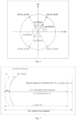
- the thin phase plate model describes the relationship between the wavefront error and the amount of cornea tissue removal that corrects the wavefront error, as schematically illustrated in Fig. 2 . Note that the various curves in Fig. 2 are exaggerated for convenience of illustration.
- the XY plane is a plane transverse to a depth direction Z of the eye.
- Fig. 2 also illustrates the cornea surface S(x,y) prior to treatment, and the desired cornea surface S0 after treatment.
- the wavefront W(x,y) is a distorted wavefront generated by the distorted shape of the cornea surface S, while the desired cornea surface S0 will generate the desired planar wavefront W1.
- the difference ⁇ (x,y) between the distorted cornea surface S(x,y) and the desired cornea surface S0 is the excessive cornea thickness to be removed by the lenticule extraction procedure.
- the desired cornea surface S0 is placed at the minimum point (x0,y0) of the distorted cornea surface, which gives the minimum amount of excessive cornea thickness ⁇ (x,y).
- the initial wavefront W0 is defined at the same location, and the desired planar wavefront W1 is defined at the corresponding maximum point of the distorted wavefront W(x,y).
- the distance between the desired planar wavefront W1 and the initial wavefront W0 at this location (x0,y0) is denoted W max .
- the distance d air (x,y) between the cornea surface S(x,y) and the wavefront W(x,y) is the distance traveled by the wave in the air at that location.
- the thin phase plate model assumes that all rays propagate in parallel and are normal to the cornea tissue and the wavefront sensor. However, because the cornea surface of a free eye is convex and the lenticule is a positive meniscus shape, the actual optical paths of light rays do not satisfy these assumptions. The thin phase plate approximation leads to about 10% under correction. Accordingly, embodiments of the present invention provide a modified thin phase plate model for calculating the lenticule shape. The modification is based on a comparison between the Munnerlyn model and the thin phase plate model for spherical aberration.
- the Munnerlyn model (or Munnerlyn formula) is a conventional technology used to calculate corneal lenticule shapes based on the amount of desired correction of the manifest refractive power.
- the Munnerlyn model is applied to a cornea in a free eye, so the lenticule has the shape of a positive meniscus lens. (Note that the descriptions here use correction for myopic error as an example.)
- Fig. 3 schematically illustrates the relation between lenticule thickness for a symmetrical biconvex lenticule used in the thin phase plate model and a meniscus lenticule used in the Munnerlyn model.
- the biconvex lenticule in the thin phase plate model is formed by two lenticule surfaces having radius of curvature (RoC) R and -R, respectively.
- the center thickness of the lenticule is denoted ⁇ 01 .
- the meniscus lenticule in the Munnerlyn model is formed by two lenticule surfaces having radius of curvature R 1 and R 2 , respectively.
- the center thickness of the lenticule is denoted ⁇ 02 .
- the optical zone i.e., the part of the lenticule that effectuates optical correction
- has a diameter OZ and radius L OZ/2.
- ⁇ 02 P R c 2 2 n c ⁇ 1 ⁇ ⁇
- H H R 1 L ⁇ H R 2 L 1 ⁇ n C ⁇ 1 n C ⁇ H ′
- R 2 L H ′ R c L ⁇ 2 ⁇ ⁇ ⁇ 02 1 ⁇ n C ⁇ 1 n C ⁇ H ′ R c L
- H is the sagitta function, i.e., the cord height of a circular arc
- H R L R ⁇ R 2 ⁇ L 2 , where R is R1, R2, or Rc
- H' is the partial derivative of H with respect to R
- the factor ⁇ 02 / ⁇ 01 is multiplied to the thickness function calculated by the thin phase plate model (Eq. (1)) to give the corrected thickness function ⁇ (r, ⁇ ) (Eq. (4)):
- ⁇ r ⁇ 2 R K 2 n c ⁇ 1 n c ⁇ L 2 + R K 2 ⁇ L 2 ⁇ R K + R K 2 ⁇ L 2 ⁇ W max ⁇ W r ⁇ n c ⁇ 1 ⁇ ⁇ MT ⁇ W max ⁇ W r ⁇ n c ⁇ 1
- the lenticule thickness function given by the modified thin phase plate model will agree with the lenticule thickness function given by the Munnerlyn formula for spherical optical power.
- the correction factor also corrects other aberration components contained in the thickness function calculated from measured wavefront by the thin phase plate model.
- the modified thin phase plate model gives a corrected result consistent with the conventional Munnerlyn formula for spherical aberration, while providing corresponding corrections for other aberrations in the measured wavefront.
- Fig. 4 shows a table that summarizes calculated values of the Munnerlyn correction factor applied to the thin phase plate model, as well as the values of lenticule center thickness according to the thin phase plate model and the Munnerlyn model, for a variety of K values and optical zone diameters.
- the wavefront map contains a spherical power as well as other aberration components.
- the wavefront map may be represented as a sum of a plurality of Zernike polynomials (a sequence of orthogonal polynomials on a two-dimensional unit disk) with corresponding Zernike coefficients.
- Zernike coefficients The relationship between Zernike coefficients and the manifest spherical and cylindrical refraction errors are as follows (Eq.
- a 3 ⁇ a 2,-2 , a 4 ⁇ a 2,0 and a 5 ⁇ a 2,2 are third, fourth and fifth Zernike coefficients
- SPH and CYL are the spherical and cylindrical refractive powers at the cornea plane; and ⁇ axis is the axis of the cylindrical refractive power.
- physician adjustment may be calculated as follows (see Fig. 6 ).
- the wavefront map as a sum of Zernike polynomials to obtain the original Zernike coefficients (step S61)
- the spherical and cylindrical powers at cornea plane for optical infinity, SPH wc , CYL wc are calculated from these original Zernike coefficients using Eqs. (6) and (7) (step S62).
- the powers are converted to equivalent values under manifest measurement conditions L and V, SPH wm , CYL wm , using Eq. (8) (step S63).
- step S66 Other adjustments may be added to the calculated optical powers (step S66), for example, a spherical refractive error introduced by a non-refractive "flat add", described below with reference to Fig. 7 .
- the non-refractive flat add is a layer of uniform thickness added to the lenticule thickness for purposes of improving the mechanical properties of the lenticule.
- the first surface (R 0 ) is the cornea anterior surface because only this surface, not the cutting surfaces of the lenticule, has the refractive power.
- R 0 R K is used.
- This correction is to be added to the spherical power at cornea plane for optical infinity.
- FIG. 8 schematically illustrates the relationship between a lenticule in a free cornea and an applanated cornea and definitions of parameters for applanation correction.
- a biconvex lenticule in the applanated cornea panel b
- a meniscus lenticule in the free cornea panel a
- An imaginary straight center line 81b in the applanated cornea which is parallel to the applanated cornea surface at a distance He and passes through the edge of the lenticule, corresponds to an arc 81a in the free cornea having a radius of curvature R ⁇ -H C , where R ⁇ is the radius of curvature of the free cornea at the meridian angle ⁇ .
- a given point 82b in the applanated cornea located on the center line 81b at a distance ⁇ (polar radius after applanation) from the Z axis corresponds to a point 82a in the free cornea located on the arc 81a at a distance r (polar radius before applanation) from the Z axis with a corresponding zenith angle ⁇ .
- the arc length of the point 82a along the arc 81a is equal to the distance ⁇ of the point 82b along the straight line 81b, both measured from the intersections with the Z axis.
- the thickness of the lenticule in the applanated cornea at the point 82b is denoted ⁇ L ( ⁇ , ⁇ )
- the thickness of the lenticule in the free cornea at the corresponding point 82a is denoted ⁇ (r, ⁇ ).
- the adjustments and corrections can now be applied to calculate adjusted Zernike coefficients for the adjusted wavefront (step S67), and then the lenticule cutting profile (step S68), in the applanated cornea.
- LOA lower-order aberrations
- HOA higher-order aberrations
- the lenticule thickness profile in the applanated cornea can now be calculated from the adjusted wavefront W( ⁇ , ⁇ m ) by applying the Munnerlyn correction factor, using Eq. (4).
- ⁇ TOP represents the top-to-total ratio of the amount of the lower-order part that is distributed to the top lenticule surface (the rest, 1- ⁇ TOP , is distributed to the bottom lenticule surface).
- the bottom lenticule surface contains both HOA part and LOA part
- the top lenticule surface contains both HOA part and LOA part
- One advantage of distributing the HOA to the bottom lenticule surface alone is that the bottom lenticule incision is typically formed first, where no or negligible gas bubbles have formed in the cornea from photodisruption by the laser beam. Gas bubbles tend to interfere with subsequent cutting, for example, the cutting of the top lenticule surface. Therefore, the shape of the formed bottom surface is generally more accurate than that of the top surface, and can better express the HOA part which typically has smaller magnitude and higher frequency.
- each of the bottom and top surfaces has a peripheral transition zone, the shape of which deviate from the above-calculated shapes for the bottom and top surfaces.
- the center areas of the bottom and top surfaces that have the above-calculated shapes are referred to as the optical zone.
- the transition zones are employed to improve the mechanical properties of the lenticule and for other beneficial reasons.
- the lenticule incisions may further include a ring cut that extends near the edge of the lenticule and intersects both the bottom and top surfaces and a pocket cut located outside of the optical zone. Any suitable shapes for the transition zone, ring cut, and pocket cut may be used.
- An entry cut is also formed to connect the lenticule to the anterior cornea surface for purposes of lenticule extraction.
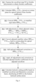
- the steps of the wavefront-guided corneal lenticule extraction calculation include the following ( Fig. 9 ):
- Fig. 10 shows an ophthalmic laser surgical system 10 for making an incision in a tissue 12 of a patient's eye.
- the system 10 includes, but is not limited to, a laser 14 capable of generating a pulsed laser beam, an energy control module 16 for varying the pulse energy of the pulsed laser beam, a fast scanline movement control module 20 for generating a fast scanline of the pulsed laser beam (described in more detail later), a controller 22, and a slow scanline movement control module 28 for moving the laser scanline and delivering it to the tissue 12.
- the controller 22 such as a processor operating suitable control software, is operatively coupled with the fast scanline movement control module 20, the slow scanline movement control module 28, and the energy control module 16 to direct the scanline of the pulsed laser beam along a scan pattern on or in the tissue 12.
- the system 10 further includes a beam splitter 26 and a imaging device 24 coupled to the controller 22 for a feedback control mechanism (not shown) of the pulsed laser beam.
- Other feedback methods may also be used.
- the pattern of pulses may be summarized in machine readable data of tangible storage media in the form of a treatment table.
- the treatment table may be adjusted according to feedback input into the controller 22 from an automated image analysis system in response to feedback data provided from a monitoring system feedback system (not shown).
- Laser 14 may comprise a femtosecond laser capable of providing pulsed laser beams, which may be used in optical procedures, such as localized photodisruption (e.g., laser induced optical breakdown). Localized photodisruptions can be placed at or below the surface of the tissue or other material to produce high-precision material processing.
- a micro-optics scanning system may be used to scan the pulsed laser beam to produce an incision in the material, create a flap of the material, create a pocket within the material, form removable structures of the material, and the like.
- the term “scan” or “scanning” refers to the movement of the focal point of the pulsed laser beam along a desired path or in a desired pattern.
- the laser 14 may comprise a laser source configured to deliver an ultraviolet laser beam comprising a plurality of ultraviolet laser pulses capable of photodecomposing one or more intraocular targets within the eye.
- the laser system 10 may be used to photoalter a variety of materials (e.g., organic, inorganic, or a combination thereof), the laser system 10 is suitable for ophthalmic applications in some embodiments.
- the focusing optics direct the pulsed laser beam toward an eye (for example, onto or into a cornea) for plasma mediated (for example, non-UV) photoablation of superficial tissue, or into the stroma of the cornea for intrastromal photodisruption of tissue.
- the surgical laser system 10 may also include a lens to change the shape (for example, flatten or curve) of the cornea prior to scanning the pulsed laser beam toward the eye.
- Fig. 11 shows another exemplary diagram of the laser system 10.
- Fig. 11 shows components of a laser delivery system including a moveable XY-scanner (or movable XY-stage) 28 of a miniaturized femtosecond laser system.
- the system 10 uses a femtosecond oscillator, or a fiber oscillator-based low energy laser. This allows the laser to be made much smaller.
- the laser-tissue interaction is in the low-density-plasma mode.
- An exemplary set of laser parameters for such lasers include pulse energy in the 40-100 nJ range and pulse repetitive rates (or "rep rates") in the 2-40 MHz range.
- a fast-Z scanner 25 and a resonant scanner 21 direct the laser beam to a scanline rotator 23.
- the system 10 also includes a patient interface design that has a fixed cone nose 31 and a contact lens 32 that engages with the patient's eye.
- a beam splitter may be placed inside the cone 31 of the patient interface to allow the whole eye to be imaged via visualization optics.
- the system 10 may use: optics with a 0.6 numerical aperture (NA) which would produce 1.1 ⁇ m Full Width at Half Maximum (FWHM) focus spot size; and a resonant scanner 21 that produces 0.2-1.2 mm scan line with the XY-scanner scanning the resonant scan line to a 1.0 mm field.
- the prism 23 e.g., a Dove or Pechan prism, or the like
- the fast-Z scanner 25 sets the incision depth.
- the slow scanline movement control module employs a movable XY-stage 28 carrying an objective lens with Z-scanning capability 27, referred to as slow-Z scanner because it is slower than the fast-Z scanner 25.
- the movable XY-stage 28 moves the objective lens to achieve scanning of the laser scanline in the X and Y directions.
- the objective lens changes the depth of the laser scanline in the tissue.
- the energy control and auto-Z module 16 may include appropriate components to control the laser pulse energy, including attenuators, etc. It may also include an auto-Z module which employs a confocal or non-confocal imaging system to provide a depth reference.
- the miniaturized femtosecond laser system 10 may be a desktop system so that the patient sits upright while being under treatment.
- the miniaturized laser system may be designed as a conventional femtosecond laser system, where the patient is treated while lying down.
- Fig. 12 illustrates a simplified block diagram of an exemplary controller 22 that may be used by the laser system 10 according to an embodiment of this invention to control the laser system 10 and execute at least some of the steps discussed in detail below.
- Controller 22 typically includes at least one processor 52 which may communicate with a number of peripheral devices via a bus subsystem 54.
- peripheral devices may include a storage subsystem 56, comprising a memory subsystem 58 (e.g., random access memory (RAM) 70, read only memory (ROM) 72, etc.) and a file storage subsystem 60 (e.g., hard disk drive, optical disc drive, solid-state memory, etc.), user interface input devices 62 (e.g., keyboard, mouse, trackball, touch pad, scanner, foot pedals, a joystick, microphones, etc.), user interface output devices 64 (e.g., display screen, printer, audio output, etc.), and a network interface subsystem 66 (wired or wireless).
- Network interface subsystem 66 provides an interface to outside networks 68 and/or other devices.
- Storage subsystem 56 can store the basic programming and data constructs that provide the functionality of the various embodiments of the present invention. For example, a database and modules implementing the functionality of the methods according to embodiments of the present invention, as described herein, may be stored in storage subsystem 56. These software modules are generally executed by processor 52.
- controller 22 depicted in Fig. 12 is intended only as an example for purposes of illustrating only one embodiment of the present invention. Many other configurations of controller 22, having more or fewer components than those depicted in Fig. 12 , are possible.
- laser system 10 additional components and subsystems may be included with laser system 10.
- spatial and/or temporal integrators may be included to control the distribution of energy within the laser beam.
- Ablation effluent evacuators/filters, aspirators, and other ancillary components of the surgical laser system are known in the art, and may be included in the system.
- an imaging device or system may be used to guide the laser beam.
Landscapes
- Health & Medical Sciences (AREA)
- Ophthalmology & Optometry (AREA)
- Life Sciences & Earth Sciences (AREA)
- Animal Behavior & Ethology (AREA)
- Engineering & Computer Science (AREA)
- Biomedical Technology (AREA)
- Heart & Thoracic Surgery (AREA)
- Vascular Medicine (AREA)
- Nuclear Medicine, Radiotherapy & Molecular Imaging (AREA)
- Surgery (AREA)
- General Health & Medical Sciences (AREA)
- Public Health (AREA)
- Veterinary Medicine (AREA)
- Physics & Mathematics (AREA)
- Optics & Photonics (AREA)
- Eye Examination Apparatus (AREA)
- Radiation-Therapy Devices (AREA)
- Laser Surgery Devices (AREA)
Applications Claiming Priority (3)
| Application Number | Priority Date | Filing Date | Title |
|---|---|---|---|
| US17/653,127 US12290474B2 (en) | 2022-03-01 | 2022-03-01 | Ophthalmic laser surgical system and method for wavefront-guided corneal lenticule extraction for vision correction |
| EP23711153.9A EP4486269A1 (fr) | 2022-03-01 | 2023-02-28 | Système chirurgical laser ophtalmique et méthode d'extraction de lenticule cornéen guidée par front d'onde pour correction de vision |
| PCT/IB2023/051852 WO2023166412A1 (fr) | 2022-03-01 | 2023-02-28 | Système chirurgical laser ophtalmique et méthode d'extraction de lenticule cornéen guidée par front d'onde pour correction de vision |
Related Parent Applications (2)
| Application Number | Title | Priority Date | Filing Date |
|---|---|---|---|
| EP23711153.9A Division EP4486269A1 (fr) | 2022-03-01 | 2023-02-28 | Système chirurgical laser ophtalmique et méthode d'extraction de lenticule cornéen guidée par front d'onde pour correction de vision |
| EP23711153.9A Division-Into EP4486269A1 (fr) | 2022-03-01 | 2023-02-28 | Système chirurgical laser ophtalmique et méthode d'extraction de lenticule cornéen guidée par front d'onde pour correction de vision |
Publications (2)
| Publication Number | Publication Date |
|---|---|
| EP4491164A2 true EP4491164A2 (fr) | 2025-01-15 |
| EP4491164A3 EP4491164A3 (fr) | 2025-02-26 |
Family
ID=85640820
Family Applications (2)
| Application Number | Title | Priority Date | Filing Date |
|---|---|---|---|
| EP24207471.4A Pending EP4491164A3 (fr) | 2022-03-01 | 2023-02-28 | Système et procédé chirurgicaux laser ophtalmique pour l'extraction de lenticule cornéen guidée par front d'onde pour la correction de la vision |
| EP23711153.9A Pending EP4486269A1 (fr) | 2022-03-01 | 2023-02-28 | Système chirurgical laser ophtalmique et méthode d'extraction de lenticule cornéen guidée par front d'onde pour correction de vision |
Family Applications After (1)
| Application Number | Title | Priority Date | Filing Date |
|---|---|---|---|
| EP23711153.9A Pending EP4486269A1 (fr) | 2022-03-01 | 2023-02-28 | Système chirurgical laser ophtalmique et méthode d'extraction de lenticule cornéen guidée par front d'onde pour correction de vision |
Country Status (4)
| Country | Link |
|---|---|
| US (2) | US12290474B2 (fr) |
| EP (2) | EP4491164A3 (fr) |
| CN (1) | CN118829412A (fr) |
| WO (1) | WO2023166412A1 (fr) |
Citations (2)
| Publication number | Priority date | Publication date | Assignee | Title |
|---|---|---|---|---|
| US20160089270A1 (en) | 2014-09-25 | 2016-03-31 | Amo Development, Llc | Systems and methods for lenticular laser incision |
| US20200046558A1 (en) | 2018-08-07 | 2020-02-13 | Amo Development, Llc | High speed corneal lenticular incision using a femtosecond laser |
Family Cites Families (5)
| Publication number | Priority date | Publication date | Assignee | Title |
|---|---|---|---|---|
| US8444632B2 (en) | 2008-11-05 | 2013-05-21 | Carl Zeiss Meditec Ag | Method of performing refractive laser eye surgery centered along the visual axis of a human eye |
| US9504376B2 (en) | 2009-12-22 | 2016-11-29 | Amo Wavefront Sciences, Llc | Optical diagnosis using measurement sequence |
| WO2017025115A1 (fr) | 2015-08-07 | 2017-02-16 | Wavelight Gmbh | Repères de la cornée en chirurgie de correction de la vision |
| CA3030002A1 (fr) * | 2016-07-07 | 2018-01-11 | Amo Development, Llc | Incision laser lenticulaire utilisant des cartes guidees de front d'onde |
| EP4157172A1 (fr) * | 2020-05-27 | 2023-04-05 | Alcon Inc. | Procédé de correction d'aberrations d'ordre supérieur à l'aide d'une correction de vision laser |
-
2022
- 2022-03-01 US US17/653,127 patent/US12290474B2/en active Active
-
2023
- 2023-02-28 EP EP24207471.4A patent/EP4491164A3/fr active Pending
- 2023-02-28 EP EP23711153.9A patent/EP4486269A1/fr active Pending
- 2023-02-28 WO PCT/IB2023/051852 patent/WO2023166412A1/fr not_active Ceased
- 2023-02-28 CN CN202380024690.1A patent/CN118829412A/zh active Pending
-
2025
- 2025-04-30 US US19/195,561 patent/US20250255752A1/en active Pending
Patent Citations (2)
| Publication number | Priority date | Publication date | Assignee | Title |
|---|---|---|---|---|
| US20160089270A1 (en) | 2014-09-25 | 2016-03-31 | Amo Development, Llc | Systems and methods for lenticular laser incision |
| US20200046558A1 (en) | 2018-08-07 | 2020-02-13 | Amo Development, Llc | High speed corneal lenticular incision using a femtosecond laser |
Also Published As
| Publication number | Publication date |
|---|---|
| EP4491164A3 (fr) | 2025-02-26 |
| WO2023166412A1 (fr) | 2023-09-07 |
| US20250255752A1 (en) | 2025-08-14 |
| US12290474B2 (en) | 2025-05-06 |
| US20230277377A1 (en) | 2023-09-07 |
| EP4486269A1 (fr) | 2025-01-08 |
| CN118829412A (zh) | 2024-10-22 |
Similar Documents
| Publication | Publication Date | Title |
|---|---|---|
| US11717443B2 (en) | Systems and methods for femtosecond laser photorefractive keratectomy | |
| US10369052B2 (en) | Systems and methods for lenticular laser incision | |
| EP3481346B1 (fr) | Incision laser lenticulaire utilisant des cartes guidées de front d'onde | |
| US11944575B2 (en) | Lenticular laser incision for low myopia and/or hyperopiapatients | |
| US11564838B2 (en) | Systems and methods for lenticular laser incision | |
| US12150900B2 (en) | Corneal lenticular incision using a femtosecond laser with optimized pulse energy and scan line steps | |
| US11253398B2 (en) | Methods for lenticular laser incision | |
| AU2019323793A1 (en) | Systems and methods for lenticular laser incision | |
| EP4491164A2 (fr) | Système et procédé chirurgicaux laser ophtalmique pour l'extraction de lenticule cornéen guidée par front d'onde pour la correction de la vision | |
| US20260115046A1 (en) | Corneal lenticular formation using a femtosecond laser for hyperopia and mixed astigmatism correction |
Legal Events
| Date | Code | Title | Description |
|---|---|---|---|
| PUAI | Public reference made under article 153(3) epc to a published international application that has entered the european phase |
Free format text: ORIGINAL CODE: 0009012 |
|
| STAA | Information on the status of an ep patent application or granted ep patent |
Free format text: STATUS: REQUEST FOR EXAMINATION WAS MADE |
|
| 17P | Request for examination filed |
Effective date: 20241018 |
|
| AC | Divisional application: reference to earlier application |
Ref document number: 4486269 Country of ref document: EP Kind code of ref document: P |
|
| AK | Designated contracting states |
Kind code of ref document: A2 Designated state(s): AL AT BE BG CH CY CZ DE DK EE ES FI FR GB GR HR HU IE IS IT LI LT LU LV MC ME MK MT NL NO PL PT RO RS SE SI SK SM TR |
|
| PUAL | Search report despatched |
Free format text: ORIGINAL CODE: 0009013 |
|
| AK | Designated contracting states |
Kind code of ref document: A3 Designated state(s): AL AT BE BG CH CY CZ DE DK EE ES FI FR GB GR HR HU IE IS IT LI LT LU LV MC ME MK MT NL NO PL PT RO RS SE SI SK SM TR |
|
| RIC1 | Information provided on ipc code assigned before grant |
Ipc: A61F 9/008 20060101AFI20250120BHEP |