EP4491205A1 - Système de chauffage et d'alimentation d'un fluide à pulvériser dans une cavité intracorporelle - Google Patents
Système de chauffage et d'alimentation d'un fluide à pulvériser dans une cavité intracorporelle Download PDFInfo
- Publication number
- EP4491205A1 EP4491205A1 EP24187008.8A EP24187008A EP4491205A1 EP 4491205 A1 EP4491205 A1 EP 4491205A1 EP 24187008 A EP24187008 A EP 24187008A EP 4491205 A1 EP4491205 A1 EP 4491205A1
- Authority
- EP
- European Patent Office
- Prior art keywords
- bag
- fluid
- way
- heating
- partition walls
- Prior art date
- Legal status (The legal status is an assumption and is not a legal conclusion. Google has not performed a legal analysis and makes no representation as to the accuracy of the status listed.)
- Granted
Links
Images



Classifications
-
- A—HUMAN NECESSITIES
- A61—MEDICAL OR VETERINARY SCIENCE; HYGIENE
- A61M—DEVICES FOR INTRODUCING MEDIA INTO, OR ONTO, THE BODY; DEVICES FOR TRANSDUCING BODY MEDIA OR FOR TAKING MEDIA FROM THE BODY; DEVICES FOR PRODUCING OR ENDING SLEEP OR STUPOR
- A61M3/00—Medical syringes, e.g. enemata; Irrigators
- A61M3/02—Enemata; Irrigators
- A61M3/0233—Enemata; Irrigators characterised by liquid supply means, e.g. from pressurised reservoirs
- A61M3/0254—Enemata; Irrigators characterised by liquid supply means, e.g. from pressurised reservoirs the liquid being pumped
- A61M3/0258—Enemata; Irrigators characterised by liquid supply means, e.g. from pressurised reservoirs the liquid being pumped by means of electric pumps
-
- A—HUMAN NECESSITIES
- A61—MEDICAL OR VETERINARY SCIENCE; HYGIENE
- A61M—DEVICES FOR INTRODUCING MEDIA INTO, OR ONTO, THE BODY; DEVICES FOR TRANSDUCING BODY MEDIA OR FOR TAKING MEDIA FROM THE BODY; DEVICES FOR PRODUCING OR ENDING SLEEP OR STUPOR
- A61M3/00—Medical syringes, e.g. enemata; Irrigators
- A61M3/02—Enemata; Irrigators
- A61M3/0204—Physical characteristics of the irrigation fluid, e.g. conductivity or turbidity
- A61M3/0216—Pressure
-
- A—HUMAN NECESSITIES
- A61—MEDICAL OR VETERINARY SCIENCE; HYGIENE
- A61M—DEVICES FOR INTRODUCING MEDIA INTO, OR ONTO, THE BODY; DEVICES FOR TRANSDUCING BODY MEDIA OR FOR TAKING MEDIA FROM THE BODY; DEVICES FOR PRODUCING OR ENDING SLEEP OR STUPOR
- A61M3/00—Medical syringes, e.g. enemata; Irrigators
- A61M3/02—Enemata; Irrigators
- A61M3/0233—Enemata; Irrigators characterised by liquid supply means, e.g. from pressurised reservoirs
- A61M3/0245—Containers therefor, e.g. with heating means or with storage means for cannula
-
- A—HUMAN NECESSITIES
- A61—MEDICAL OR VETERINARY SCIENCE; HYGIENE
- A61M—DEVICES FOR INTRODUCING MEDIA INTO, OR ONTO, THE BODY; DEVICES FOR TRANSDUCING BODY MEDIA OR FOR TAKING MEDIA FROM THE BODY; DEVICES FOR PRODUCING OR ENDING SLEEP OR STUPOR
- A61M2205/00—General characteristics of the apparatus
- A61M2205/33—Controlling, regulating or measuring
- A61M2205/3331—Pressure; Flow
- A61M2205/3341—Pressure; Flow stabilising pressure or flow to avoid excessive variation
-
- A—HUMAN NECESSITIES
- A61—MEDICAL OR VETERINARY SCIENCE; HYGIENE
- A61M—DEVICES FOR INTRODUCING MEDIA INTO, OR ONTO, THE BODY; DEVICES FOR TRANSDUCING BODY MEDIA OR FOR TAKING MEDIA FROM THE BODY; DEVICES FOR PRODUCING OR ENDING SLEEP OR STUPOR
- A61M2205/00—General characteristics of the apparatus
- A61M2205/33—Controlling, regulating or measuring
- A61M2205/3331—Pressure; Flow
- A61M2205/3344—Measuring or controlling pressure at the body treatment site
-
- A—HUMAN NECESSITIES
- A61—MEDICAL OR VETERINARY SCIENCE; HYGIENE
- A61M—DEVICES FOR INTRODUCING MEDIA INTO, OR ONTO, THE BODY; DEVICES FOR TRANSDUCING BODY MEDIA OR FOR TAKING MEDIA FROM THE BODY; DEVICES FOR PRODUCING OR ENDING SLEEP OR STUPOR
- A61M2205/00—General characteristics of the apparatus
- A61M2205/33—Controlling, regulating or measuring
- A61M2205/3368—Temperature
-
- A—HUMAN NECESSITIES
- A61—MEDICAL OR VETERINARY SCIENCE; HYGIENE
- A61M—DEVICES FOR INTRODUCING MEDIA INTO, OR ONTO, THE BODY; DEVICES FOR TRANSDUCING BODY MEDIA OR FOR TAKING MEDIA FROM THE BODY; DEVICES FOR PRODUCING OR ENDING SLEEP OR STUPOR
- A61M2205/00—General characteristics of the apparatus
- A61M2205/36—General characteristics of the apparatus related to heating or cooling
- A61M2205/3653—General characteristics of the apparatus related to heating or cooling by Joule effect, i.e. electric resistance
-
- A—HUMAN NECESSITIES
- A61—MEDICAL OR VETERINARY SCIENCE; HYGIENE
- A61M—DEVICES FOR INTRODUCING MEDIA INTO, OR ONTO, THE BODY; DEVICES FOR TRANSDUCING BODY MEDIA OR FOR TAKING MEDIA FROM THE BODY; DEVICES FOR PRODUCING OR ENDING SLEEP OR STUPOR
- A61M2206/00—Characteristics of a physical parameter; associated device therefor
- A61M2206/10—Flow characteristics
- A61M2206/22—Flow characteristics eliminating pulsatile flows, e.g. by the provision of a dampening chamber
Definitions
- endoscopic instruments In the clinical sector, the use of endoscopic instruments is made which are introduced into the human body through the natural orifices or special openings in order to reach the intracorporeal area on which a diagnosis is to be carried out or a treatment or a surgical operation is to be performed.
- Special channels are present internally of endoscopes for the passage of instruments suitable for carrying out surgical or diagnostic operations, of viewing instruments, as well as for the passage of a saline fluid utilised for spraying the cavity or site on which the diagnostic, therapeutic or surgical operations are to be carried out.
- the present invention concerns a system for heating and supplying a fluid to be sprayed into an intracorporeal cavity which, once heated, is to be supplied via a channel or conduit of the endoscopic instrument which is used in clinical-surgical procedures, such as, for example laparoscopy, laparotomy, hysteroscopy, endoscopy, arthroscopy, endourology.
- the cavity or area reached by the endoscopic instrument must be appropriately sprayed with a saline fluid with the purpose of washing, in order to keep the visual field of the operator clear, for example by removing corporeal fluids that may be present, or for dilating the tissues thus to enable the carrying out of the surgical procedure required, as well as preventing the patient's body temperature from excessively dropping, leading to hypothermia.
- a first factor that needs taking into consideration is constituted by the pressure with which the fluid is sprayed and reaches the cavity or area of interest.
- a second important factor relates to the temperature of the fluid to be sprayed, in fact an excessively low temperature not only creates problems of hypothermia but can have a negative impact on other haemodynamic parameters of the patient.
- TURP transurethral resection of the prostate
- the operation is made possible by a continuous washing of the cavities with solutions of mannitol or saline, with the inlet of washing liquid and exit thereof through the actual resectoscope.
- a spraying solution is utilised during the operation so as to distend the bladder.
- the spraying of the cavities subject to operation by fluids not appropriately controlled in terms of the spraying pressure thereof can create hyperdistensions of the cavities, and if they have an excessively low temperature with respect to the body temperature they can cause hypothermia with post-operative risks.
- a first known system used for heating a fluid which is to be sprayed into an intracorporeal cavity by means of an endoscopic instrument comprises use of a stator, positioned at a certain height with respect to the operating site, on which a consumable bag made of a plastic material is positioned and hooked, for example made of PVC, defining internally thereof a containing chamber of a saline fluid and having an outlet conduit of the fluid.
- the stator powered by an electrical current, heats the bag and thus the fluid contained internally thereof.
- the bag via the outlet conduit, is set in communication with a supply channel that is connected to the endoscopic instrument.
- the supply of the heated fluid to the endoscopic instrument takes place by force of gravity.
- the height at which the stator is positioned with respect to the operating site will then determine the supply pressure value of the fluid.
- the delay time i.e. the waiting time for heating the fluid, before the fluid can be sprayed, is quite long, and this circumstance can lengthen the operating times.
- the heating of the fluid internal of the bag is not uniform, and therefore the fluid can reach the cavity at an inappropriate temperature, and thus not completely heated to the appropriate temperature, causing the issues as previously evidenced, or at an excessive temperature, a circumstance that can lead to the risk of scalding in the patient.
- a heating oven for example by means of infrared rays or electrical resistances, internally of which a consumable bag made of a plastic material is positioned, for example made of PVC, defining internally thereof a containing chamber of a saline fluid and having an outlet conduit of the fluid, which is connected to a supply channel communicating with the endoscopic instrument.
- An overpressure is created in the oven, by injection of pressurised air, so as to compress the bag in such a way as to supply the heated fluid to the endoscopic instrument for subsequent spraying into the intracorporeal cavity subjected to the treatment or to the surgical operation.
- the aim of the present invention is therefore to provide a novel system for heating and supplying a fluid to be sprayed into an intracorporeal cavity able to obviate the drawbacks present in the prior art and mentioned in the foregoing.
- the system of the invention in its main and essential components, comprises: a bag (1) made of a plastic material that is deformable following application of heat for enabling an expansion of the bag, a pair of heating plates (2, 3) and a peristaltic pump (4), which are configured and arranged in the following way.
- the bag made of a deformable plastic material, for example PVC comprises a first inlet conduit (11) for inlet into the bag (1) of a fluid to be sprayed into an intracorporeal cavity, and a second outlet conduit (12) for outlet of the fluid from the bag (1)
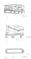
- the bag (1) (see for example figure 1 and figure 2 , or figure 9 ) is conformed in such a way as to comprise internally thereof a first series of partition walls (15) which originate from a first lateral edge (P1) of the bag (1) and a second series of partition walls (16) which originate from a second lateral edge (P2) of the bag (1), wherein the first series of partition walls (15) is intercalated with the second series of partition walls (16) in such a way as to identify, internally of the bag (1), a fluid conveying path in the form of a serpentine (10) which extends from the first inlet conduit (11) to the second outlet conduit (12).
- the first inlet conduit (11) of the bag (1) is configured to be connected to a supply source of fluid to be sprayed into an intracorporeal cavity in such a way that the fluid can enter the bag (1) and flow along the fluid conveying path in the form of a serpentine (10) up to the second outlet conduit (12).
- the first inlet conduit (11) can comprise a bifurcation in such a way as to be connectable to two distinct fluid supply pipes communicating with two distinct fluid supply sources to be sprayed into an intracorporeal cavity (see for example figure 9 ).
- the system of the invention can guarantee continuity of fluid supply to inside the bag, as, when a first supply source of fluid is exhausted, the bag can receive the fluid from a second supply source of fluid.
- the second outlet conduit (12) is configured to be connected to an endoscopic instrument suitable for being able to carry out the diagnostic or surgical operations required, so that the fluid in outlet from the second outlet conduit is sent into a channel present internally of the endoscopic instrument in order to be sprayed into the intracorporeal cavity, or site in which the endoscopic instrument is to carry out diagnostic and/or surgical operations.
- the pair of heating plates (2, 3) are configured and arranged in such a way as to be able to receive between them the bag (1) and, when activated, to heat the bag (1) and the contents thereof.
- the heating plates can be of the electrical resistance type, as provided with electric resistors or serpentines.
- the peristaltic pump (4) is arranged in such a way as to establish a fluid pumping flow coming from the supply source in such a way that the fluid flows along the fluid conveying path in the form of a serpentine (10) acquiring heat from the pair of heating plates (2, 3) so that the heated fluid is pumped through the second outlet conduit (12) to the endoscopic instrument in order to be sprayed into an intracorporeal cavity.
- the pair of heating plates (2, 3) are configured and activatable so as to heat the bag (1) to a temperature which can be comprised in a temperature range of 45°-60°C.
- the peristaltic pump (4) can be activatable to offer a pumping pressure which can vary within a range from 50 to 500 mbar.
- the pumping pressure of the fluid is regularised during its flow along the fluid conveying path in the form of a serpentine (10) in the bag (1), as the bag (1) deforms and expands, due to the heat received from the pair of heating plates (2, 3), thus behaving as a sort of "damper", i.e. an absorber of any eventual fluctuations present in the flow.
- the fluid arriving from the supply source of the fluid once it has entered the bag through the first inlet conduit, and while crossing the fluid conveying path in the form of a serpentine (10), is uniformly heated by the heat supplied by the pair of heating plates, and then can exit from the bag, through the second outlet conduit (12), at a suitable temperature for being sprayed into an intracorporeal cavity via a suitable endoscopic instrument connected to the second outlet conduit (12) of the bag (1).
- the partition walls of the first series of partition walls (15) present internally of the bag (1) are arranged with respect to the first lateral edge (P1) of the bag (1) in such a way as to form, with respect to the first lateral edge (P1), an angle ( ⁇ ) comprised between 90° and 150° (see the broken line in figure 1 ) and wherein the partition walls of the second series of partition walls (16) present internally of the bag (1) are arranged, with respect to the second lateral edge (P2) of the bag (1), in such a way as to form an angle comprised between 90° and 150° with respect to the second lateral wall.
- the ratio between the distance (H) (indicated in figure 1 ) between the first lateral edge (P1) and the second lateral edge (P2) of the bag (1), and the distance (D) (indicated in figure 1 ) beween two adjacent partition walls of the first (15) and second (16) series of partition walls is comprised in the range of 3.5 - 10.
- the peristaltic pump (4) comprises a rotor (40) peripherally having a series of lobes (41), with the peristaltic pump (4) arranged so that the lobes (41), when the rotor (40) is activated in rotation, act at the inlet conduit (11) or the outlet conduit (12) of the bag (1) so as to establish a pumping flow of the fluid coming from the supply source in such a way that the fluid flows along the fluid conveying path in the form of a serpentine (10), acquiring heat from the pair of heating plates (2, 3) so that the heated fluid is pumped through the second outlet conduit (12) to the endoscopic instrument in order to be sprayed into an intracorporeal cavity.
- the peristaltic pump (4) is arranged in such a way that the lobes (41), when the rotor (40) is activated in rotation, act at the inlet conduit (11) of the bag (1), with the system comprising an expansion chamber (42) along the first inlet conduit (11), in a position interposed between the bag (1) and the portion of the inlet conduit (11) on which the lobes (41) of the rotor (40) act (see for example the circuit diagram reported in figure 2 ).
- the fluid pumped by the peristaltic pump (4) is first supplied into the expansion chamber (42), partially filling it, before being pumped into the bag (1) and crossing the fluid conveying path in the form of a serpentine (10), enabling a further reduction of the onset of any fluctuations of the fluid flow during the circulation thereof internally of the bag (1).
- figure 10 includes the graphs relating to the progress of the fluid flow in three distinct situations.
- Curve C1 indicates the progress of the fluid flow when it is pumped from a peristaltic pump through a normal conduit.
- Curve C2 indicates the progress of the fluid flow when it is pumped to cross the bag of the invention, with no heating.
- curve C2 has fewer fluctuations than curve C1 owing to the particular inner conformation of the bag (1) which includes the flow conveying path in the form of a serpentine (10).
- Curve C3 indicates the progress of the fluid flow when it is pumped to cross the bag of the invention, with no heating, with the presence of the expansion chamber upstream of the bag.
- curve C3 has fewer fluctuations than curve C2, owing to the presence of the expansion chamber upstream of the bag.
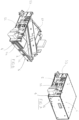
- the system of the invention can be made and configured in such a way that a first heating plate (2) of the pair of heating plates (2, 3) is arranged and mounted on a first structure (5) having a drawer or slide shape and wherein the second heating plate (3) of the pair of heating plates (2, 3) is arranged and mounted on a second structure (6) having a container shape.
- the second structure (6) having a container shape is conformed in such a way as to comprise internally thereof a housing, accessible from outside, having a shape such as to slidably receive the first structure (5) having a drawer or slide shape in such a way that the first structure (5) having a drawer or slide shape is placed in a position such that the first heating plate (2) is arranged facing the second heating plate (3) so as to close between them the bag (1) arranged and positioned on the first heating plate (2).
- the bag (1) preferably comprises respective slots (20) on the relative first and second lateral edges (P1, P2) with the first heating plate (2) comprising, peripherally on relative lateral edges, hook elements (22) conformed so as to be inserted in the slots (20) of the bag (1) in order to ensure the blocking of the bag (1) on the first heating plate (2).
- the first structure (5) having a drawer or slide shape comprises a base wall (51), on which the first heating plate (2) is mounted and arranged, and a front wall (52) arranged vertically at a first lateral edge of the base wall (51), wherein, when the first structure (5) having a drawer or slide shape is inserted in the housing of the second structure (6) having a container shape, the front wall (52) remains directly accessible from outside.
- the front wall (52) of the first structure (5) comprises a first aperture (53), having a shape suitable for allowing passage of the first inlet conduit (11) of the bag (1) in such a way that the first inlet conduit can be connected to the supply source of the fluid, and a second aperture (54), having a shape suitable for allowing passage of the second outlet conduit (12) of the bag (1) in such a way that the second outlet conduit can be connected to an endoscopic instrument.
- the rotor (40) of the peristaltic pump (4) is mounted on the front wall (52) in a position such as to remain positioned internally of the second structure (6) in the form of a container when the first structure (5) having a drawer or slide shape is inserted in the housing of the second structure (6) having the shape of a container.
- system of the invention can further comprise also at least an inclined separating wall (58), which is arranged in the first structure (5) having a drawer or slide shape, below the first heating plate (2), and which is configured to receive any leaks of fluid exiting from the bag (1) and to direct the leaks of fluid towards a collection tray (59) also arranged in the first structure (5) having a drawer or slide shape.
- inclined separating wall 58
- the system of the invention can further comprise also at least an inclined separating wall (58), which is arranged in the first structure (5) having a drawer or slide shape, below the first heating plate (2), and which is configured to receive any leaks of fluid exiting from the bag (1) and to direct the leaks of fluid towards a collection tray (59) also arranged in the first structure (5) having a drawer or slide shape.
- the system can advantageously also comprise a moisture detector, positioned in the first structure (5) in proximity or at the inclined separating wall (58) or at the collection tray (59), in such a way as to detect any leaks of fluid from the bag, and thus enable the extraction of the first structure (5) from the second structure (6) and the removal of the damaged bag.
- a moisture detector positioned in the first structure (5) in proximity or at the inclined separating wall (58) or at the collection tray (59), in such a way as to detect any leaks of fluid from the bag, and thus enable the extraction of the first structure (5) from the second structure (6) and the removal of the damaged bag.
- Another further preferred aspect of the system in the particular embodiment described in the foregoing, consists in the arrangement of the pair of heating plates which can be arranged diagonally in the first structure (5) and in the second structure (6), with an angle of inclination with respect to an axial axis comprised in a range between 30° and 70°.
- the pair of heating plates (2, 3) comprise temperature detectors (20, 30) arranged and configured to detect the heating temperature of the bag (1) (see for example figure 5 ), for example constituted by thermocouples.
- the temperature detectors (20, 30) are interfaced with a command and control unit (not illustrated, and arranged either on the first structure or on the second structure), arranged in such a way as to be able to intervene on the heating plates in order to increase or reduce the heating temperature thereof according to needs.
- the system can also comprise at least a pressure detector (not illustrated), arranged in such a way as to detect the pumping pressure of the flow of fluid which crosses the flow conveying path in the form of a serpentine (10) of the bag (1).
- a pressure detector not illustrated
- the pressure detector is also interfaced with the command and control unit in order to enable a regulating of the functioning of the peristaltic pump.
Landscapes
- Health & Medical Sciences (AREA)
- Engineering & Computer Science (AREA)
- Anesthesiology (AREA)
- Biomedical Technology (AREA)
- Heart & Thoracic Surgery (AREA)
- Hematology (AREA)
- Life Sciences & Earth Sciences (AREA)
- Animal Behavior & Ethology (AREA)
- General Health & Medical Sciences (AREA)
- Public Health (AREA)
- Veterinary Medicine (AREA)
- Thermotherapy And Cooling Therapy Devices (AREA)
- Infusion, Injection, And Reservoir Apparatuses (AREA)
Applications Claiming Priority (1)
| Application Number | Priority Date | Filing Date | Title |
|---|---|---|---|
| IT102023000014529A IT202300014529A1 (it) | 2023-07-12 | 2023-07-12 | Sistema per riscaldare ed alimentare un fluido da irrorare in una cavita’ intracorporea |
Publications (3)
| Publication Number | Publication Date |
|---|---|
| EP4491205A1 true EP4491205A1 (fr) | 2025-01-15 |
| EP4491205C0 EP4491205C0 (fr) | 2026-01-28 |
| EP4491205B1 EP4491205B1 (fr) | 2026-01-28 |
Family
ID=88207406
Family Applications (1)
| Application Number | Title | Priority Date | Filing Date |
|---|---|---|---|
| EP24187008.8A Active EP4491205B1 (fr) | 2023-07-12 | 2024-07-08 | Système de chauffage et d'alimentation d'un fluide à pulvériser dans une cavité intracorporelle |
Country Status (2)
| Country | Link |
|---|---|
| EP (1) | EP4491205B1 (fr) |
| IT (1) | IT202300014529A1 (fr) |
Citations (5)
| Publication number | Priority date | Publication date | Assignee | Title |
|---|---|---|---|---|
| EP0292076B1 (fr) * | 1987-05-22 | 1992-09-23 | Medistad Holland B.V. | Dispositif pour chauffer le sang |
| WO1992017040A1 (fr) * | 1991-03-15 | 1992-10-01 | In-Touch Products Co. | Coffret chauffant pour liquides parenteraux, systeme et methodes |
| US5199604A (en) * | 1990-05-04 | 1993-04-06 | Sultan Chemists, Inc. | Irrigation system and method for delivering a selected one of multiple liquid solutions to a treatment site |
| EP0800835A2 (fr) * | 1996-04-11 | 1997-10-15 | Wisap Gesellschaft Für Wissenschaftlichen Apparatebau Mbh | Appareil d'irrigation des cavités du corps humain |
| CN205126983U (zh) * | 2015-11-19 | 2016-04-06 | 南京医科大学第一附属医院 | 一种加压灌注可升温胸腔镜手术冲洗装置 |
-
2023
- 2023-07-12 IT IT102023000014529A patent/IT202300014529A1/it unknown
-
2024
- 2024-07-08 EP EP24187008.8A patent/EP4491205B1/fr active Active
Patent Citations (5)
| Publication number | Priority date | Publication date | Assignee | Title |
|---|---|---|---|---|
| EP0292076B1 (fr) * | 1987-05-22 | 1992-09-23 | Medistad Holland B.V. | Dispositif pour chauffer le sang |
| US5199604A (en) * | 1990-05-04 | 1993-04-06 | Sultan Chemists, Inc. | Irrigation system and method for delivering a selected one of multiple liquid solutions to a treatment site |
| WO1992017040A1 (fr) * | 1991-03-15 | 1992-10-01 | In-Touch Products Co. | Coffret chauffant pour liquides parenteraux, systeme et methodes |
| EP0800835A2 (fr) * | 1996-04-11 | 1997-10-15 | Wisap Gesellschaft Für Wissenschaftlichen Apparatebau Mbh | Appareil d'irrigation des cavités du corps humain |
| CN205126983U (zh) * | 2015-11-19 | 2016-04-06 | 南京医科大学第一附属医院 | 一种加压灌注可升温胸腔镜手术冲洗装置 |
Also Published As
| Publication number | Publication date |
|---|---|
| EP4491205C0 (fr) | 2026-01-28 |
| EP4491205B1 (fr) | 2026-01-28 |
| IT202300014529A1 (it) | 2025-01-12 |
Similar Documents
| Publication | Publication Date | Title |
|---|---|---|
| US5542928A (en) | Method and device for thermal ablation having improved heat transfer | |
| US20100004595A1 (en) | Balloon catheter systems for treating uterine disorders having fluid line de-gassing assemblies and methods therefor | |
| EP2338427B1 (fr) | Système d'ablation thermique avec un agent thérapeutique pouvant être administré | |
| CA2725750C (fr) | Systemes de catheter a ballonnet et procede de traitement des troubles uterins | |
| US9226789B2 (en) | Thermal ablation system | |
| US5653692A (en) | Method and system for direct heating of fluid solution in a hollow body organ | |
| CN101437477B (zh) | 具有带液体返回通道的多腔管的热交换导管 | |
| US5437673A (en) | Closed circulation tissue warming apparatus and method of using the same in prostate surgery | |
| ES2677574T3 (es) | Sistemas médicos | |
| JP2010540028A (ja) | 手持ち式熱焼灼装置 | |
| US8323324B2 (en) | Therapeutic heating and cooling via temperature management of a colon-inserted dual balloon | |
| JP7840333B2 (ja) | 肺腫瘍を治療するためのシステム及び装置 | |
| US20130184791A1 (en) | Apparatus for performing heat treatment | |
| EP4491205B1 (fr) | Système de chauffage et d'alimentation d'un fluide à pulvériser dans une cavité intracorporelle | |
| EP2528636B1 (fr) | Dispositif et procédé de traitement de la bursite | |
| JPH05504078A (ja) | 再灌流装置 |
Legal Events
| Date | Code | Title | Description |
|---|---|---|---|
| PUAI | Public reference made under article 153(3) epc to a published international application that has entered the european phase |
Free format text: ORIGINAL CODE: 0009012 |
|
| STAA | Information on the status of an ep patent application or granted ep patent |
Free format text: STATUS: THE APPLICATION HAS BEEN PUBLISHED |
|
| AK | Designated contracting states |
Kind code of ref document: A1 Designated state(s): AL AT BE BG CH CY CZ DE DK EE ES FI FR GB GR HR HU IE IS IT LI LT LU LV MC ME MK MT NL NO PL PT RO RS SE SI SK SM TR |
|
| STAA | Information on the status of an ep patent application or granted ep patent |
Free format text: STATUS: REQUEST FOR EXAMINATION WAS MADE |
|
| 17P | Request for examination filed |
Effective date: 20250710 |
|
| GRAP | Despatch of communication of intention to grant a patent |
Free format text: ORIGINAL CODE: EPIDOSNIGR1 |
|
| STAA | Information on the status of an ep patent application or granted ep patent |
Free format text: STATUS: GRANT OF PATENT IS INTENDED |
|
| INTG | Intention to grant announced |
Effective date: 20250826 |
|
| GRAS | Grant fee paid |
Free format text: ORIGINAL CODE: EPIDOSNIGR3 |
|
| GRAA | (expected) grant |
Free format text: ORIGINAL CODE: 0009210 |
|
| STAA | Information on the status of an ep patent application or granted ep patent |
Free format text: STATUS: THE PATENT HAS BEEN GRANTED |
|
| AK | Designated contracting states |
Kind code of ref document: B1 Designated state(s): AL AT BE BG CH CY CZ DE DK EE ES FI FR GB GR HR HU IE IS IT LI LT LU LV MC ME MK MT NL NO PL PT RO RS SE SI SK SM TR |
|
| REG | Reference to a national code |
Ref country code: CH Ref legal event code: F10 Free format text: ST27 STATUS EVENT CODE: U-0-0-F10-F00 (AS PROVIDED BY THE NATIONAL OFFICE) Effective date: 20260128 Ref country code: GB Ref legal event code: FG4D |
|
| REG | Reference to a national code |
Ref country code: DE Ref legal event code: R096 Ref document number: 602024002278 Country of ref document: DE |
|
| REG | Reference to a national code |
Ref country code: IE Ref legal event code: FG4D |
|
| U01 | Request for unitary effect filed |
Effective date: 20260224 |
|
| U07 | Unitary effect registered |
Designated state(s): AT BE BG DE DK EE FI FR IT LT LU LV MT NL PT RO SE SI Effective date: 20260302 |